


-
在光学系统中,光学元件作为其重要组成部分,其表面特性将对系统的各项性能产生重要影响[1-2]。例如,在光学系统的实际应用中,当镜面存在污染时,污染粒子不仅会造成镜面散射增加,还会改变其吸收特性,进而影响光学系统性能。一方面,大型光学系统大都曝露在复杂的外界环境中,随着时间的推移,空气中的颗粒污染物会沉积在光学元件表面,从而增大元件的表面发射率,严重影响红外光学系统的成像质量;另一方面,表面污染物的吸收特性不仅会降低激光传输的能量,同时将吸收的热量转化为热沉积,进而将造成光学元件的热损伤。
对于光学元件吸收特性的研究,国内大都是光学材料和光学薄膜热损伤的报道[3-6],但是对于光学元件表面吸收特性的研究却鲜有报道。国外学者C.F.Bohrena、D.R.Huffman等[7-9],则从理论上对单个粒子吸收特性进行了研究和报道,但均未将粒子与实际光学元件的使用环境相结合。
元件表面的污染物包括空气降尘形成的粒子污染和元件加工过程中产生的残留污染,其中加工产生的残留可作为材料表面缺陷。对于材料表面缺陷对入射光的影响,部分国内外学者[10-12]从电磁场方面分析了缺陷对光场的调制,使得材料阈值降低,但没有考虑空气中颗粒在元件表面的影响。文中基于米氏理论,考虑光学元件放置环境的不同空气洁净度等级、元件工作面朝向及放置时间等因素对元件表面粒子污染分布特性的影响,结合污染粒子的吸收特性,分析了光学元件表面吸收特性的变化规律,进而计算元件表面吸收系数。
-
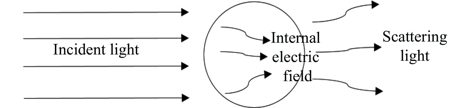
空气中的各种悬浮颗粒附着在镜面上形成表面污染物,这些颗粒污染物可近似视作球形粒子,进而可以用米氏理论来对镜面污染物的吸收特性进行定量分析。污染粒子的吸收主要来源为光照射在粒子上引起粒子内部电场的调制。如图1所示,单色平面光照射在颗粒上,入射光除了发生散射外,同时也会有部分能量在颗粒内部形成内电场,从而产生吸收特性。

Figure 1. Light absorption model for contaminated particles
由Mie理论[13]可知,单位振幅的入射光场照射颗粒体内后形成的内电场Eint平方的期望值可表达为:
式中:参量cn、dn为Mie吸收系数;mn和nn为与散射角函数相关的量,可分别表示为:
式中:x=ka/2用于表征颗粒的尺寸,为无量纲量,a为球形颗粒直径;m为相对折射率;z=x或z=mx。
利用公式(1)可计算单个颗粒在单位振幅下吸收值随粒子尺寸变化。图2给出了不同尺寸的污染颗粒内部的电场强度随粒子径向的变化。从图2可看出,粒子内部的电场强度随着颗粒径向尺寸的增大而减小,且内电场在颗粒中心处达到最大,而在边缘处最小;在材料折射率不变的情况下,不同尺寸颗粒内电场分布随径向尺寸的增大而明显减小,且在靠近边缘处的电场强度变化幅度会变小,并逐渐趋于平缓。

Figure 2. Internal electric field strength of contaminated particles with different sizes
进一步对公式(1)做球面积分,则可获得单个颗粒的吸收截面为:
式中:k=2π/λ为入射光波数,λ为入射光波长;ε″为该颗粒的相对介电常数的虚部(颗粒介质相对环境介质)。
由参考文献[14]可知,吸收截面与吸收的关系为:Qabs=4σabs/(πa2),进而可得到单个颗粒对光的吸收为:
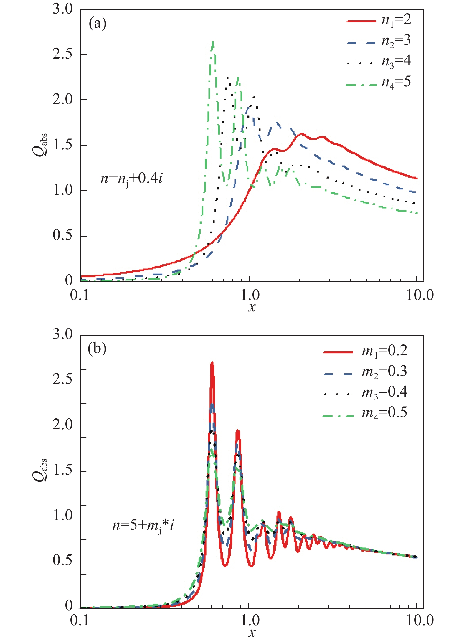
图3给出了在不同折射率实部及虚部情况下,污染颗粒吸收值随粒子尺寸的变化,如图3所示。

Figure 3. Absorption of polluted particles with different refractive index (a) real part and (b) virtual part
从图3(a)可以看出,随着折射率实部的增大,颗粒吸收曲线第一个峰值向左移动,且第一个峰值不断升高,曲线峰值的变化越来越大;从图3(b)可以看出,折射率虚部的变化只会导致曲线峰值的变化。并且,随着虚部的增大,其峰值逐渐减小,在靠近粒子大尺寸处,吸收变化逐渐趋于平缓,几乎不随粒子折射率虚部的变化而变化。
-
在实际应用中,通常使用表面洁净度来表示光学元件的污染情况。根据美国军用标准MIL-STD-209D,镜面的污染程度可用表面洁净度来表征。表面洁净度用一个数值描述,记作X1,表示每平方英尺镜面上大于该数值的颗粒数目刚好为1。该标准表明,镜面上粒子直径与其数量分布近似满足:
式中:X为颗粒直径;Na为元件表面每平方英尺上颗粒直径大于等于X的粒子数量(1 ft=0.305 m);C是归一化常量,对于清洁表面,C的值近似为0.926,对于未清洁表面,C的值近似为0.383。系数C对于清洁过和未清洁情况存在差异的主要原因在于对于未清洁的表面,系数0.383可能与观察结果更好地吻合,也就是说,来自空气的颗粒沉降产生了朝向大颗粒的尺寸分布,而表面清洁作用则在去除大颗粒方面比小颗粒更有效。因此,当使用MIL-STD指定清洁度水平时,将其限制在暴露于沉降物后已清洁的表面是很重要的。
图4给出了不同洁净度光学镜面的污染颗粒分布。分析图4可知,污染颗粒的尺寸越大,附着在镜面上的数量就越少。进一步地,C系数的选取对粒子数目影响也较大,在相同表面洁净度时,清洁和未清洁镜面的小尺寸颗粒数目大致相差2个数量级。然而,随着颗粒直径增大,清洁与未清洁的镜面污染颗粒之间的差距逐渐减小。

Figure 4. Distribution of polluted particles on optical mirrors with different cleanliness
根据公式(7)和(8),镜面的颗粒污染物吸收Aabs可写为:
式中:X为大于5的整数。将镜面各尺寸污染颗粒吸收值与镜面吸收总量的比值记作Ra(n),即:
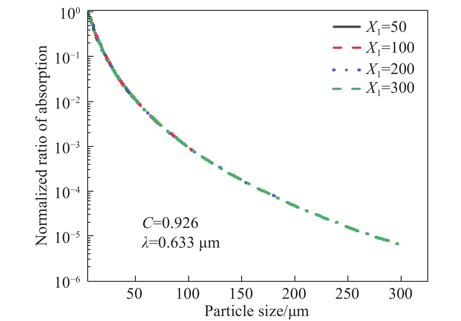
式中:Na(n)–Na(n+1)表示在n~(n+1) μm尺寸范围内镜面污染颗粒的数量。图5给出了不同洁净度镜面的Ra值随颗粒尺寸的变化曲线。由图5可知,随着颗粒尺寸的增大,其吸收系数呈下降趋势,经归一化处理后,其变化趋势不随表面洁净度等级的变化而变化。
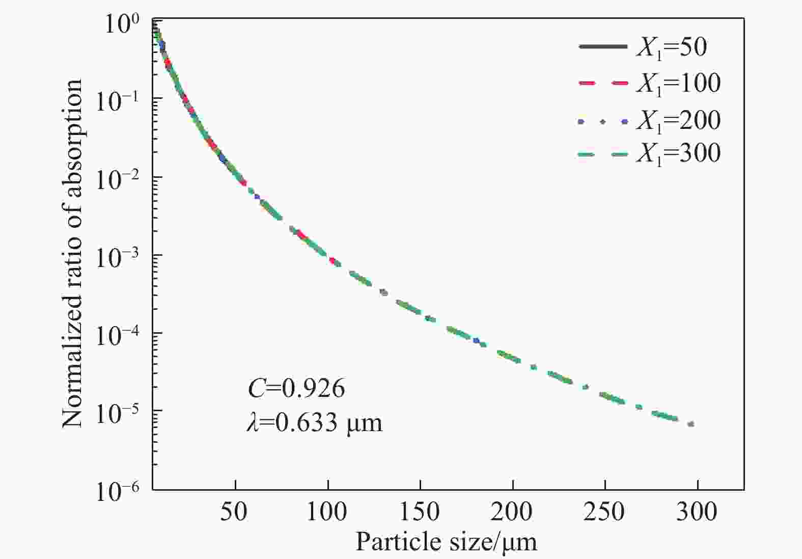
Figure 5. Ratio of absorptive value of particles of different sizes to total absorptive value of particles in different cleanliness
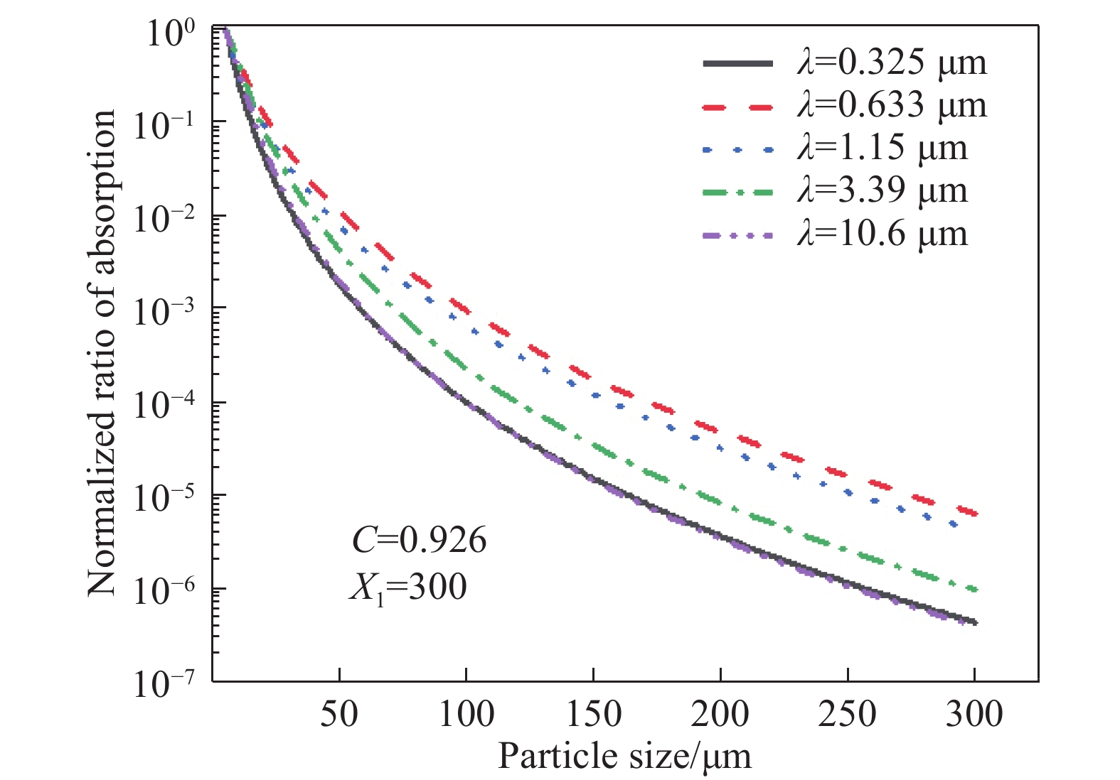
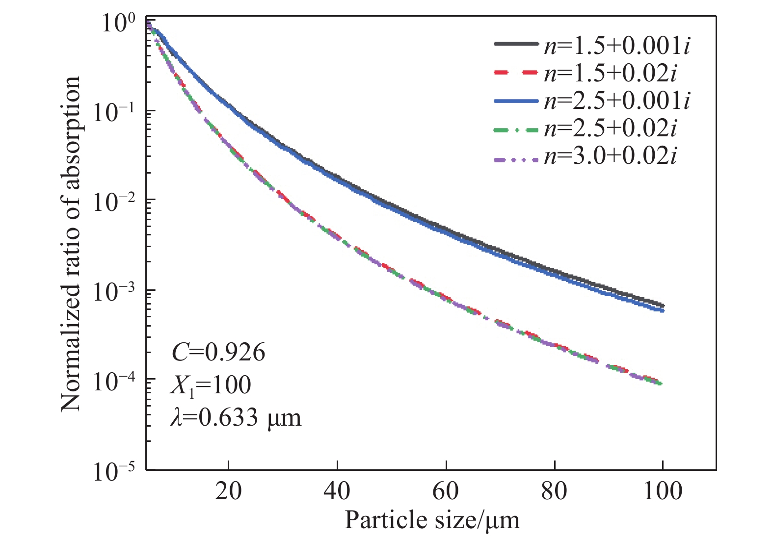
图6和图7分别给出了不同入射波长和灰尘不同折射率时,镜面不同尺寸灰尘的光吸收与镜面灰尘吸收总量的比值。其中,镜面洁净度X1=300,常数C=0.926。不同入射波长下镜面灰尘的折射率,如表1[15]所示。
由图6、7可知,镜面颗粒吸收主要集中在小尺寸的颗粒,随着颗粒尺寸增大,其吸收量呈下降趋势。
进一步从图7可以明显看出,当入射波长和表面洁净度一定的情况下,元件表面吸收几乎只与折射率虚部有关,虚部越大尺寸对吸收的影响越大,吸收比值变化梯度也越大。

Figure 6. Ratio of absorptive value of specular dust to total dust collection at different wavelengths

Figure 7. Ratio of polluted particle absorption to total absorption of specular particle with different refractive index
Item Value λ/μm 0.325 0.633 1.15 3.39 10.6 n 1.53+0.01i 1.53+0.000 5i 1.5+0.001i 1.5+0.02i 1.7+0.2i Table 1. Refractive index of dust at different wavelengths
-
空气洁净度是影响镜面洁净度的重要因素之一,为此需要明确不同空气洁净等级下,污染颗粒附着在镜面上的规律。美国联邦标准(FED-STD-209D)规定了空气洁净度等级标准:每立方英尺或每立方米空气中,直径大于或等于0.5 μm粒子的数目。空气中对的颗粒尺寸分布满足如下关系:
式中:X为颗粒的直径;Xc是空气洁净度等级;Nc是每立方英尺中颗粒直径大于等于X的粒子数量。基于大量关于粒子沉降速率的实验,Hamberg在文献中总结得出[16]:当洁净室的空气洁净度已知时,粒子在空气中的沉降规律可表示为:
式中:N为每平方英尺表面上直径大于5 μm的颗粒数量;t为元件曝露在洁净室空气中的时间,单位为天;ρ为洁净室相关因数,一般情况下ρ=2 851。结合公式(8)、(11)和(12)可得到镜面洁净度Xl与曝露时间t和空气洁净度Xc之间的关系,即:
由公式(13)可知,当元件工作面朝向和曝露在空气中的时间给定时,元件表面洁净度随着空气洁净度的增大而增大。
将公式(7)与(13)结合,可计算空气洁净度对镜面颗粒污染物吸收的影响,如图8所示(图中1 ppm=10−6)。

Figure 8. Effects of air cleanliness on specular particulate pollutant absorption
由图8可知,当曝露时间一定时,镜面吸收会随着空气洁净度等级的增大而增大,并且对元件表面吸收产生影响的主要因素是其折射率的虚部。
需要指出的是,Hamberg所考虑的镜面是水平放置时,但实际工作中的光学元件放置方式多种多样。由Tribble AC[17]等的研究可以得知,当光学元件垂直于水平面放置时,其工作表面上所附着的粒子数量大约是工作面水平向上放置时的十分之一,当元件的工作面是水平向下放置时,其工作表面附着的粒子数量则大约为工作面水平向上放置时的百分之一。图9给出了不同的放置条件下,元件表面吸收随时间的变化。
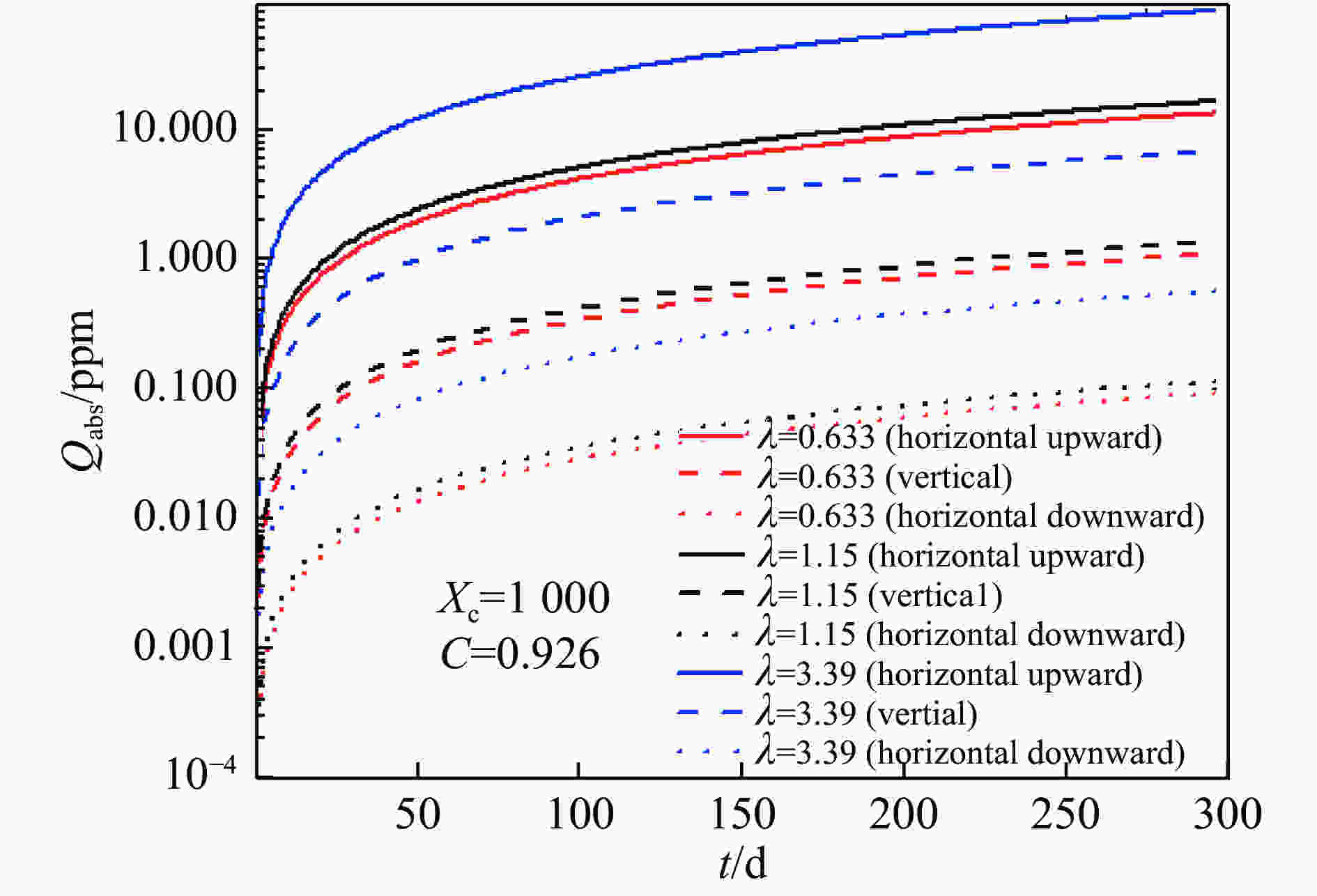
Figure 9. Influence of orientation of different working faces on absorption
分析图9可知,在空气洁净度一定的情况下,曝露时间越长,元件表面洁净度也越大,进而造成镜面吸收的增大。进一步比较不同波长的情况表明,颗粒吸收主要受折射率虚部的影响。此外,元件不同的放置方式也会对吸收产生很大影响。
在实际工作中,光学元件表面洁净度必须控制在某一范围,才能保证系统的性能保持基本不变,而当表面洁净度超过这个洁净度等级时,系统的工作性能将会迅速降低,此时系统所能容忍的洁净等级就是污染容限。当空气洁净度一定时,空气洁净度越大达到污染容限所用的时间也越短,进而,可以推测出达到污染容限所要的时间,并以此作为对元件进行清洗及维护所要求时间容限提供理论基础。
表2~4给出了入射光波长为0.633 μm和1.15 μm时,不同空气洁净度、工作面放置方式以及放置时间对元件表面吸收的影响。
Air class 1 000 10 000 100 000 Absorption(0.633 μm) 2.80×10⁻⁸ 1.92×10⁻⁷ 1.31×10⁻⁶ Absorption (1.15 μm) 3.46×10⁻⁸ 2.37×10⁻⁷ 1.62×10⁻⁶ Table 2. Absorption efficiency of different air cleanliness grades
Placement Horizontal downward surface Verticle surface Horizontal upward surface Absorption
(0.633 μm)1.94×10⁻¹⁰ 2.33×10⁻⁹ 2.80×10⁻⁸ Absorption
(1.15 μm)2.39×10⁻¹⁰ 2.88×10⁻⁹ 3.46×10⁻⁸ Table 3. Absorption efficient for different placement
Exposure time 1 d 10 d 20 d Absorption(0.633 μm) 2.80×10⁻⁸ 3.37×10⁻⁷ 7.13×10⁻⁷ Absorption(1.15 μm) 3.46×10⁻⁸ 4.16×10⁻⁷ 8.80×10⁻⁷ Table 4. Absorption efficiency at exposure times
由表2~4可以看出,空气洁净度等级越高,工作面朝向上,放置在空气中的时间越长时,空气中的颗粒沉积在元件表面的数量也越多,这样会致使元件表面吸收系数越大。其中,光学元件的放置方式对表面吸收特性影响显著,使得元件表面吸收系数有量级上的差异。此外,不同入射波长对吸收的影响也有较大差异,分析其主要原因是不同波长时的污染颗粒折射率虚部的差异造成的。光学镜面污染颗粒的吸收属于界面微弱吸收,其吸收值相对较低。在参考文献[6]中,鲁江涛等通过热透镜法测量得到的界面吸收系数为10−7,论文表2~4中结果与其相近,说明模拟结果符合实际。需要指出的是,光学薄膜的吸收已达到10−5量级甚至更小,则此时镜面污染颗粒的吸收影响不可忽视。
-
基于Mie理论,结合元件表面污染粒子分布,分析了在不同空气洁净度等级、元件工作面放置方式以及在空气中的曝露时间对光学元件表面吸收特性的影响,进而计算出了光学元件表面的吸收系数。结果表明,在相同的放置时间和放置方式条件下,空气洁净度等级越高,元件表面的吸收越强。在空气洁净等级和放置时间不变的情况下,元件工作面为水平放置时,其表面污染颗粒沉积最多,其吸收率也最大;而工作面为垂直放置时,吸收率次之;在工作面为水平向下放置时,其吸收率最小。在相同的空气洁净度等级和工作面放置不变的条件下,元件在空气中放置的时间越久,表面的吸收率越大。需要指出的是,镜面污染颗粒的种类和规模均会受到镜面材料、镀膜材料和应用场景的影响,从而导致其吸收特性的变化。例如,参考文献[18]给出在街道灰尘以SiO2为主,在施工地区又以Fe2O3为主,其附着在镜面后吸收特性有所变化。
Analysis of absorption characteristics of polluted particles on optical mirrors
doi: 10.3788/IRLA202049.0414004
- Received Date: 2020-01-06
- Rev Recd Date: 2020-02-09
- Publish Date: 2020-04-24
-
Key words:
- absorption /
- optical elements /
- Mie theory /
- cleanliness
Abstract: Aiming at the particle contamination on the surface of optical components in practical work, based on Mie theory, the absorption of incident laser energy by polluted particles (mainly SiO2) in the air in sandy areas was discussed. In addition, the effects of air cleanliness, orientation of working face and placement time on the surface absorption characteristics of optical components were further analyzed. The results show that the higher the air cleanliness level is, the optical component face up and the longer exposure time are, would make the surface absorption of the optical component stronger. The research results can provide guidance for pollution control of optical system in practical applications.


 DownLoad: