


-
激光制导武器因其具有结构简单、制导精度高、效费比高等特点[1],在现代战争中得到了广泛应用。
角度欺骗干扰是对抗激光制导武器的一种方式,一般在被保护重点目标周围布设多个假目标,由激光告警系统敏感到来袭激光信号,由激光干扰机按一定功率发射相同参数的激光干扰信号至假目标,假目标反射激光干扰信号进入来袭激光制导武器导引头视场,诱偏激光半主动制导武器,从而达到保护重点目标的目的[2]。
目前国内关于角度欺骗干扰的干扰效果研究主要集中在两个方面:一方面从干扰信号的角度,包括干扰信号时间超前量和真假目标距离以及指示-干扰信号功率比[3-5]等角度研究不同参数条件对干扰成功概率的影响。另一方面,从假目标应用的角度,参考文献[6]分析了漫反射板假目标的布设位置、漫反射面的朝向和多个假目标布设的具体要求。参考文献[7]提出了通过压制系数确定假目标防护角的方法,得出在典型工作环境下,常用漫反射板假目标的防护角大于 79°的结论。参考文献[8]在信号压制系数的基础上分析了几种典型自然地物假目标的有效干扰空域。这些研究对漫反射板和自然地物假目标的布设和选择具有指导意义。但是从理论上分析防护角大小得出的假目标干扰空域不够直观,无法及时准确得到实际应用中处于不同方位、距离和姿态角下的假目标的有效干扰空域。
文中以角度欺骗干扰中所使用的漫反射板假目标为研究对象,建立漫反射板假目标干扰空域评估模型,以干扰距离作为干扰效果的评价指标,得到漫反射板假目标的有效干扰空域态势图,实现干扰效果评估可视化;可以根据漫反射板假目标的布设距离、方位及姿态改变以及气象条件实现漫反射板假目标干扰空域的实时评估。在训练和作战环境中能够根据假目标布站情况,对防护区内的假目标干扰空域进行分析判断,对干扰资源进行分配决策。
-
假目标干扰空域评估系统由主机、配套组件、云台组件及三脚架组成。其中配套组件包括1.064 μm窄带滤光片、30 dB和60 dB衰减片、遮光罩及观瞄组件等。系统主机主要由能量采集和测量分系统、图像采集分系统以及干扰空域评估分系统组成。其结构框图如图1所示。

Figure 1. Schematic diagram of false target interference airspace evaluation system
-
能量测量分系统由窄带滤光片、近红外光学系统、光电探测器、信号处理与峰值保持单元和能量测量单元组成。窄带滤光片用于对多波段光线的过滤,中心光波长为1.064 μm;近红外光学系统主要用于对激光光斑漫反射光学信号的光学放大;光电探测器将光信号转化为脉冲电流;信号处理与峰值保持单元对光电探测器输出的脉冲电流信号进行放大、采样、峰值保持等处理;能量测量单元测量出激光信号能量密度值。
实验时,由激光器发射模拟干扰激光至漫反射板假目标,漫反射激光信号经大气传输进入假目标干扰空域评估系统,由能量测量分系统采集激光能量并对系统镜前激光能量密度进行测量。
-
图像采集分系统由窄带滤光片、近红外光学系统、近红外CCD器件和图像实时采集组件组成。近红外CCD器件在近红外波段具有较高灵敏度,能够采集激光光斑信号;图像实时采集组件主要用于采集漫反射板假目标的视频图像。
测试时,该系统可实时显示漫反射板假目标在视野中的位置,可根据视频图像调整云台方位和俯仰,使该系统对准漫反射板假目标。并通过对漫反射板假目标图像的采集及后续处理,计算假目标与系统的距离与法向角,为后续的干扰空域评估提供数据。
-
干扰空域评估分系统由加固计算机和综合信息处理中心组成。综合信息处理中心包括实时处理软件、测试评估处理软件、后处理应用软件以及通信软件等部件。主要完成对激光空间能量测量、靶板目标参数解算、有效干扰空域数据生成和有效空域态势图生成。干扰测试评估系统具有实时性强,可视化效果好,操作简便等优点,能更直观地体现漫反射板假目标的干扰效果,快速对防区内的防护态势进行评估。
-
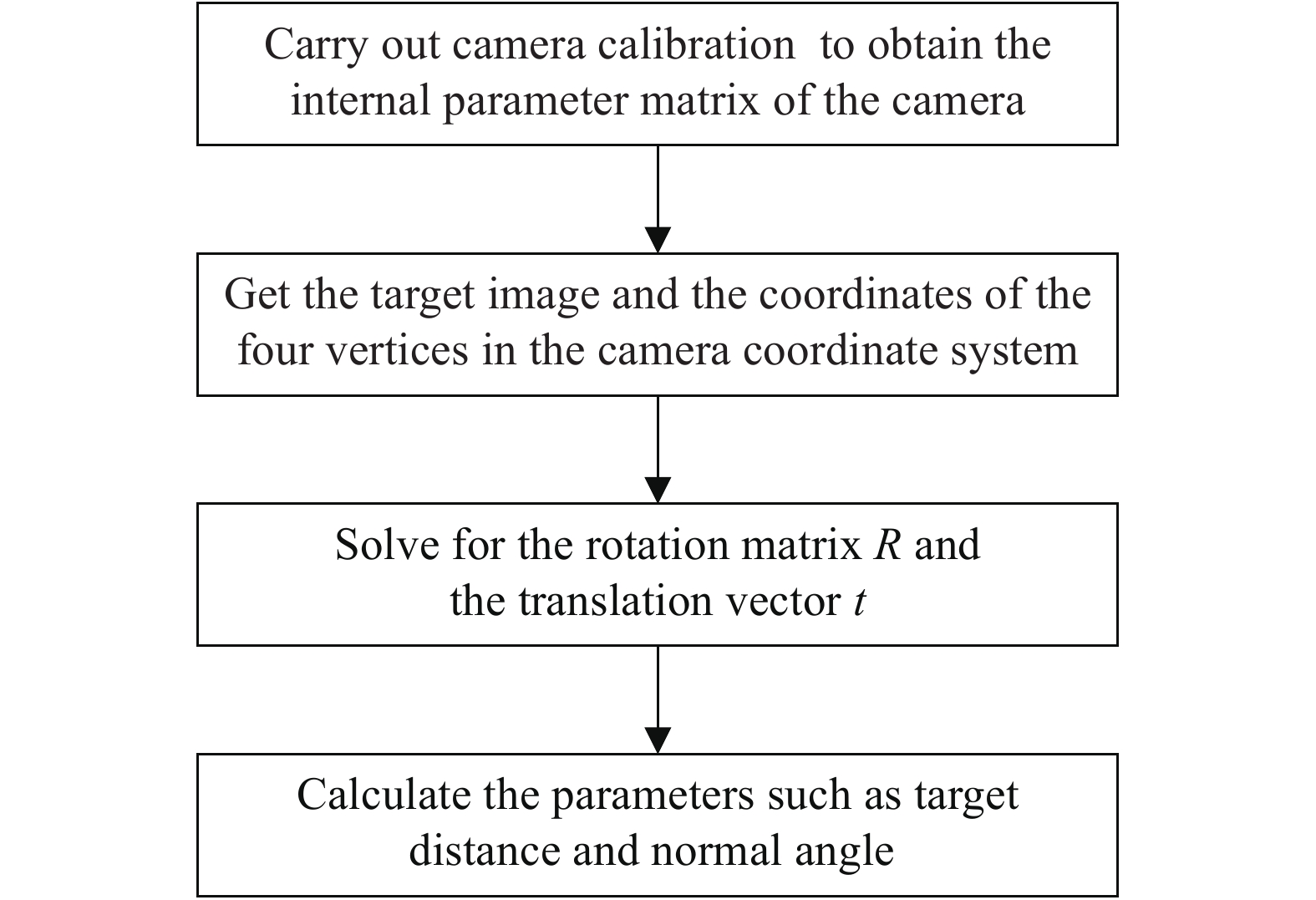
通过视频图像的实时变化调整云台,使设备对准靶板假目标,在设备的码盘上读出当前靶板相对设备的方位角并记录,从而确定当前位置下靶板假目标的大致方位角。但是,人工布设的靶板法线方向与系统设备视线方向无法做到完全一致,因此需要对靶板进行参数解算,计算靶板的法向角,用其方位分量和俯仰分量数据修正靶板假目标的朝向。另外,还需要测量靶板与系统设备的距离,为干扰空域评估提供数据。靶板目标参数解算是依据透视投影[9-10]原理,其解算流程如图2所示。

Figure 2. Flow chart of target board parameter calculation
-
在对假目标干扰空域进行评估的过程中,干扰距离是非常重要的一个指标。激光发射机发射激光干扰信号至漫反射板假目标上,激光干扰信号通过漫反射假目标反射后的能量随着反射方向与漫反射板假目标法线方向夹角的增大而呈余弦衰减。当在某一角度下反射能量衰减到与导引头最小可接收功率相同时,此时的距离即为干扰距离。可以通过漫反射板的反射模型以及对应天气的大气散射模型画出散射激光所充斥的空间,如图3所示。图中,
${\varphi _p}$ 为漫反射板假目标相对于设备法向角的俯仰分量,${\theta _i}$ 为入射光与漫反射板法线的夹角,${\theta _{rp}}$ 为漫反射板的法线和激光制导武器来袭方向夹角的俯仰分量,$\theta $ 为激光制导武器来袭方向与地面的夹角(威胁角)。
Figure 3. Schematic diagram of false target interference airspace
干扰空域的边界由干扰距离的大小所决定,可由以下公式计算[11]:
式中:
${E_{\rm{t}}}$ 为干扰激光单个脉冲能量;${\tau _{\rm{t}}}$ 为激光干扰源发射光学系统的透过率;${\tau _{{r}}}$ 为导引头接收系统的透过率;$\;\rho $ 为漫反射假目标的半球反射率;${\theta _r}$ 为反射光与漫反射板法线的夹角;${E_{{r}}}$ 为导引头接收的激光能量密度阈值;${u_{{a}}}$ 为大气的衰减常数;$R$ 为干扰距离;${R_1}$ 为干扰激光器与漫反射板之间的距离。 -
此次激光诱偏假目标系统实验中使用的是1.064 μm的激光,在传输过程中,大气衰减系数[12]
${u_{{a}}}$ 为:式中:
${V_m}$ 为大气能见度,km;q为与大气能见度有关的参数,q的取值如下: -
根据有效干扰距离计算公式可以得出漫反射板法线方向最大干扰距离计算公式为:
设系统接收光学系统透过率与导引头接收系统透过率相同,结合系统测量数据可以得到设备与假目标距离L和设备接收能量密度E的公式(5),其中
$\varphi $ 为假目标相对系统设备的法向角。结合公式(4)和(5)可以得出最大干扰距离Rmax与此系统所测量数据的公式(6)为:
根据公式(1)可得出不同
${\theta _r}$ 下的干扰距离的公式(7)为:反射角
${\theta _r}$ 在空间中存在方位角分量${\theta _{ra}}$ 和俯仰角分量${\theta _{rp}}$ 。其中${\theta _{ra}}$ 的取值范围为假目标正向所对应的半球空间,即[0°,180°]。${\theta _{rp}}$ 取值为:假设激光与地面平行入射到假目标上,则此时入射角
${\theta _i}$ 与$ {\varphi _p} $ 相等,公式(8)可以由公式(9)表示:由此可以得出不同威胁角和漫反射板倾角下的激光干扰空域,由公式(10)表示:
如已知单个漫反射板假目标相对设备法向角的俯仰分量,就可以得到其在不同威胁角下、不同方位上的干扰距离,不同方位距离数据合成单个假目标的干扰空域,多个假目标干扰空域合成得到多假目标干扰空域态势图。
-
干扰空域评估实验需要用到激光目标指示模拟器、漫反射板假目标和干扰空域评估系统等设备,具体实验示意图如图4所示。

Figure 4. Schematic diagram of the interference airspace evaluation experiment
实验步骤如下:
(1)将3个漫反射板按照一定距离和方位摆放在干扰空域评估系统的0°,120°,240°三个方向上,由激光目标指示模拟器发射模拟“干扰激光”,照射在其中一个漫反射板假目标上。
(2)利用干扰空域评估系统设备上的观瞄望远镜来瞄准目标,通过调整云台方位旋钮和俯仰旋钮控制干扰空域评估系统设备对准目标,读出此时云台上码盘的方位角数据。
(3)通过评估系统设备对当前位置下的反射激光能量密度进行测量,通过对视频图像中靶板图像进行解算得到靶板距离和法向角方位分量、俯仰分量,再结合码盘方位角数据对漫反射板假目标的朝向进行精确修正。
(4)根据上一步所采集到的数据和干扰空域评估模型,对单个假目标干扰空域进行评估。
(5)重复以上步骤,对其他两块漫反射板假目标用不同功率的激光进行照射,对剩余假目标干扰空域进行评估。用不同功率干扰激光进行照射的目的是验证不同接收激光功率对假目标干扰空域大小的影响。在对整个布站区域的单个假目标测完之后,可以得到整个区域内所有假目标干扰空域的态势图。
-
实验中首先对三个方向上的反射能量密度进行测量,每一个方向上经过测量计算得到20组能量密度数据,最后计算每个方向上的能量密度平均值,得到的测量计算结果如表1所示。
Number Energy value in the 0°/J·mm−2 Energy value in the 120°/J·mm−2 Energy value in the 240°/J·mm−2 1 2.79×10⁻¹³ 2.24×10⁻¹³ 4.20×10⁻¹³ 2 2.77×10⁻¹³ 2.23×10⁻¹³ 4.15×10⁻¹³ 3 2.75×10⁻¹³ 2.22×10⁻¹³ 4.15×10⁻¹³ 4 2.75×10⁻¹³ 2.20×10⁻¹³ 4.14×10⁻¹³ 5 2.72×10⁻¹³ 2.20×10⁻¹³ 4.14×10⁻¹³ 6 2.72×10⁻¹³ 2.19×10⁻¹³ 4.11×10⁻¹³ 7 2.72×10⁻¹³ 2.18×10⁻¹³ 4.11×10⁻¹³ 8 2.71×10⁻¹³ 2.18×10⁻¹³ 4.10×10⁻¹³ 9 2.71×10⁻¹³ 2.18×10⁻¹³ 4.08×10⁻¹³ 10 2.71×10⁻¹³ 2.18×10⁻¹³ 4.08×10⁻¹³ 11 2.71×10⁻¹³ 2.17×10⁻¹³ 4.07×10⁻¹³ 12 2.69×10⁻¹³ 2.16×10⁻¹³ 4.07×10⁻¹³ 13 2.68×10⁻¹³ 2.15×10⁻¹³ 4.06×10⁻¹³ 14 2.68×10⁻¹³ 2.15×10⁻¹³ 4.06×10⁻¹³ 15 2.67×10⁻¹³ 2.15×10⁻¹³ 4.06×10⁻¹³ 16 2.66×10⁻¹³ 2.14×10⁻¹³ 4.04×10⁻¹³ 17 2.65×10⁻¹³ 2.14×10⁻¹³ 4.04×10⁻¹³ 18 2.65×10⁻¹³ 2.12×10⁻¹³ 4.04×10⁻¹³ 19 2.64×10⁻¹³ 2.12×10⁻¹³ 4.02×10⁻¹³ 20 2.64×10⁻¹³ 2.10×10⁻¹³ 4.02×10⁻¹³ Average 2.70×10⁻¹³ 2.17×10⁻¹³ 4.08×10⁻¹³ Table 1. Laser energy density measurement results
-
分别对三个方向上的靶板进行图像采集和参数解算,得到靶板的距离L和法向角
$\varphi $ 等参数,图像采集及参数解算结果如图5和表2所示。
Figure 5. Target board image
Azimuth/(°) Distance of target board L/m Normal angle azimuth component ${\varphi _a}$/(°) Normal angle pitch component ${\varphi _p}$/(°) 0 143.072 0.4 18.4 120 142.643 0.4 19.4 240 143.072 0.2 19.0 Table 2. Result of target board parameter calculation
结果显示,系统能够正确识别靶板目标并对其参数进行解算。其中,0°方向上的靶板目标与测试系统设备距离为143.072 m,靶板的法向角方位分量为0.4°、俯仰分量为18.4°;120°方向上的靶板目标与测试系统设备距离为142.643 m,靶板的法向角方位分量为0.4°,俯仰分量为19.4°;240°方向上的靶板目标与测试系统设备距离为143.072 m,靶板的法向角方位分量为0.2°,俯仰分量为19.0°。由于三块靶板的法向角方位分量较小,为方便计算,靶板的法向角
$\varphi $ 近似取为${\varphi _p}$ 。 -
根据3.2.1及3.2.2节所测量和解算的数据,对三个方向的假目标进行干扰空域评估。假设气象条件为一般,能见度为15 km,导引头所接收的能量密度阈值为1.0×10⁻¹⁵ J/mm2,分别得到三个方向假目标的干扰空域态势图。态势图给出了20°、45°和70°威胁角下的干扰空域,如图6(a)~(c)所示。漫反射板实际的干扰空域应是一个近似半球空间,图6所绘制的干扰空域是三个威胁角平面下截取的干扰范围。在完成对三个单目标干扰空域评估后,通过空间合成可完成对三个目标联合布站干扰空域的评估,如图6(d)所示。

Figure 6. Situation diagram of interfering airspace
态势图结果显示,三个方向的靶板在45°威胁角下的干扰最大距离分别为2045.6 m、1860.4 m和2470.0 m,可见单个目标的干扰空域大小与系统接收能量有关,接收能量越强,干扰距离越大。由于文中实验使用的激光目标指示器功率较小,因此假目标的干扰空域较小,在实际应用中假目标干扰空域的范围会随干扰激光功率的增加而增大。三个靶板的法向角俯仰分量最大为19°,均不超过20°,比较同一个靶板在不同威胁角下的干扰空域可以看出,当威胁角与靶板法向角俯仰分量的角度差越大,即武器来袭方向与漫反射板的法线方向夹角越大时,靶板的干扰空域越小。因此,当武器来袭方向与靶板的法线方向相同时,靶板的干扰效果最好,干扰空域可以达到最大。多目标干扰空域合成可以实现对整个防区内的假目标干扰态势的评估。
-
文中设计了一种假目标干扰空域评估系统,分析了系统的组成及关键技术,以干扰距离为主要指标,提出了一种漫反射板假目标干扰空域评估模型,并依此模型得到干扰空域态势图。依托此系统开展了干扰空域评估实验,达到了预期的效果,该评估系统具有实时性强、可视化程度高等特点,该系统大大丰富和完善了假目标干扰性能检测地评估手段,为训练和作战条件下重点目标防护提供技术支持和决策建议。
Research on the technique of interference airspace evaluation of laser angle deception false targets
doi: 10.3788/IRLA20210008
- Received Date: 2021-01-04
- Rev Recd Date: 2021-03-19
- Publish Date: 2021-09-23
-
Key words:
- angle deception interference /
- diffuse reflector /
- interference distance /
- interference airspace
Abstract: Aiming at the problems of lack of instantaneity and low visualization in laser angle deception interference evaluation, the evaluation system for the airspace interference of false targets of laser angle deception interference was constructed. Firstly, the distance and attitude parameters of the false target of the diffuse reflector were calculated according to the principle of perspective projection, and then the interference mechanism of the false target of the diffuse reflector was analyzed and based on the interference distance, the airspace evaluation model of the false target interference of the diffuse reflector was derived. Finally, experiments were designed relied on the system. In the experiment, the diffuse reflector installed in the direction of 0°, 120° and 240° of the equipment was irradiated by lasers with different powers. Then the evaluation system equipment was used to measure the parameters of the three diffuse reflectors, and the average energy density received by the system were 2.70×10⁻¹³ J/mm2, 2.17×10⁻¹³ J/mm2 and 4.08×10⁻¹³ J/mm2 respectively. The maximum interference distance under 45° threat angle were 2045.6 m, 1860.4 m and 2470.0 m, respectively. Finally, the relationship between the size of the jamming airspace and the threat angle of the weapon was analyzed, and the situation maps of the interference airspace of the false target under the threat angles of 20°, 45° and 70° were obtained. The experimental results show that, under the experimental conditions, the interference airspace range of the false target increases with the increase of the energy received by the system. The smaller the angle between the attack direction of the weapon and the normal direction of the diffuse reflector, the greater the interference airspace. Taking the interference distance as the evaluation index, the interference airspace of the diffuse reflector false target is evaluated, which can provide technical support for the interference effect evaluation of false target.


 DownLoad: