


-
现代战争中,对远距离目标的探测和识别是实现精确打击的先决条件。通常,搜索、探测目标时观瞄系统处于短焦、宽视场状态,识别、跟踪目标时观瞄系统处于长焦、窄视场状态。定焦镜头无法同时满足上述两种需求,变焦镜头可通过短焦和长焦的切换实现探测功能和识别功能的切换[1-3]。变焦系统可分为机械补偿变焦系统和光学补偿变焦系统。机械补偿变焦系统一般由前固定组、变焦组、补偿组、后固定组组成,变焦过程变焦组作线性运动,补偿组作非线性运动,通过机械凸轮使像面在整个变焦过程中维持稳定,但这种系统结构复杂,空间尺寸较大,光轴一致性难以保证;和机械补偿变焦系统相比,光学补偿变焦系统只需变焦组轴向移动即可实现两档变焦,无需补偿组,具有结构简单、紧凑,光轴一致性容易控制的优势[4-7]。对于宽视场实现目标探测、窄视场实现目标识别的应用场景,双视场光学变焦系统优势明显。
目前,国外变焦镜头设计的主要研究方向[8-9]是使用液体透镜、电动变焦透镜等改变光学系统局部光学元件的焦距以实现整个光学系统焦距的变化,从而避免元件的轴向移动,实现系统的紧凑化。但以上技术目前成熟度和可靠性不足,使用条件和范围受限;国内变焦镜头设计的研究[1-2, 6, 10-11]主要停留在针对720P及以下的标清相机,设计过程也很少论及作用距离与环境照度、能见度、相机最低工作照度等参数的关系。文中采用将短焦和长焦光阑设置在不同位置的光阑位置切换方案,针对1080P高清相机,根据设计指标,考虑最低环境照度下的正常使用,设计一款短焦焦距为32 mm、长焦焦距为126 mm的紧凑型双视场可见光镜头,分别用于搜索、探测和识别、跟踪目标。
-
某光电观瞄系统的光学相关技术指标见表1。
Parameters Specifications Horizontal field angle/(°) ≥12(Detection)≥3(Recognition) Dimension of target/m 4.6×2.3(Equivalent length: 3.3) Operating range/km ≥5 Atmospheric visibility/km ≥10 Ambient illuminance/lux ≥300 Distortion ≤0.5%(Detection) Table 1. Related optical indicators of observing and sighting system
-
设所选相机有效像元数为M(H)×N(V),像元尺寸为a×a,单位为μm,短焦焦距为
${f'_S}$ ,长焦焦距为${f'_L}$ ,单位为mm。短焦状态和长焦状态对5 km处目标成像所占像元数N1和N2分别可以表示为:根据Johnson准则,以95%概率探测和识别目标时,所需条带周期数分别约为2和8[12],对应所需像素数分别为4和16,根据技术指标需满足:
设短焦状态水平视场角为
${\omega _{xS}}$ ,长焦状态水平视场角为${\omega _{xL}}$ ,根据技术指标需满足:将公式(3)~(4)分别代入公式(5)~(6)可知,M应满足不小于1274。720P相机水平方向有效像元数为1280,为预留足够的设计余量保证视场和作用距离都满足要求,在该设计中选用1080P相机,其具体参数如表2所示(1 in=2.54 cm)。
Parameters Specifications Image sensor 1/1.9 in CMOS image sensor Valid pixels 1 920(H) ×1080(V) Pixel size 3.75 μm(H)×3.75 μm(V) Minimal illumination 0.1 lx Table 2. Related specifications of the CMOS image sensor used
将
$M = 1\;920$ ,$N = 1\;080$ ,$a = 3.75$ μm代入公式(3)~(6)可得:光学系统的变倍比应介于2.7~6之间,为保证足够设计余量,取中间值较为合适。
-
F数是光学系统的重要指标之一,其数值大小与理论分辨率、像面照度密切相关。F数越小,光学系统的理论分辨率越高,像面照度越强,但作为F数倒数的相对孔径会增大,从而提升设计难度。以下分别根据相机像元尺寸和相机最低工作照度计算F数的取值范围。
通常,艾里斑半径和直径的倒数分别被认为是光学系统的截止频率和中间频率。在确定F数时,艾里斑直径所占像元数为1~2个[10]。在空气中,物镜的艾里斑直径可以表示为[13]:
艾里斑占1个像素时,可得:
将D光波长0.5893 μm代入公式(10)可得
$F = $ $ 2.61$ 。同理,当艾里斑占2个像素时,计算可得$F = $ $ 5.22$ 。因此,F数取值不宜大于5.22,且越小越好。光学系统像面照度EI可以表示为[14]:
式中:ET表示观察目标附近的环境照度,单位为lx;γ表示目标表面对可见光的反射率;T0表示光学系统的透过率;α表示大气衰减系数,单位为km−1;R表示目标与光学系统的距离,单位为km。在该设计中,ET为300 lx,γ取0.2,T0取0.8,R为5 km。α可以表示为[15]:
式中:V为大气能见度,在该设计中为10 km,可求得α为0.3912 km−1。已知所选相机的最低工作照度Ed为0.1 lx,因此必须满足:
可求得
$F \leqslant 4.12$ 。综合考虑相机像元尺寸和最低照度,F数要满足不大于4.12。
-
对于双视场光学系统,变焦组轴向移动实现长焦状态和短焦状态切换,满足物像交换原则[5],以下分析前固定组和变焦组。设M为变倍比,短焦状态变焦组对前固定组的轴向放大率
${\;\beta _{2S}}$ 可以表示为:长焦状态变焦组对前固定组的轴向放大率
${\;\beta _{2L}}$ 可以表示为:设变焦组的焦距为
${f_2}^\prime $ ,根据高斯公式可得:焦距切换时,变焦组的移动量可以表示为:
分析公式(17)可知,当变倍比恒定时,
$\Delta $ 与${f_2}^\prime $ 的绝对值成正比,为缩短切换时间,${f_2}^\prime $ $ {f}_{2}' $ 的绝对值要尽量小。 -
依据以上计算、分析,取光学系统的变倍比为4,运用高斯公式计算光学系统的初始结构,并在光学设计软件Code V中用理想透镜进行模拟,参考光学设计手册和相关专著[16-17]对光学系统进行复杂化设计,同时约束光学总长、最大通光孔径、变焦组焦距等参数,并选用CDGM玻璃库提供的普通光学材料。优化过程首先采用常规的光阑位置固定方案,得到光学总长为170 mm,最大通光孔径为Φ52 mm,变焦行程为62.60 mm的双视场光学系统,图1、图2分别为焦距32 mm、焦距126 mm光学系统图,表3为具体参数。
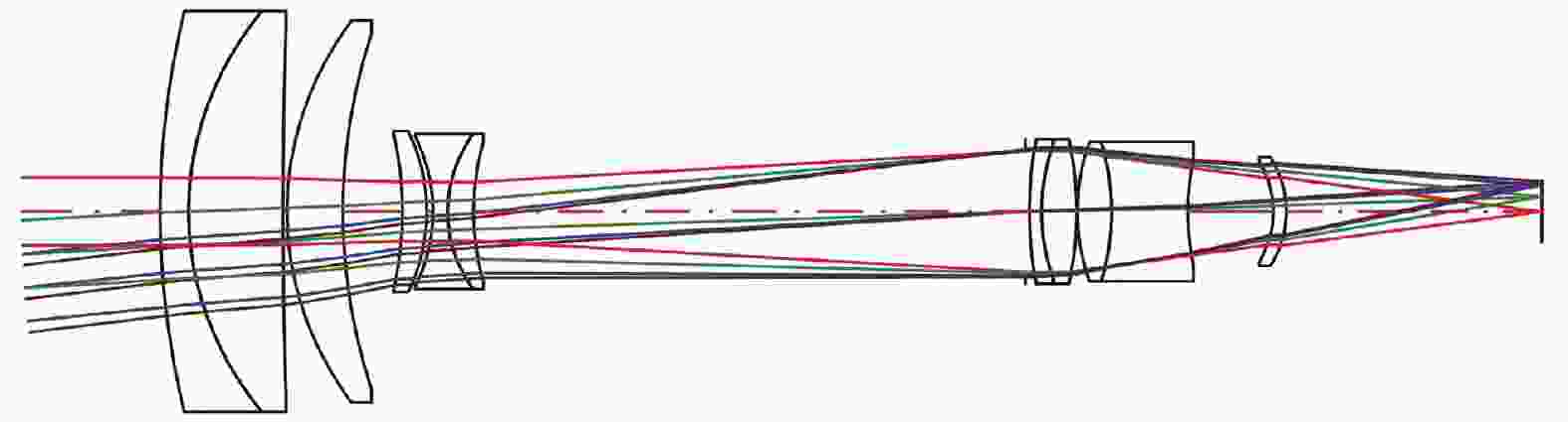
Figure 1. Diagram of 32 mm focal length optical system with fixed stop position scheme
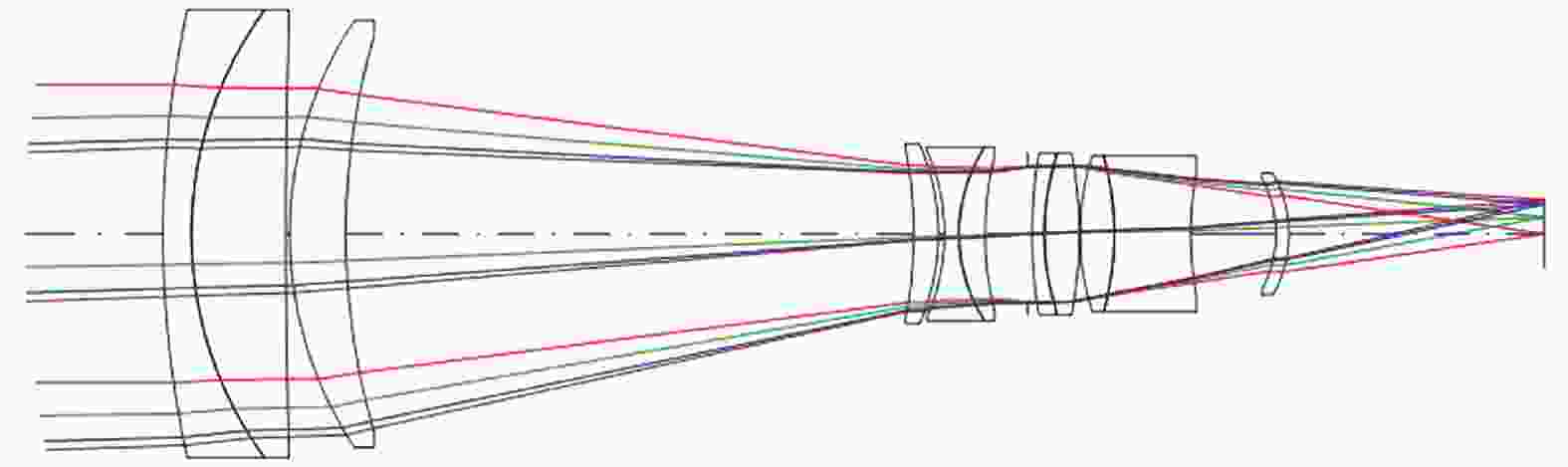
Figure 2. Diagram of 126 mm focal length optical system with fixed stop position scheme
Parameters Short focal length Long focal length Spectral range/nm 486 - 656 Effective focal length/mm 32 126 F number 3.5 Object space angle/(°) 12.96 × 7.22 3.24 × 1.82 Total optical length/mm 170 Maximal effective aperture/mm Φ52 Focal length of zoom group/mm -42.30 Zoom stroke/mm 62.60 Table 3. Specific parameters of optical system with fixed stop position scheme
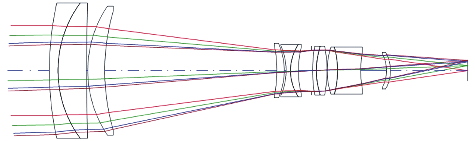
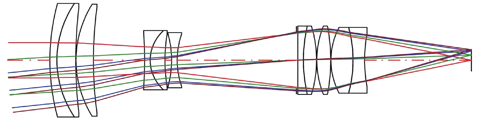
为压缩轴向尺寸、径向尺寸及变焦行程,尝试将短焦光阑、长焦光阑设置于不同位置,此时短焦状态和长焦状态的F数不再相同。为保证光阑设置有效,短焦状态在长焦光阑位置的通光孔径不应大于长焦状态的光阑孔径;同理,长焦状态在短焦光阑位置的通光孔径不应大于短焦状态的光阑孔径。根据相对孔径的定义,将长焦光阑设置于第1片透镜前,使得光学系统的最大通光孔径为长焦焦距与对应的F数的比值,将短焦光阑设置于其他位置以提升像质和压缩轴向尺寸。除两个光阑位置外,所有透镜的通光孔径选取长焦状态和短焦状态的最大值以保证无拦光。优化过程控制短焦焦距、长焦焦距与光阑位置固定方案一致,得到光学总长为150 mm,最大通光孔径为Φ42 mm,变焦行程为35.97 mm的双视场可见光镜头,图3、图4分别为焦距32 mm、焦距126 mm光学系统图,表4为具体参数。焦距32 mm对应的水平视场角13.18°,焦距126 mm对应的水平视场角3.28°,满足指标要求。

Figure 3. Diagram of 32 mm focal length optical system with switchable stop position scheme
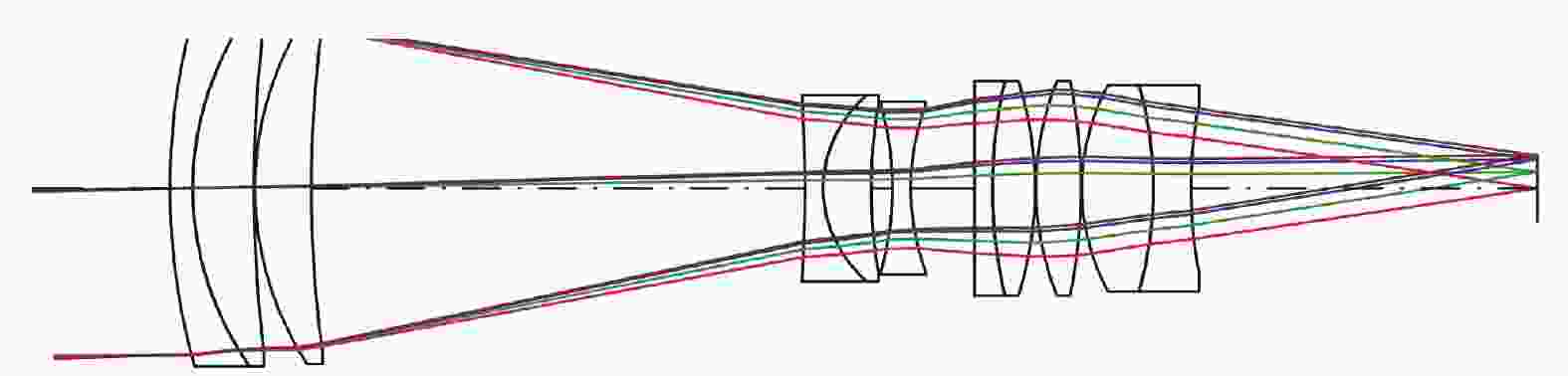
Figure 4. Diagram of 126 mm focal length optical system with switchable stop position scheme
Parameters Short focal length Long focal length Spectral range/nm 486 - 656 Effective focal length/mm 32 126 F number 2.3 3 Object space angle/(°) 13.18 × 7.30 3.28 × 1.84 Total optical length/mm 150 Maximal effective aperture/mm Φ42 Focal length of zoom group/mm -24.29 Zoom stroke/mm 35.97 Table 4. Specific parameters of optical system with switchable stop position scheme
与常规的光阑位置固定方案对比,光阑位置切换方案实现光学总长12%、最大通光孔径19%、变焦行程43%的压缩和相对孔径34%、14%的提升。
光阑位置切换方案选用的材料为:H-ZLaF4LA、H-ZPK1A、H-ZPK5、H-ZLaF53B、H-ZLaF90、H-ZF7LA、H-FK61和H-LaK52。第1~3片透镜构成前固定组,整体具有正光焦度;第4~6片透镜构成变焦组,整体具有负光焦度,通过其轴向位置切换实现短焦状态和长焦状态的切换;第7~11片透镜构成后固定组,整体具有正光焦度,选用P值相近而
$\nu $ 值不等的H-FK61和H-LaK52胶合实现复消色差。短焦光阑位于第7片透镜前,长焦光阑位于第1片透镜前。光阑位置切换方案可与光阑位置固定方案采用相同的机械切换方式,即电机驱动丝杠,带动变焦组轴向移动实现焦距切换,光电码编码器记录位置。 -
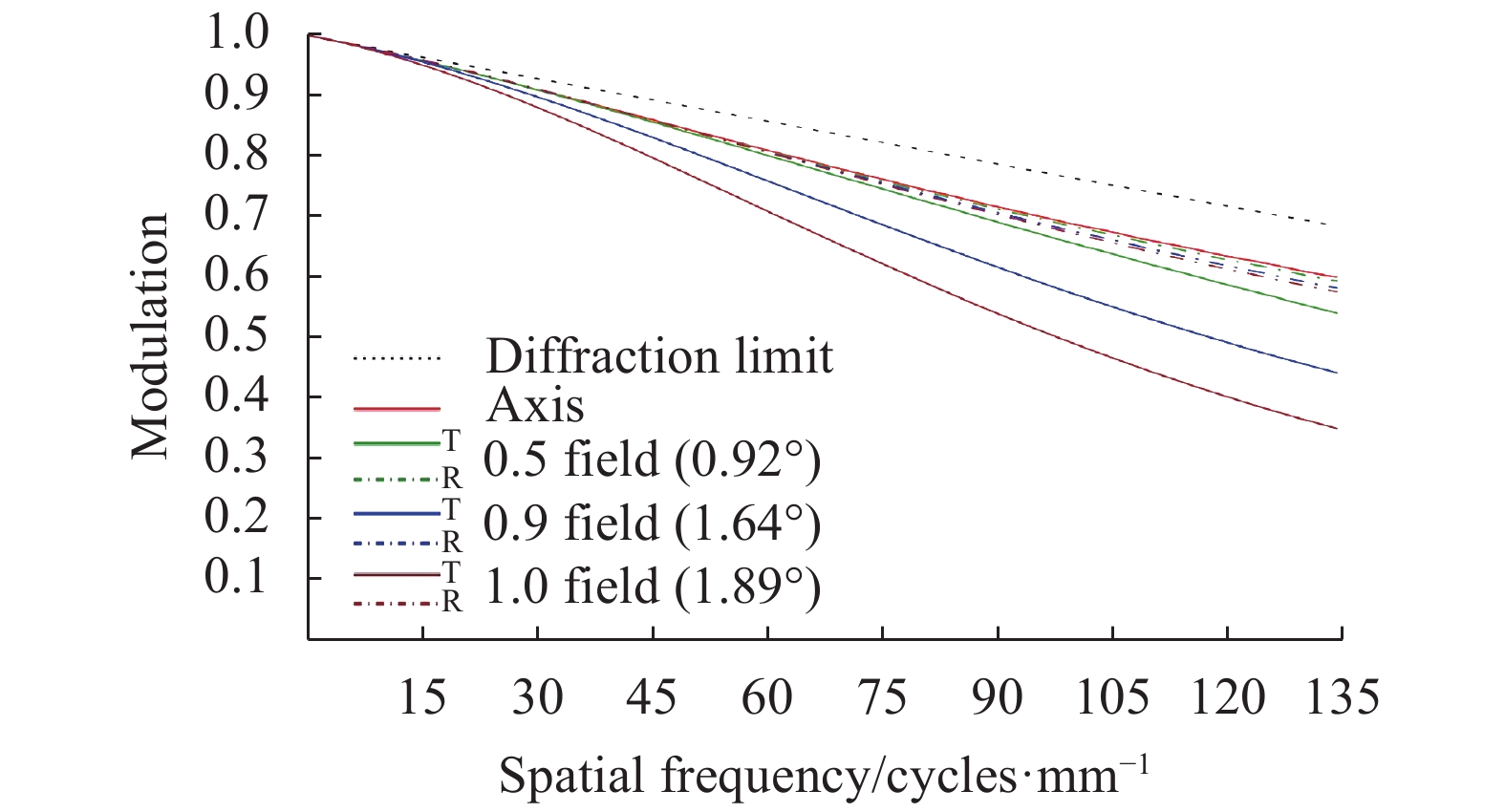
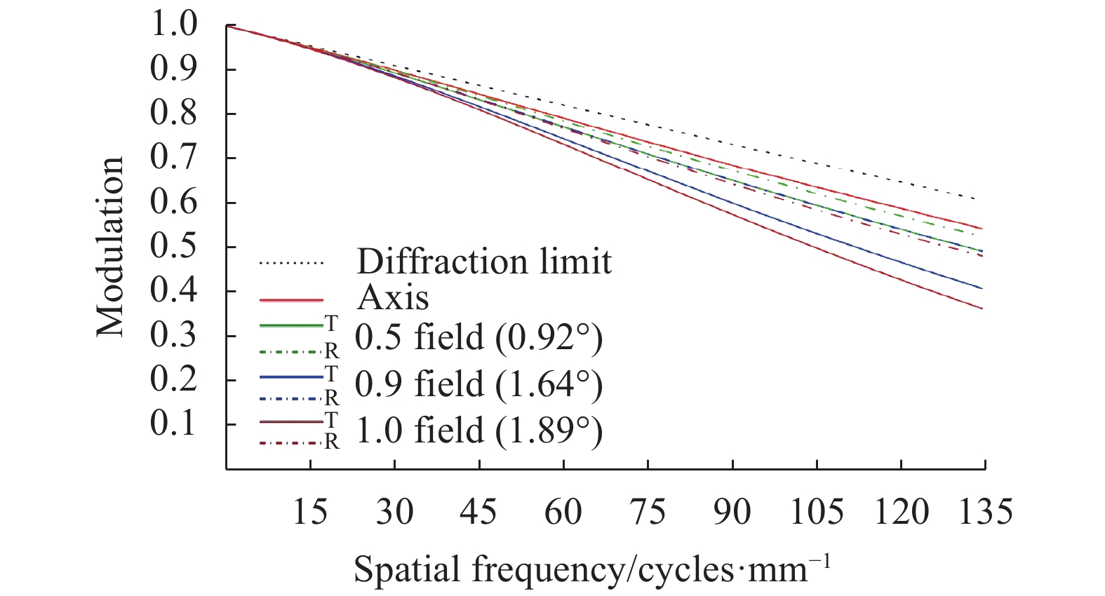
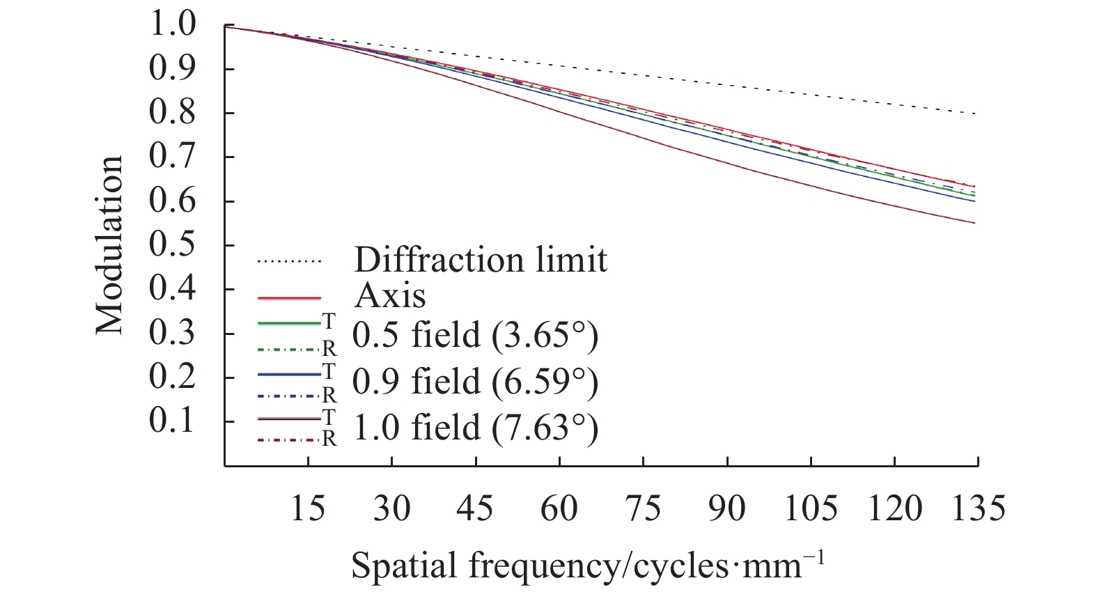
MTF是目前公认的最能充分反映光学系统实际成像质量的评价指标[5],以下对比光阑位置固定方案和光阑位置切换方案的MTF曲线,并选取
$\dfrac{1}{{2a}} \approx $ $ 135\; {\rm{cycles}}/{\rm{mm}}$ 作为特征频率。图5、图6分别为光阑位置固定方案焦距32 mm、焦距126 mm MTF曲线,最上方虚线表示衍射极限。从图中可以看出,为保证焦距126 mm各视场MTF均大于0.45,焦距32 mm子午方向边缘视场MTF已经降至0.3以下。图7、图8分别为光阑位置切换方案焦距32 mm、焦距126 mm MTF曲线。从图中可以看出,除子午方向边缘视场外,各视场MTF曲线均较为平滑,且全视场MTF均大于0.45,像质良好。

Figure 5. MTF curves of 32 mm focal length with fixed stop position scheme
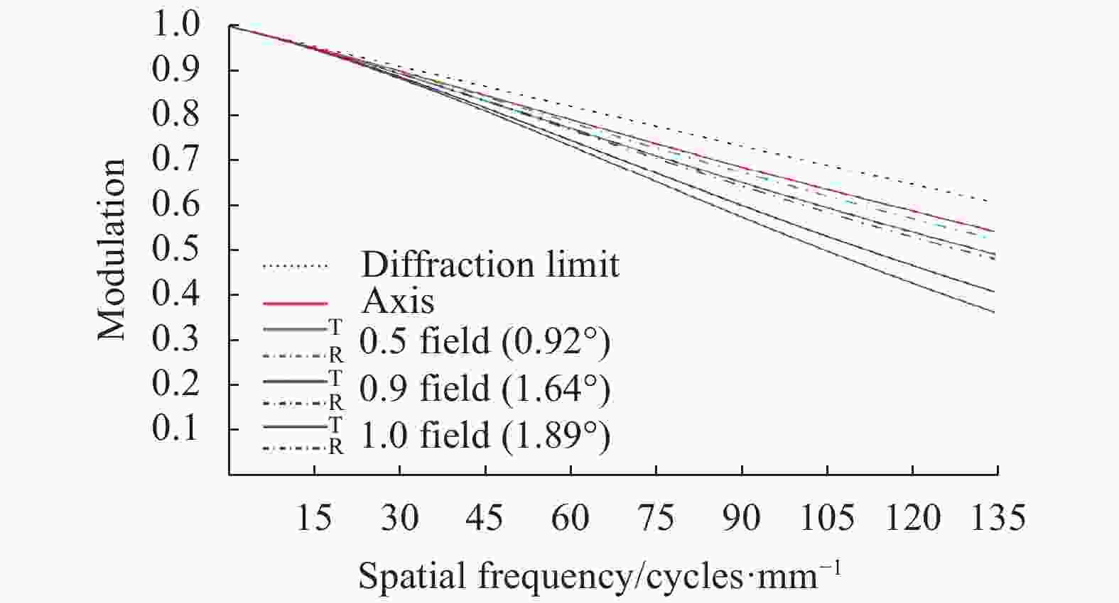
Figure 6. MTF curves of 126 mm focal length with fixed stop position scheme
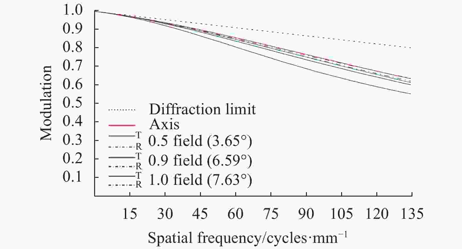
Figure 7. MTF curves of 32 mm focal length with switchable stop position scheme

Figure 8. MTF curves of 126 mm focal length with switchable stop position scheme
与光阑位置固定方案相比,光阑位置切换方案不仅可以实现结构紧凑,变焦行程更短,相对孔径更大,综合像质也能够明显提升,故最终选用光阑位置切换方案。以下分析光阑位置切换方案的畸变曲线和点列图。
图9、图10分别为光学系统焦距32 mm、焦距126 mm畸变曲线。从图中可以看出,焦距32 mm边缘视场畸变最大,约为−3.4%,焦距126 mm边缘视场畸变最大,约为−0.26%,满足指标要求。
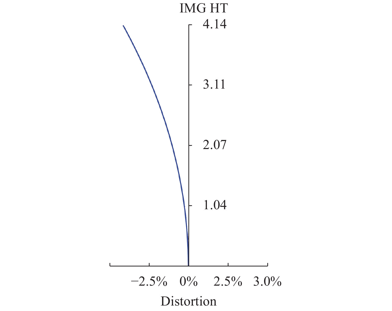
Figure 9. Distortion curve of 32 mm focal length
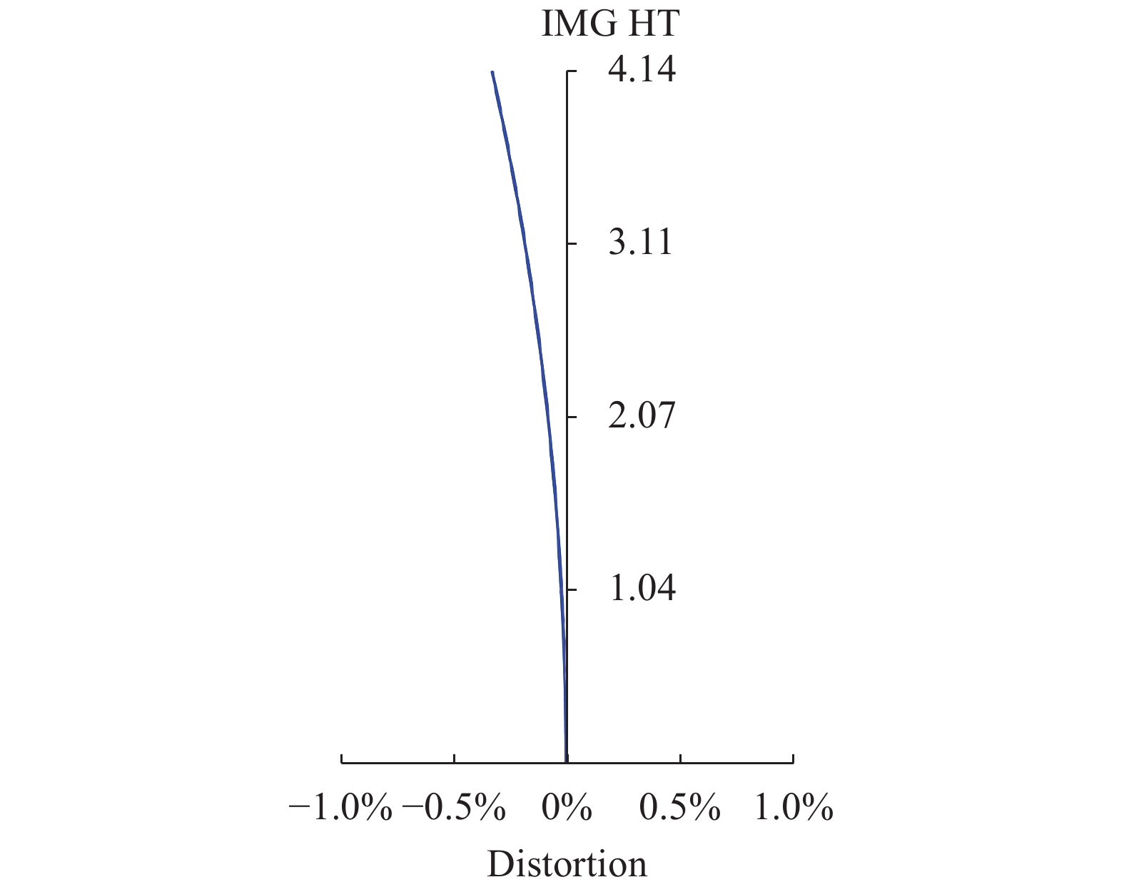
Figure 10. Distortion curve of 126 mm focal length
图11、图12分别为光学系统焦距32 mm、焦距126 mm点列图。从图中可以看出,焦距32 mm边缘视场点列图的RMS直径为3.85 μm,焦距126 mm边缘视场点列图的RMS直径为4.01 μm,略大于相机像元尺寸。其余视场点列图的RMS直径均小于相机像元尺寸,整体像质良好。图中100%表示光线追迹所得实际光斑尺寸。
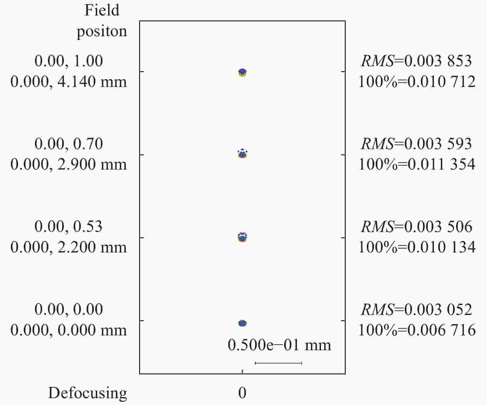
Figure 11. Spot diagrams of 32 mm focal length
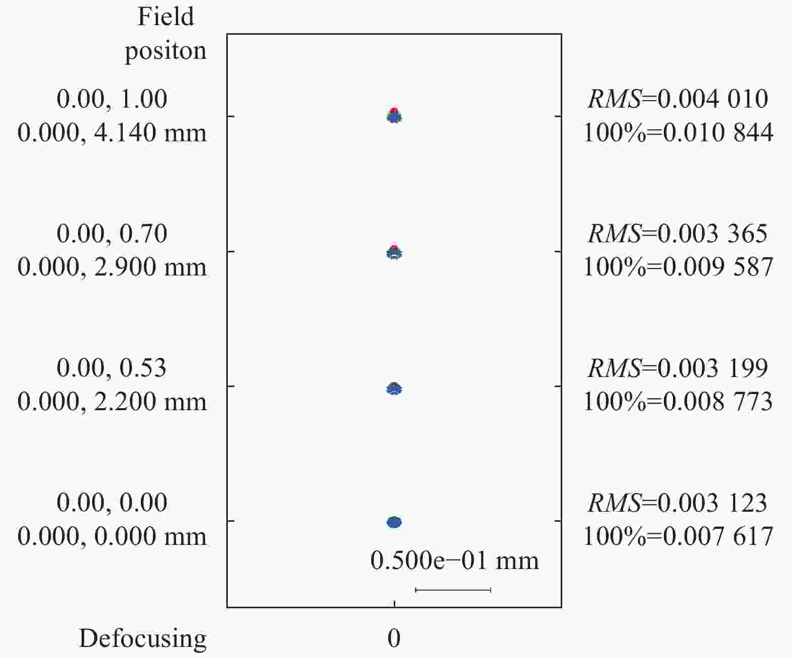
Figure 12. Spot diagrams of 126 mm focal length
-
光学系统中材料的特性误差、元件的加工和装配误差会导致性能下降。该设计中,按照目前国内工艺水平拟定初始公差范围,设置变焦组和像面的轴向移动作为补偿器。选用复色MTF作为评价指标,利用反转灵敏度分析生成具体公差,要求在
$135\;{\rm{cycles}}/{\rm{mm}}$ 处全视场MTF大于0.3的概率达到90%以上。表5、表6、表7所示为材料公差、加工公差、装调公差,公差分析曲线如图13、图14所示,满足设计要求。Items Value Refractive index/mm 1×10⁻⁴-5×10⁻⁴ Abbe-number 0.3%-0.5% Homogeneity/mm 2×10⁻⁶-5×10⁻⁶ Table 5. Material tolerances
Items Value Fringe power/λ 1-2 Surface irregularity/λ 0.2-0.5 Central thickness/mm 0.02-0.05 Wedge/mm 0.005-0.01 Table 6. Manufacturing tolerances(λ=546.1 nm)
Items Value Airspace/mm 0.02-0.05 Tilt/rad 0.0005-0.001 Decenter & Roll/mm 0.02-0.05 Table 7. Alignment tolerances

Figure 13. Curves of tolerance analysis at short focal length
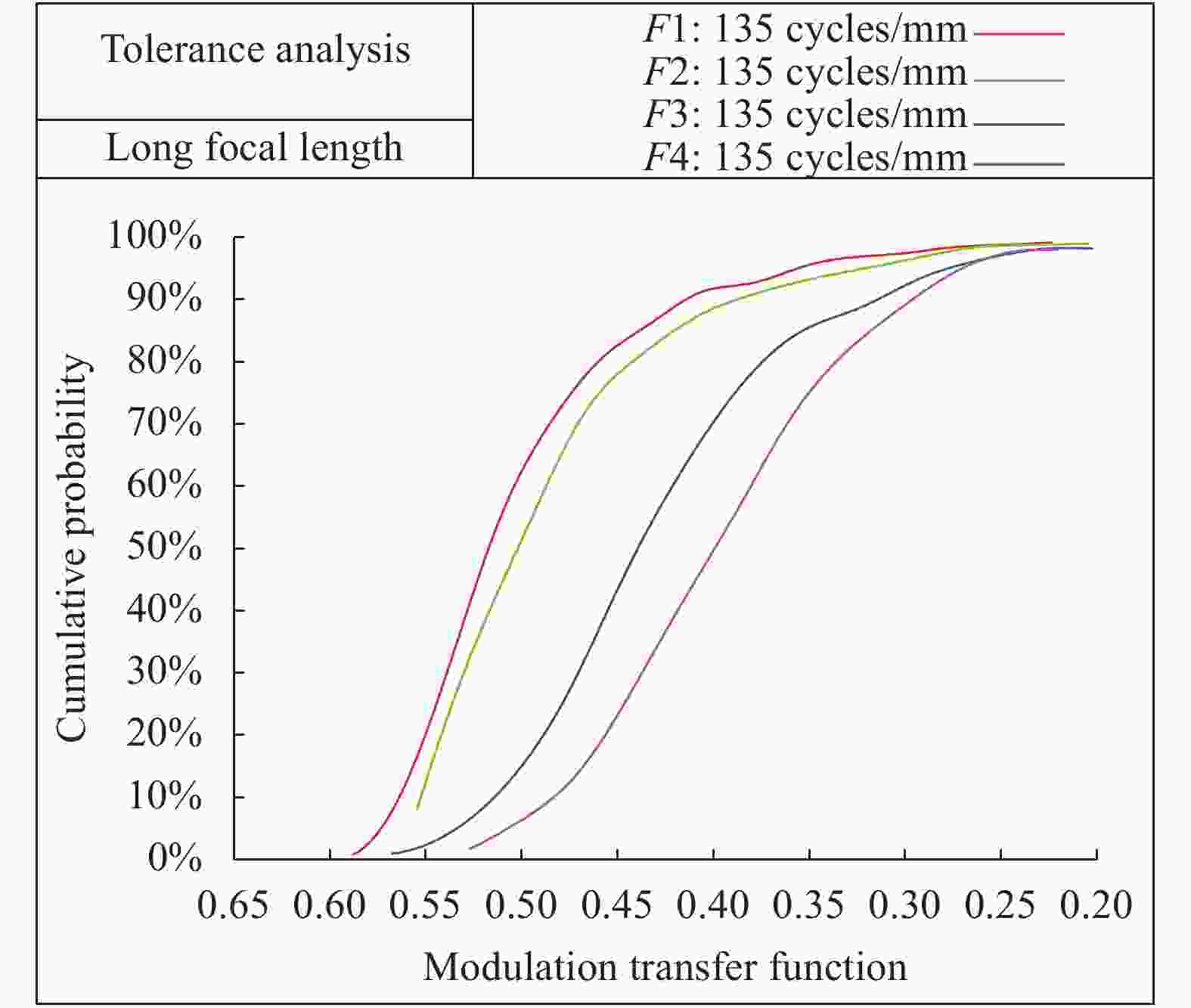
Figure 14. Curves of tolerance analysis at long focal length
-
采用光阑位置切换方案,针对1080P高清相机,考虑低照度环境的正常使用,设计了一套光学总长为150 mm,最大通光孔径为Φ42 mm,变焦行程为35.97 mm,短焦焦距为32 mm,对应F数为2.3,长焦焦距为126 mm,对应F数为3的双视场可见光镜头。与常规的光阑位置固定方案相比,光阑位置切换方案能够实现轴向尺寸12%、最大通光孔径19%、变焦行程43%的有效压缩和相对孔径34%、14%的提升;在特征频率135 cycles/mm处,全视场MTF均在0.45以上,明显优于光阑位置固定方案。公差分析结果表明,在
$135\;{\rm{cycles}}/{\rm{mm}}$ 处,全视场MTF大于0.3的概率达到90%以上。光阑位置切换方案为匹配高清相机、大相对孔径的双视场镜头的紧凑化设计提供了新思路。
Design of compact dual-field lens for visible light
doi: 10.3788/IRLA20210042
- Received Date: 2021-01-04
- Rev Recd Date: 2021-04-14
- Publish Date: 2021-08-25
-
Key words:
- optical design /
- dual-field /
- optical zoom /
- compact
Abstract: To make observing and sighting system realize detecting and recognizing function with simple and compact structure, optical compensation method is selected to design compact dual-field lens working at visible light. Firstly, camera was selected and focal length was calculated according to specifications of filed angle and operating range, F number was calculated according to pixel size and minimal illumination of the selected camera, the characters of dual-field optical system were analyzed. Secondly, conventional fixed stop position scheme and switchable stop position scheme were compared, it was concluded that the latter realized total optical length, maximal effective aperture, zoom stroke compressed and larger relative aperture, better image quality. Finally, compact dual-field lens working at visible light composed of 11 lenses, with total optical length 150 mm, maximal effective aperture Φ42 mm, zoom stroke 35.97 mm was designed by switchable stop position scheme. The lens’s parameters were: short focal length was 32 mm, F number was 2.3, met the requirements that horizontal field angle was larger than 12° and detecting range was farther than 5 km; long focal length was 126 mm, F number was 3, met the requirements that horizontal field angle was larger than 3°, distortion was less than 0.5%, and recognizing range was farther than 5 km. Designing results show that for short focal length 32 mm and long focal length 126 mm, MTF curves of all fields get higher than 0.45, RMS spot diagrams of all fields are less than or close to 4 μm, image quality is good enough. Tolerance analysis showed, at 135 cycles/mm, the probability that MTF curves of all fields were higher than 0.3 was 90% above.


 DownLoad: