Volume 50 Issue 8
Aug.  2021
Turn off MathJax
Article Contents

Geng Jingtong, Yang Liu, Zhao Shuhua, Zhang Yonggang. Recent development of resonant micro cavity in resonant micro-optical gyro[J]. Infrared and Laser Engineering, 2021, 50(8): 20210044. doi: 10.3788/IRLA20210044
Citation: Geng Jingtong, Yang Liu, Zhao Shuhua, Zhang Yonggang. Recent development of resonant micro cavity in resonant micro-optical gyro[J]. Infrared and Laser Engineering, 2021, 50(8): 20210044. doi: 10.3788/IRLA20210044

Recent development of resonant micro cavity in resonant micro-optical gyro

doi: 10.3788/IRLA20210044
  • Received Date: 2020-12-05
  • Rev Recd Date: 2021-02-05
  • Publish Date: 2021-08-25
  • Resonant micro-optical gyros (RMOG) based on Sagnac effect has great potential in integration, miniaturization and sensitivity, which has broad application prospects in the fields of micro nano satellite attitude control, robot control, medical diagnosis and detection instruments, and has become a research hotspot in recent years. Resonant micro cavity as the core sensing element of resonator micro optical gyroscope, the optical characteristics of which are closely related to the performance of gyroscope system. The research progress of resonator has seriously restricted the development of RMOG. At present, integrated optical technology, micro nano optical processing technology and the application of new materials can reduce the weight and size of the resonator, reduce the cost and power consumption, and increase the reliability and performance index of the system. Combined with the information disclosed by periodical conference and related research institutions, the development status, basic principle and characteristic parameters of resonant micro optical gyroscope were briefly introduced. Various new structure designs of resonant micro cavity at home and abroad were listed, and the characteristics and potential of different structures were analyzed. In addition, the new materials for fabrication of resonant micro cavity at home and abroad were reviewed, and the optical properties of different materials were summarized. The future development direction and technical development path of resonator micro cavity for resonator micro optical gyroscope were preliminarily discussed.
  • [1] Santoso F, Garratt M A, Anavatti S G. Visual-inertial navigation systems for aerial robotics: sensor fusion and technology [J]. IEEE Transactions on Automation Science and Engineering, 2017, 14(1): 260-275. doi:  10.1109/TASE.2016.2582752
    [2] Zega V, Comi C, Minotti P, et al. A new MEMS three-axial frequency-modulated (FM) gyroscope: A mechanical perspective [J]. European Journal of Mechanics - A/Solids, 2018, 70: 203-212. doi:  10.1016/j.euromechsol.2018.02.005
    [3] Ren J, Hodaei H, Harari G, et al. Ultrasensitive micro-scale parity-time-symmetric ring laser gyroscope [J]. Optics Letters, 2017, 42(8): 1556-1559. doi:  10.1364/OL.42.001556
    [4] Ma K, Song N, Jin J, et al. Configuration optimization in miniature interferometric fiber-optic gyroscopes for space application [J]. IEEE Sensors Journal, 2020, 20(13): 1-1. doi:  10.1109/JSEN.2020.2991711
    [5] Alexia R, Gilles F, Benoît D, et al. Rotation measurements using a resonant fiber optic gyroscope based on Kagome fiber [J]. Applied Optics, 2019, 58(9): 2198-2204. doi:  10.1364/AO.58.002198
    [6] Shupe D M. Fiber resonator gyroscope: sensitivity and thermal nonreciprocity [J]. Applied Optics, 1981, 20(2): 286-289. doi:  10.1364/AO.20.000286
    [7] Yang S M, Wang X D, Sun M Q, et al. Wavelength switchable and tunable dissipative soliton mode-locking Yb-doped fiber laser [J]. Infrared and Laser Engineering, 2020, 49(10): 20200026. (in Chinese)
    [8] Zu J Q, Wu S, Zhang H T, et al. Yb-doped all-fiber laser based on fiber saturable absorber [J]. Infrared and Laser Engineering, 2020, 49(6): 20190382. (in Chinese)
    [9] Du R N, Chen C, Qin L, et al. Narrow linewidth external cavity semiconductor laser based on silicon photonic chip [J]. Chinese Optics, 2019, 12(2): 20191202. (in Chinese) doi:  10.3788/co.20191202.0229
    [10] Zeng Y J, Zhang J, Xu D H, et al. Fabrication of substrate and film in MEMS using CMP [J]. Optics and Precision Engineering, 2018, 26(6): 1450-1461. (in Chinese) doi:  10.3788/OPE.20182606.1450
    [11] Haavisto J, Pajer G A. Resonance effects in low-loss ring waveguides [J]. Optics Letters, 1980, 5(12): 510-512. doi:  10.1364/OL.5.000510
    [12] Zhang J, Ma H, Li H, et al. Single-polarization fiber-pigtailed high-finesse silica waveguide ring resonator for a resonant micro-optic gyroscope [J]. Optics Letters, 2017, 42(18): 3658-3661. doi:  10.1364/OL.42.003658
    [13] Wu C, Lin Y, Jin X, et al. Synchronous in-phase and quadrature demodulation technique for resonant micro-optic gyroscope [J]. Applied Optics, 2019, 58(18): 5050-5056. doi:  10.1364/AO.58.005050
    [14] Liang W, Ilchenko V S, Savchenkov A A, et al. Resonant microphotonic gyroscope [J]. Optica, 2017, 4(1): 114-117. doi:  10.1364/OPTICA.4.000114
    [15] Liang W, Anatoliy S, Vladimir L, et al. On Sagnac frequency splitting in a solid-state ring Raman laser [J]. Optics Letters, 2017, 42(22): 4736-4739. doi:  10.1364/OL.42.004736
    [16] Ciminelli C, Campanella C E, Dell'Olio F, et al. Theoretical investigation on the scale factor of a triple ring cavity to be used in frequency sensitive resonant gyroscopes [J]. Journal of the European Optical Society Rapid Publications, 2013, 8: 13050. doi:  10.2971/jeos.2013.13050
    [17] Jiao X Q, Yu H B, Yu M, et al. Coupled resonator-induced transparency on a three-ring resonator [J]. Chinese Physics B, 2018, 27(7): 074212. doi:  10.1088/1674-1056/27/7/074212
    [18] Zamani Aghaie K, Digonnet M J F. Effect of periodic modulation of the coupling ratios on the sensitivity of a CROW gyroscope [J]. Journal of the Optical Society of America B, 2015, 32(6): 1120-1124. doi:  10.1364/JOSAB.32.001120
    [19] Ciminelli C, Dell"Olio F, Armenise M N. High-Q spiral resonator for optical gyroscope applications: numerical and experimental investigation [J]. IEEE Photonics Journal, 2012, 4(5): 1844-1854. doi:  10.1109/JPHOT.2012.2218098
    [20] Ciminelli C, D'Agostino D, Carnicella G, et al. A high- InP resonant angular velocity sensor for a monolithically integrated optical gyroscope [J]. IEEE Photonics Journal, 2015, 8(1): 1-19.
    [21] Ma H, Zhang J, Wang L, et al. Resonant micro-optic gyro using a short and high-finesse fiber ring resonator [J]. Optics Letters, 2015, 40(24): 5862-5865. doi:  10.1364/OL.40.005862
    [22] Qian G, Fu X C, Zhang L J, et al. Hybrid fiber resonator employing LRSPP waveguide coupler for gyroscope [J]. Scientific Reports, 2017, 7: 41146. doi:  10.1038/srep41146
    [23] Li J, Suh M G, Vahala K. Microresonator Brillouin gyroscope [J]. Optica, 2017, 4(3): 346. doi:  10.1364/OPTICA.4.000346
    [24] Qian G, Tang J, Zhang X Y, et al. Low-loss polymer-based ring resonator for resonant integrated optical gyroscopes [J]. Journal of Nanomaterials, 2014(3): 1-6.
    [25] Qian G, Zhang T, Zhang L J, et al. Demonstrations of centimeter-scale polymer resonator for resonant integrated optical gyroscope [J]. Sensors and Actuators A: Physical, 2016, 237: 29-34. doi:  10.1016/j.sna.2015.10.049
    [26] Bauters J F, Heck M J R, John D D, et al. Planar waveguides with less than 0.1 dB/m propagation loss fabricated with wafer bonding [J]. Optics Express, 2011, 19(24): 24090-24101. doi:  10.1364/OE.19.024090
    [27] Tien M C, Bauters J F, Heck M J R, et al. Ultra-high quality factor planar Si3N4 ring resonators on Si substrates [J]. Optics Express, 2011, 19(14): 13551-13556. doi:  10.1364/OE.19.013551
    [28] Spencer D T, Bauters J F, Heck M J R, et al. Integrated waveguide coupled Si3N4 resonators in the ultrahigh-Q regime [J]. Optica, 2014, 1(3): 153-157. doi:  10.1364/OPTICA.1.000153
    [29] Savchenkov A A, Andrey B M, Vladimir S Ilchenko, et al. Optical resonators with ten million finesse [J]. Optics Express, 2007, 15(11): 6768-6768. doi:  10.1364/OE.15.006768
    [30] Matsko A B, Liang W, Anatoliy A S, et al. Fundamental limitations of sensitivity of whispering gallery mode gyroscopes [J]. Physics Letters A, 2017, 382(33): 2289-2295.
    [31] Niehusmann J, Vrckel A, Bolivar P H, et al. Ultrahigh-quality-factor silicon-on-insulator microring resonator [J]. Optics Letters, 2004, 29(24): 2861-2864. doi:  10.1364/OL.29.002861
    [32] Biberman A, Timurdogan E, Wright J B, et al. Ultralow-loss silicon ring resonators[C]//IEEE International Conference on Group IV Photonics, 2012, 37(20): 4236-4238.
  • 加载中
通讯作者: 陈斌, bchen63@163.com
  • 1. 

    沈阳化工大学材料科学与工程学院 沈阳 110142

  1. 本站搜索
  2. 百度学术搜索
  3. 万方数据库搜索
  4. CNKI搜索

Figures(8)  / Tables(2)

Article Metrics

Article views(644) PDF downloads(115) Cited by()

Related
Proportional views

Recent development of resonant micro cavity in resonant micro-optical gyro

doi: 10.3788/IRLA20210044
  • College of Intelligent Systems Science and Engineering, Harbin Engineering University, Harbin 150001, China

Abstract: Resonant micro-optical gyros (RMOG) based on Sagnac effect has great potential in integration, miniaturization and sensitivity, which has broad application prospects in the fields of micro nano satellite attitude control, robot control, medical diagnosis and detection instruments, and has become a research hotspot in recent years. Resonant micro cavity as the core sensing element of resonator micro optical gyroscope, the optical characteristics of which are closely related to the performance of gyroscope system. The research progress of resonator has seriously restricted the development of RMOG. At present, integrated optical technology, micro nano optical processing technology and the application of new materials can reduce the weight and size of the resonator, reduce the cost and power consumption, and increase the reliability and performance index of the system. Combined with the information disclosed by periodical conference and related research institutions, the development status, basic principle and characteristic parameters of resonant micro optical gyroscope were briefly introduced. Various new structure designs of resonant micro cavity at home and abroad were listed, and the characteristics and potential of different structures were analyzed. In addition, the new materials for fabrication of resonant micro cavity at home and abroad were reviewed, and the optical properties of different materials were summarized. The future development direction and technical development path of resonator micro cavity for resonator micro optical gyroscope were preliminarily discussed.

  • 在广泛应用的导航系统中,惯性导航系统具有完全自主和高度隐蔽等特性,其在国防军事上尤其是姿态控制系统和惯性导航系统中拥有异乎寻常的重要性。陀螺仪是惯性导航系统的重要组成部分[1],其中包括机械陀螺仪[2]、激光陀螺仪[3]、干涉式光纤陀螺仪[4]和谐振式光学陀螺仪[5]等。环形激光陀螺内部光电部件繁多且体积较大。干涉式光纤陀螺具有高精度等优点,但是其主要依赖于几公里的光纤环,不利于器件的小型化与大批量生产。目前,谐振式微光学陀螺(RMOG)处于基础研究阶段,但因其在集成化、抗振动冲击以及高灵敏度等方面的优势,而具有较大的研究价值与应用潜力[6]。同时,随着微半导体加工技术的快速发展[7-8],以及科技产业对微型化、集成化的迫切需求,RMOG成为了重要技术研究发展方向。

    RMOG具有以下优点:(1)理论灵敏度高。随着微纳加工技术的发展,各种低损耗、高分辨率的谐振微腔已研制成功,有效提高了理论灵敏度。(2)小型化和集成化的潜力。近年来,硅基混合集成光电子集成电路越来越受到人们的重视,RMOG中的每一个光学元件都可以通过集成的光学微加工工艺来实现[9-10]。(3)避免闭锁效应。RMOG中的谐振腔中也存在着后向散射噪声,但基本可以通过双频载波抑制方法消除以避免闭锁效应。接下来,文中将具体介绍谐振腔的结构设计和制作材料,同时对RMOG技术领域的发展进行分析和展望。

    • 谐振微腔是RMOG的核心敏感单元,可以从Q值、集成度和微型化等方面来评判其性能。1980年,美国研究人员第一次提出光波导谐振腔的概念并首次制造出环形结构的谐振腔(清晰度16、传输损耗0.05 dB/cm)[11],人们也开始从微腔的基础理论研究逐渐转移至实际应用,目前主流的谐振微腔包括波导环形谐振腔、回音壁模式谐振腔、混合谐振腔等,下面将一一进行介绍。

    • 20世纪90年代,Northrop公司报道了谐振式微光学陀螺的样机,随后基于波导环形谐振腔的RMOG进入高速发展时期。2018年,浙江大学研究人员在硅基二氧化硅环形光波导上研制出直径为2.5 cm、腔长为7.9 cm的谐振腔,为了减少波导直、弯段之间的模态转换损失而将谐振腔设计为跑道结构。测试结果显示清晰度和谐振深度分别达到196.7和 98%[12]。2019年,为了克服系统相位波动的影响,该团队引入了同相和正交(IQ)解调技术,随机游走系数和长期偏置稳定性分别达到了0.5 (°)·h−1/2和9 (°)/h[13]。2019年,俄罗斯联邦圣彼得堡国立大学提出了基于光波导环形谐振腔的谐振微光学陀螺新方案。如图1所示,这种方法使用马赫-曾德尔波导干涉仪(MZI)代替可调谐激光器进行扫频,该MZI的两臂上分别与环形波导谐振腔和相位调制器相连接,角速度通过MZI输出端功率的最大值和最小值之间的差值决定。该方案简化了结构并且增加了集成度。但不足之处是量程有限,文中也讨论了克服该局限的方法。

      Figure 1.  Resonator structure based on MZI

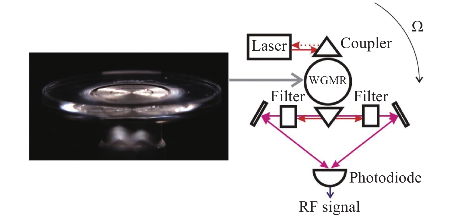
    • 回音壁模式(WGM)光学微腔具有极高的品质因子,能极大地增强腔内光场与物质的相互作用,已经成为超高灵敏光学传感的优异平台和前沿研究热点。2016年,OEwaves公司制造了一个直径和高度分别为1 cm 和0.2 mm的超高Q值光学回音壁模式谐振腔,Q值达到了1010,这项研究证明了基于回音壁模式谐振腔的光学陀螺在集成化、微型化和灵敏度等方面具备的可行性。2017年,该公司又进一步抑制了偏振波动噪声和瑞利背向散射,实验最终获得了3 (°)/h的零偏稳定性,对应于检测旋转产生的光程变化仅为1.3×10−16 cm[14]。2017年,Liang Wei等人利用自注入锁定对回音壁模式微腔的Sagnac效应进行了实验,如图2所示,主要原理是根据谐振腔的瑞利散射效应将激光器的输出频率锁定在谐振腔的谐振频率上,当泵浦光的功率超过某个阈值时会激发拉曼激光,最后使用频率计测量拍频信号,结果显示测量精度为1 (°)/s。虽然此方案目前存在不足,但是为我们提供了一个新的研究角度[15]

      Figure 2.  Experimental device diagram

    • 近十年来,基于新型多环结构的角速度传感器引起了研究人员的注意,该结构被称为耦合谐振腔光波导(CROW)。CROW是一种用于操纵光脉冲群速度以获得慢光信号的光学结构,目的是为了增强Sagnac效应。2013年,意大利巴里理工学院提出了基于三个渐逝耦合环形谐振腔的微光学陀螺仪,如图3所示,这种三环谐振腔相对于单环谐振腔的优势是,若实现陀螺相同的标度因数,三环谐振腔的敏感环面积可以减少约两倍[16]。2015年,焦新泉等人制备了基于耦合诱导透明(CRIT)效应的三环谐振微腔[17],其原理是利用谐振腔之间的相干干涉,结果显示谐振曲线具有较窄的谐振峰和较低的群速度, 并且谐振腔的品质因数达到了0.65×10⁵。同年,斯坦福大学研究团队从理论上分析了基于CROW的微光学陀螺和耦合率相同的单谐振腔的RMOG理论灵敏度,分析表明CROW微光学陀螺略优于传统的单谐振腔的RMOG[18]

      Figure 3.  Three ring CROW resonator

    • 研究人员借鉴RFOG中光纤的环形结构,采用了低损耗螺线圈形式的光波导环以提升陀螺仪的灵敏度。2012年,意大利巴里理工大学采用三环螺旋结构的集成光学谐振腔,实验结果显示Q值超过106[19]。2015年,该课题组与荷兰COBRA研究中心合作研究多模干涉耦合器耦合到直母线波导的螺旋谐振腔,如图4所示。该谐振腔使用标准传递矩阵方法进行设计,所选择的制造工艺是标准COBRA工艺的增强版本,允许将传感元件与陀螺仪的其他有源部件单片集成,实验结果显示,测试Q值约为6×10⁵,理论分辨率为150 (°)/h[20]

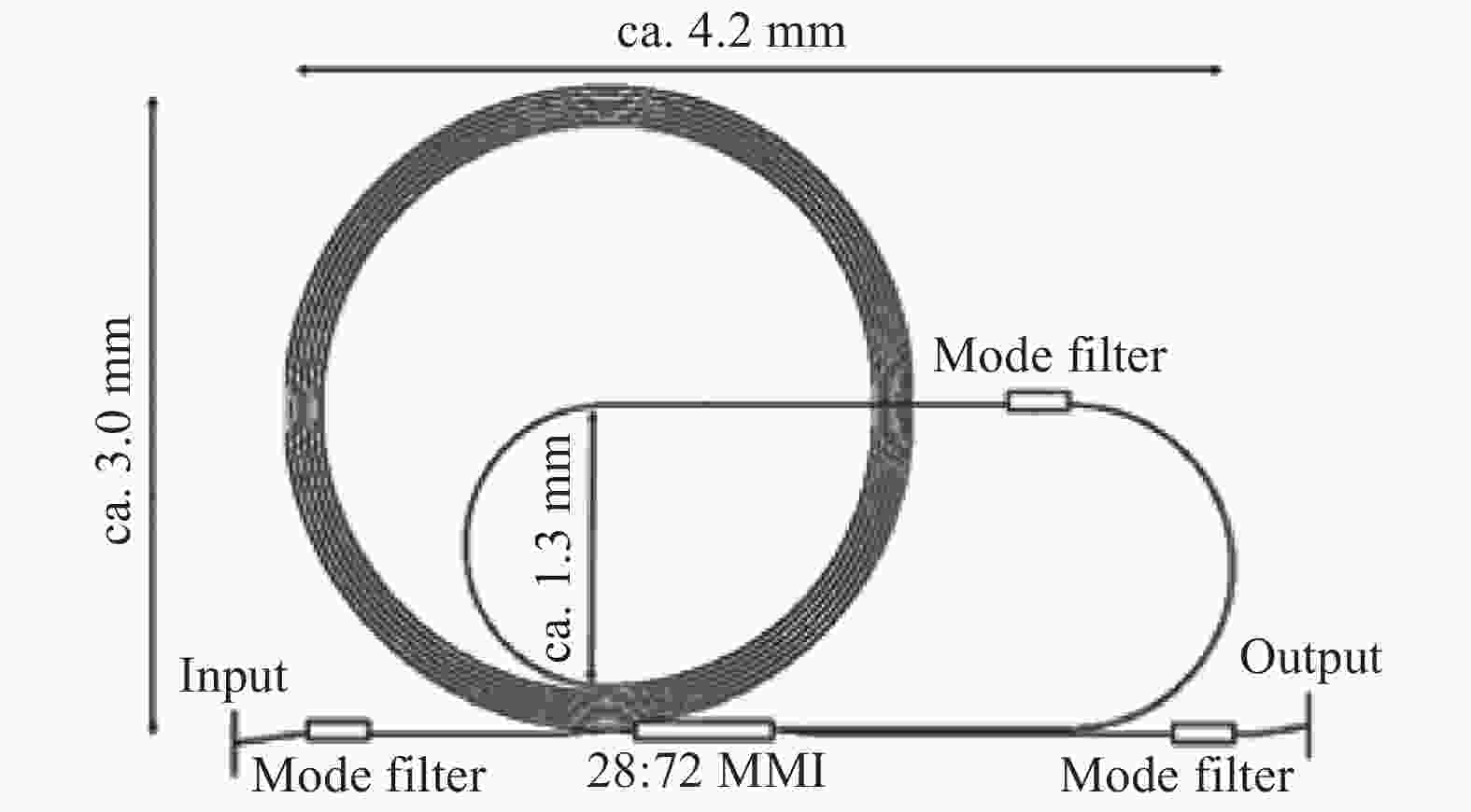
      Figure 4.  Spiral resonator based on InP substrate

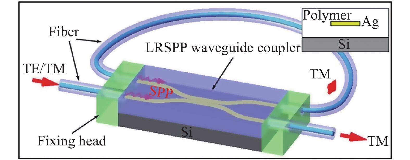
    • 为了减少平面型波导谐振腔有效面积受到晶圆面积的限制以及偏振噪声和温度噪声的影响,研究人员通过使用光纤与基底固定的方式来减少损耗。2015年,浙江大学研究团队在硅基底上刻蚀出 V 形光纤掩埋槽,制造了长度为60 cm,直径为4.77 cm,清晰度达到202的短环形谐振器腔,其他光学元件都集成在单个硅片上,成功实现了小型化的封装。测试结果显示,角度随机游动系数为0.64 (°)·h−1/2,50 s积分时间下的陀螺零漂稳定性达到9.6 (°)/h,证明了该谐振腔可以适用于战术级RMOG[21]。2017年,东南大学研究小组制作了一种由1.5 cm长的基于聚合物的等离子体激元波导耦合器和30 cm长的二氧化硅光纤组成的混合谐振腔,如图5所示。该混合谐振腔可以有效地抑制由次偏振态引入的偏振噪声,并大大提高陀螺仪系统的温度稳定性。经过理论计算,在1 s积分时间和10 mW的探测功率下,预计陀螺理论灵敏度为4.5 (°)/h,短光纤混合集成谐振腔为战术级RMOG提供了一种实现途径[22]

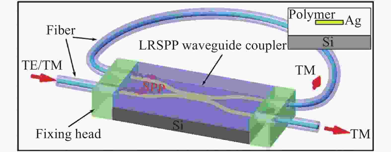
      Figure 5.  Hybrid resonator based on waveguide coupler and fiber

      综上所述,经过一段时期的发展,基于波导环形谐振腔的光学陀螺已经逐渐接近于导航级需求,但是距离军事应用还有一定距离。回音壁模式谐振腔具有极大的Q值,但同时也有成本高和光路对准误差等劣势,随着微纳加工技术的进步,有望逐步解决种种技术挑战。此外,基于多环耦合的微光学陀螺发展遇到了瓶颈,为了获得低损耗和高Q值的谐振腔,需要极为苛刻的制作工艺。螺线圈形式谐振腔已经得到了很好的应用,随着设计结构的进一步完善和新型低损耗材料的出现,其仍有很大的发展空间。最后,短光纤混合谐振腔在抑制噪声和降低损耗方面是一种十分有效的解决方案,但是仍存在精度不足的问题。根据目前谐振腔的研究情况,列出了不同谐振腔的结构特点,如表1所示。

      Resonator typeIntegration difficultySize
      Monolithic optical waveguide ring resonator[12]EasyCentimeter
      Echo Wall mode resonator[14]EasyMicron
      Multi ring optical waveguide ring resonator[16]EasyCentimeter
      Spiral coil resonator[20]ModerateMillimeter
      Short fiber hybrid integrated resonator[21]ModerateCentimeter

      Table 1.  Structural characteristics of resonators

    • 谐振微腔作为RMOG的关键组成部分,其制作材料直接影响着RMOG的精度。SiO2材料应用广泛,主要优点是吸收损耗小,适合制作无源波导器件;基于绝缘底上硅SOI的硅基光子集成技术适合研制低损耗、高精细度的谐振腔;聚合物材料由于具备电光调制性能,在调制器与谐振腔集成的方案中具有一定优势;CaF2因其较好的光学性能、化学稳定性和机械特性在制作超高Q值谐振腔的材料中具有明显优势;Si3N4材料具有非常优良的低损耗特性。下面将对上述几种不同材料的谐振微腔进行简要介绍。

    • SiO2光波导作为谐振式集成光学陀螺仪最早可实现方式的一种,一直被国内外研究机构所重视,该材料具有更低的传输损耗,实现具有较高清晰度的谐振腔。2013年,意大利C. Ciminelli等人提出了一种用于提升SiO2环形谐振腔Q值的方法,该谐振腔直径为4.59 cm,其路径包括一个低折射率布拉格光栅,该光栅在其整个长度上延伸,并通过UV将其刻蚀在腔内(如图6所示),假设波导在0.07 dB/cm的传输损耗的条件下,这种谐振腔的Q值可达7×l09。2017年,美国加州理工大学利用直径仅为18 mm的SiO2碟形波导研制出谐振式布里渊陀螺实验样机,其原理是基于不同阶次的斯托克斯激光信号在 Sagnac效应影响下产生的差异来测量角速度,实验结果显示该陀螺仪具有15 (°)·h−1Hz−1/2的灵敏度,测量的最小旋转速率为22 (°)/h[23]

      Figure 6.  Silicon based SiO2 ring resonator with grating

    • 聚合物的发展速度及应用的广泛性大大超过了传统材料,目前聚合物材料正朝着功能化、智能化、精细化的方向发展,基于聚合物的集成光学器件已在许多实验室中广泛使用。2014年,东南大学研制了一种用于谐振集成光学陀螺仪的大直径、低传输损耗的聚合物谐振腔,如图7所示,从横截面可以看出该结构是将一个聚合物条埋在另一个聚合物中,并且包层和埋芯的折射率对比度为0.01。通过对谐振腔分析和测量,聚合物波导在1550 nm的入射波长下测得的传播损耗约为0.476 dB/cm,理论散粒噪声限制灵敏度小于20 (°)/h[24]。2016年,东南大学使用基于丙烯酸脂的紫外光固化含氟树脂制作了谐振腔,最终制作出Q值为1×105,光传播损耗为0.5 dB/cm的谐振腔,在散粒噪声限制下,陀螺理论灵敏度小于0.09 (°)/s[25]

      Figure 7.  Polymer resonator structure

    • 氮化硅是一种典型的耐高温原子晶体,具有很高的化学惰性和高温强度,主要应用于结构陶瓷、高温结构材料和耐热涂层等领域。2011年,美国加州大学提出了一种芯层为Si3N4,包层为 SiO2的高Q值光波导,其主要优势是通过热氧化法制成的氧化物上下包层可以减少部分损耗,而且由于热氧化物的生长和波导处理可以同时进行,因此带粘接的热氧化物包层的波导具有更短的制造时间,实验测得总传输损耗为(0.045±0.04)dB/m[26]。同年,该课题组在Si衬底研制出了具有2.8×108的超高Q值的超低损耗Si3N4环形谐振腔[27]。2014年,该课题组又提出了基于超低损耗Si3N4波导平台的集成谐振腔。通过使用谐振腔定向耦合器,能够实现比直线总线波导定向耦合器更低损耗的耦合,如图8所示,为了解决损耗大、低Q值的问题,谐振腔采用了“弱锥形间隙”定向耦合器。实验结果测得其Q值达到了8.1×108[28]

      Figure 8.  Cross section of the waveguide

    • CaF2晶体是一种透光波段为0.13~10 µm的光学晶体材料,具有良好的透光性和较低的折射率,是制作紫外和红外光学仪器的元件。美国宇航局喷气动力实验室在2007年利用CaF2晶体经过三次迭代退火步骤加工了回音壁模式光学谐振腔,最终制备了直径为1.55 μm,精细度和Q值分别为107和1011的WGM谐振腔,证明了CaF2材料经过适当的热退火步骤与机械抛光相结合的方式可以制造出具有极大品质因数的WGM谐振腔[29]。2017 年,OEwave公司采用7 mm直径的CaF2谐振腔研制出精细度为105的谐振式光学陀螺仪,对应于检测到最小光路变化为1.3×10⁻¹⁶ cm。2018年,Andrey B. Matsko等研究人员通过研究表明CaF2谐振腔主体材料中的光学非线性会导致量子反作用噪声,而将谐振腔的尺寸增加到厘米量级可以大大提升灵敏度,并通过实验证明了直径大小为1 mm的微陀螺仪角度随机游走极限为0.2 (°)·h−1/2[30]

    • SOI是在顶层硅和背衬底之间引入了一层埋氧化层, 将光限制在顶层单晶硅中传播。2004年Jan Niehusmann等人制备了基于SOI的微环谐振腔,通过HBr感应耦合反应离子刻蚀实现模式转换,选择性地停留在Si/SiO2界面,通过优化刻蚀参数,使表面粗糙度最小化,其传输损耗为(1.9±0.1) dB/cm,Q值达到了1.4×105[31]。2012年,美国Biberman等人设计并制作了Q值为2.2×107的SOI光波导谐振腔,该SOI光波导损耗低至0.027 dB/cm,测试结果显示该谐振腔半高全宽和自由谱宽分别为9.9 MHz和5.35 GHz,其脊形波导结构大大减少了侧壁与TE和TM模式的相互作用[32]

      综上所述,随着未来制作工艺和技术的不断提升,硅基SiO2光波导将继续拥有很大潜力。此外,聚合物材料需要进一步解决热稳定性差和长期稳定性差等问题。Si3N4材料已经成功用于谐振微腔的制备并取得了一定成果,但还没有将其应用于光学陀螺实验结果的公开报道。CaF2材料具有特别优秀的光学性能、化学稳定性和力学性能,在未来微型光学陀螺的发展中将具有重要的应用价值。Smart Cut材料则是非常有发展前景的SOI材料,它很有可能成为今后SOI材料的主流。表2为不同材料的性能参数。

      MaterialsTransmission loss/ dB·cm−1Q
      SiO2[23]10−2 109
      Polymer[25]10−2 105
      Si3N4[27]10−4 108
      CaF2[29]10−4 1011
      SOI[32]10−2107

      Table 2.  Performance parameters of materials

    • 文中从谐振腔结构设计和材料选用方面回顾了近几年来谐振式集成光学陀螺的研究情况,其目的在于顺应国家重大工程需求,紧跟惯性陀螺仪微型化、集成化形势,跟踪了解新结构、新材料的应用状况,为最终实现微型化可集成的谐振式光学陀螺寻找切实可行的解决方案。未来谐振式陀螺将朝着微体积、低功耗、高可靠性、低成本和抗振动冲击等特点继续发展,今后一段时间的研究重心可能将集中在以下几个方面:提升制备工艺以及材料的纯度来进一步提高微谐振腔的Q值;进一步减少光波导损耗,提高谐振腔清晰度;继续深化发展硅基混合集成光电子技术,使之成为最有潜力的集成光学陀螺制造平台。

Reference (32)

Catalog

    /

    DownLoad:  Full-Size Img  PowerPoint
    Return
    Return