


HTML
-
跨极区长航时飞行要求飞行器具备全球导航能力,并且较大的飞行动态性与复杂的极区环境对导航过程的连续性和稳定性提出了更高的要求。在中低纬度地区,航空飞行器通常以当地水平地理坐标系作为导航坐标系,并将经线作为航向参考[1]。然而随着纬度升高,经线在两极地区高度汇聚,经线基准无法提供有效的航向参考信息[2]。为了解决高纬度地区无有效航向参考基准的问题,需要在极区采用其他航向参考,对极区的导航坐标系进行重新定义,如在极区采用游移方位坐标系[3]、地球坐标系(ECEF坐标系)[4]、横坐标系[5]、格网坐标系[6]等。
目前关于极区组合导航的研究主要关注的是极区范围内的组合导航算法设计[7-10],对组合导航系统如何实现跨极区导航研究较少。同时,跨极区导航存在导航坐标系的转换,需要研究导航坐标系变换情况下的组合导航滤波器设计问题。参考文献[11]基于“当地水平地理坐标系+格网坐标系”设计了跨极区飞行场景下的惯性/天文组合导航算法,但由于忽视了导航坐标系转换带来的滤波器结构变化,出现了滤波器状态参数的振荡、不稳定,影响了导航精度。为了解决惯导编排的全球一致性问题,参考文献[12]在伪地球坐标系设计了惯性导航方案,可以实现大范围、长航时导航,但坐标系切换时的一致性问题依然没有得到根本性解决。参考文献[13]结合了虚拟圆球模型与法向量惯性导航算法在全球范围内实现了惯导编排,然而该编排方案改变了目前机载惯导的导航框架,不利于现有系统升级。
为解决航空飞行器跨极区飞行过程中导航坐标系转换导致的滤波不稳定问题,实现系统误差状态的平滑过渡,文中以机载环形激光陀螺惯导/全球导航卫星系统(Ring Laser Gyroscope Inertial Navigation Sys-tem/Global Navigation Satellite System, RLG INS/GNSS)组合导航系统为例,提出了基于协方差变换的极区组合导航算法。以地理坐标系、格网坐标系下的组合导航滤波器为基础,推导建立了系统误差状态及其协方差矩阵在两个导航坐标系之间的转换关系,设计了滤波状态稳定的组合导航滤波器,解决了坐标系转换过程中的滤波状态跳变问题,满足了航空飞行器的跨极区飞行需求。
-
格网角的定义如图1所示。格网平面平行于格林尼治子午面,其与飞行器位置点处切平面的交线为格网北向。地理北向与格网北向的夹角为格网角,以顺时针为正。格网天向与当地地理坐标系天向相同,其与格网东向、北向一起构成右手直角坐标系。
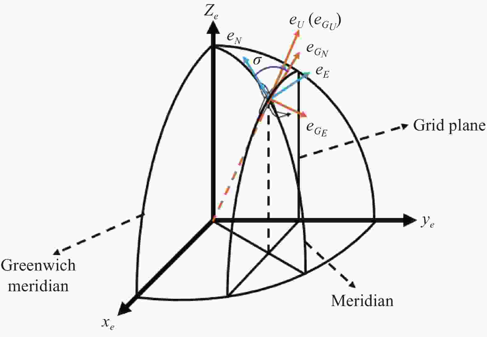
Figure 1. Grid coordinate
其中,格网角
$\sigma $ 的值为[6]:格网系G与地球坐标系e之间的方向余弦矩阵
${\boldsymbol{C}}_e^G$ 定义为[14]:式中:n为当地水平地理坐标系。
格网坐标系下的姿态、速度、位置更新方程与当地水平地理坐标系下的惯导算法编排类似。其中,位置更新借鉴了机载游移方位惯导位置矩阵更新的方式,采用位置矩阵
${\boldsymbol{C}}_e^G$ 对格网坐标系下航空飞行器的位置进行更新:其中,
式中:
${R_x}$ 为格网东向的曲率半径;${R_y}$ 为格网北向的曲率半径;${\tau _f}$ 为扭曲半径。鉴于经线在极区高度汇聚,航空飞行器极区位置信息通常使用ECEF坐标系下的矢径直角坐标(x、y、z)表示,其与经纬高的关系为:
式中:
${R_N}$ 为卯酉圈曲率半径;$f$ 为椭圆扁率。将矢径直角坐标(x、y、z)用${\boldsymbol{C}}_e^G$ 的相关元素表示为:式中:
${c_{ij}}$ 为${\boldsymbol{C}}_e^G$ 中第i行j列元素;$R$ 为地球长半轴长度。基于“位置矩阵+高度”的更新方式,根据公式(7)、(8),既可以获得ECEF坐标系下直角坐标x、y、z,也能获得纬度、经度、高度。 -
格网坐标系下的姿态误差方程、速度误差方程分别为[15]:
姿态误差方程
速度误差方程
位置矩阵误差方程采用位置误差角的微分方程,表示为[9]:
高度误差方程为:
-
航空飞行器跨极区飞行时,存在进入、离开极区的过程,需要完成导航参数在当地水平地理坐标系与格网坐标系之间的转换,以实现惯导编排在中低纬度与高纬度地区之间的切换。其中,导航参数包括姿态参数、速度参数、位置参数。
(1)姿态转换
根据飞行器的姿态矩阵,以及当地水平地理坐标系与格网坐标系间的坐标转换矩阵能够完成进入、离开极区过程中的姿态转换。
(2)速度转换
${{\boldsymbol{v}}^G}$ 的初值根据飞行器进入极区时当地水平地理坐标系下的速度${{\boldsymbol{v}}^n}$ ,由坐标转换矩阵${\boldsymbol{C}}_n^G$ 转换得到。类似地,可以得到飞行器离开极区时${{\boldsymbol{v}}^n}$ 与${{\boldsymbol{v}}^G}$ 的转换关系。(3)位置转换
飞行器进入、离开极区时,位置矩阵
${\boldsymbol{C}}_e^G$ 与经纬度的转换关系可由公式(2)确定。 -
飞行器在进入、离开极区过程中,由于导航坐标系的改变,RLG INS/GNSS组合导航滤波器结构也发生了变化。中低纬度下的组合导航滤波器在地理坐标系下设计,进入极区后变为格网坐标系。因此,组合导航滤波器的系统误差状态、协方差矩阵、状态方程及观测方程均需要完成转换。由于状态方程和观测方程在系统误差状态确定后即可事先确定,与飞行状态无关,因此,只需要完成系统误差状态及协方差矩阵的转换即可。
中低纬度下的系统状态包括三个姿态误差、三个速度误差、三个位置误差、三个陀螺与加表零偏:
相比于地理坐标系下的位置误差
$\delta L$ 、$\delta \lambda $ 、$\delta h$ ,格网坐标系的位置误差表示为${{\boldsymbol{\theta}} ^G}$ 、$\delta h$ ,为了避免RLG INS/GNSS组合导航滤波器在导航坐标系转换前后出现维数不一致的问题,只使用${{\boldsymbol{\theta}} ^G}$ 中的两个分量。下面证明${{\boldsymbol{\theta}} ^G}$ 可以用其中两个分量完全表示。位置矩阵
$\tilde {\boldsymbol{C}}_e^G$ 可以表示为:由公式(16)可得:
式中:
${{\boldsymbol{\theta}} ^G}$ 表示位置误差角。将公式(2)代入公式(17),整理可得:
其中,
将相关量用
${\boldsymbol{C}}_e^G$ 的元素代替,有:根据公式(20),
${{\theta}} _U^G$ 可由${{\theta}} _E^G$ 、${{\theta}} _N^G$ 线性表示,因此,在组合导航滤波器设计过程中只需考虑${{\theta}} _E^G$ 与${{\theta}} _N^G$ 即可完全确定${{\boldsymbol{\theta}} ^G}$ ,这样即能保证组合导航滤波器的维数在导航坐标系转换前后保持一致。综上所述,当航空飞行器处于极区时,组合导航滤波器的系统误差状态为:
对比公式(15)、(21)可以发现,导航坐标系转换前后保持不变的系统误差状态有:体坐标系下表示的陀螺、加速度计常值零偏
${{\bf{\varepsilon}} ^b}$ 、${\nabla ^b}$ ,高度通道误差$\delta h$ 。因此,只需建立姿态误差、速度误差和位置误差之间的转换关系。姿态误差
${\boldsymbol{\phi}} _{}^n$ 与${\boldsymbol{\phi}} _{}^G$ 之间的转换关系确定如下。根据
$\delta {\boldsymbol{C}}_b^G$ 的定义得到:同时,对
${\boldsymbol{C}}_b^G = {\boldsymbol{C}}_n^G{\boldsymbol{C}}_b^n$ 两侧做扰动,得到:其中,
${\boldsymbol{\phi}} _{nG}^G$ 为${\boldsymbol{C}}_n^G$ 的误差角向量,定义为:且有
其中,
综合公式(22)~(24),可以得到:
整理得:
速度误差
$\delta {\boldsymbol{v}}_{}^n$ 与$\delta {\boldsymbol{v}}_{}^G$ 之间的转换关系确定如下:由公式(18)整理可得位置误差(
$\delta L$ 、$\delta \lambda $ )与(${{\theta}} _E^G$ 、${{\theta}} _N^G$ )之间的转换关系:至此可以确定系统误差状态
${{\boldsymbol{x}}^n}(t)$ 与${{\boldsymbol{x}}^G}(t)$ 之间的转换关系如下:式中:
${\boldsymbol{\varPhi}} $ 中的元素可由公式(28)~(30)得到。根据公式(30),可以确定组合导航滤波器中系统误差状态的协方差矩阵转换关系为:
类似地,
至此,设计基于协方差变换的INS/GNSS组合导航滤波器如图2所示。
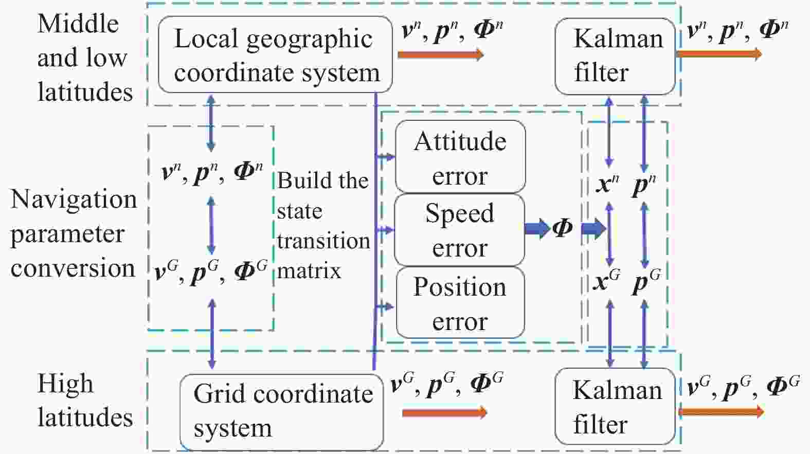
Figure 2. Conversion diagram
-
利用高精度激光陀螺惯导系统共进行了六组跑车实验,其中激光陀螺零偏稳定性优于0.01 (°)/h,加速度计零偏稳定性优于20 μg。跑车起始位置为北纬28.288 7 °,东经112.956 3 °,前1 000 s进行静止对准,3 000 s时切换到格网坐标系,5 000 s时再次转换到地理坐标系,通过坐标系的转换模拟飞行器飞入、离开极区,整个跑车时长约为6 900 s。
鉴于跑车实验是在低纬度进行的,可将整个测试时间内当地水平地理坐标系下的RLG INS/GNSS组合导航结果作为参考基准,分别将基于协方差变换的组合导航结果及无协方差变换的组合导航结果折算到当地水平地理坐标系下进行比较,第一组的结果如图3~图6所示。
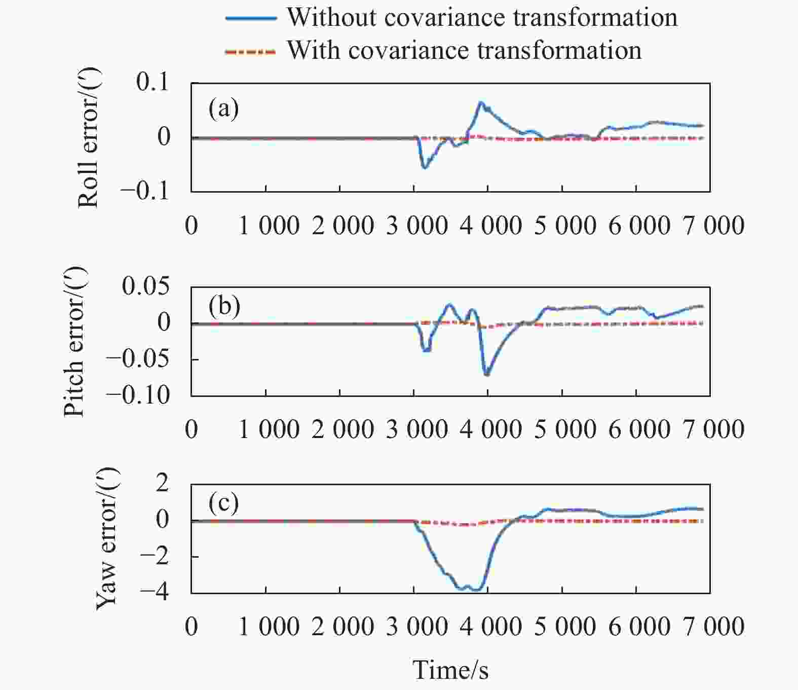
Figure 3. Relative attitude error
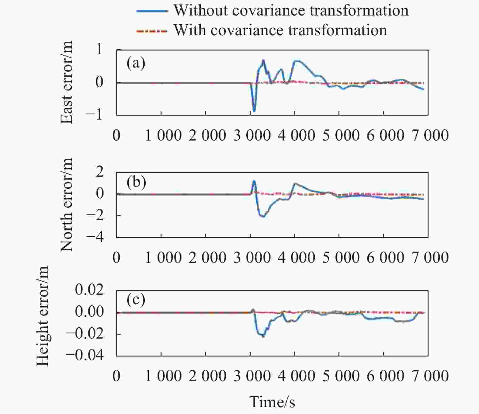
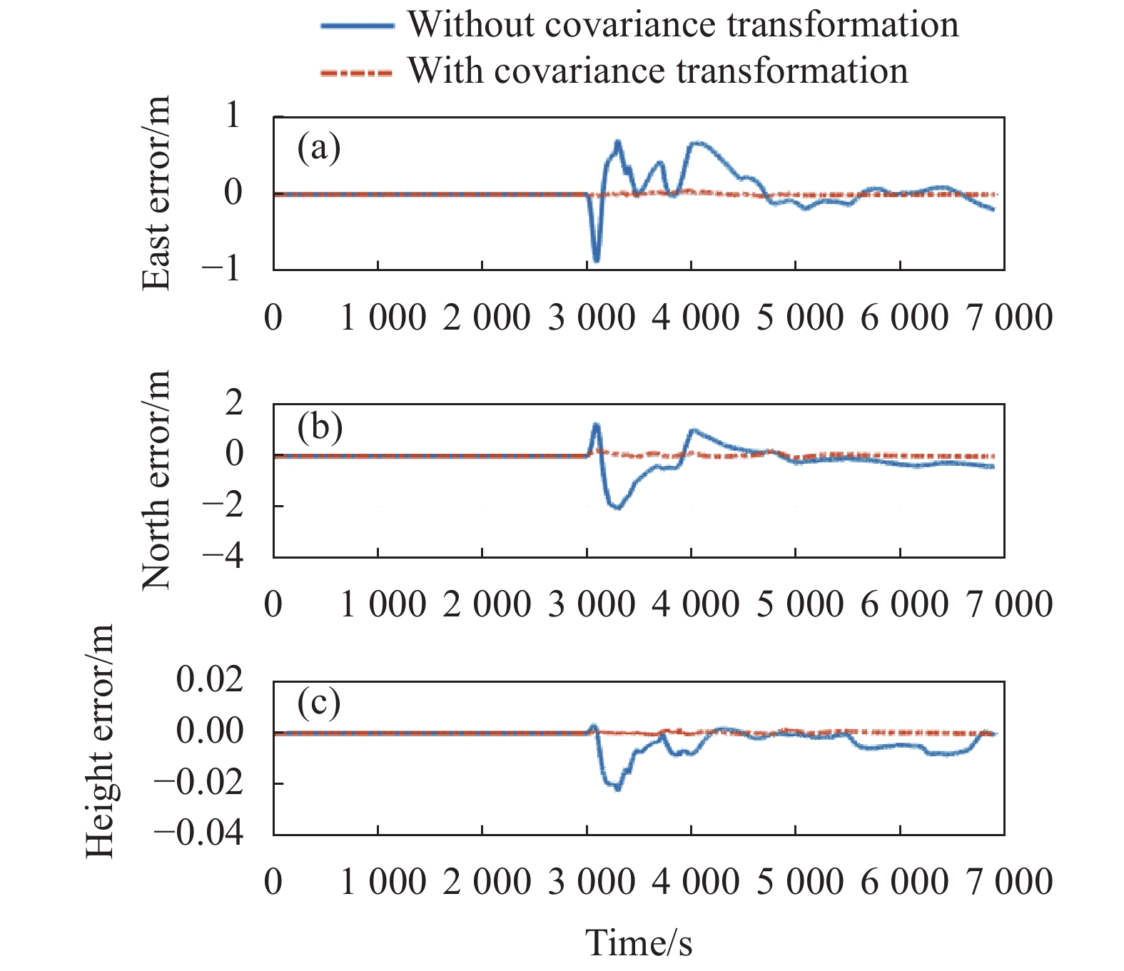
Figure 4. Relative position error
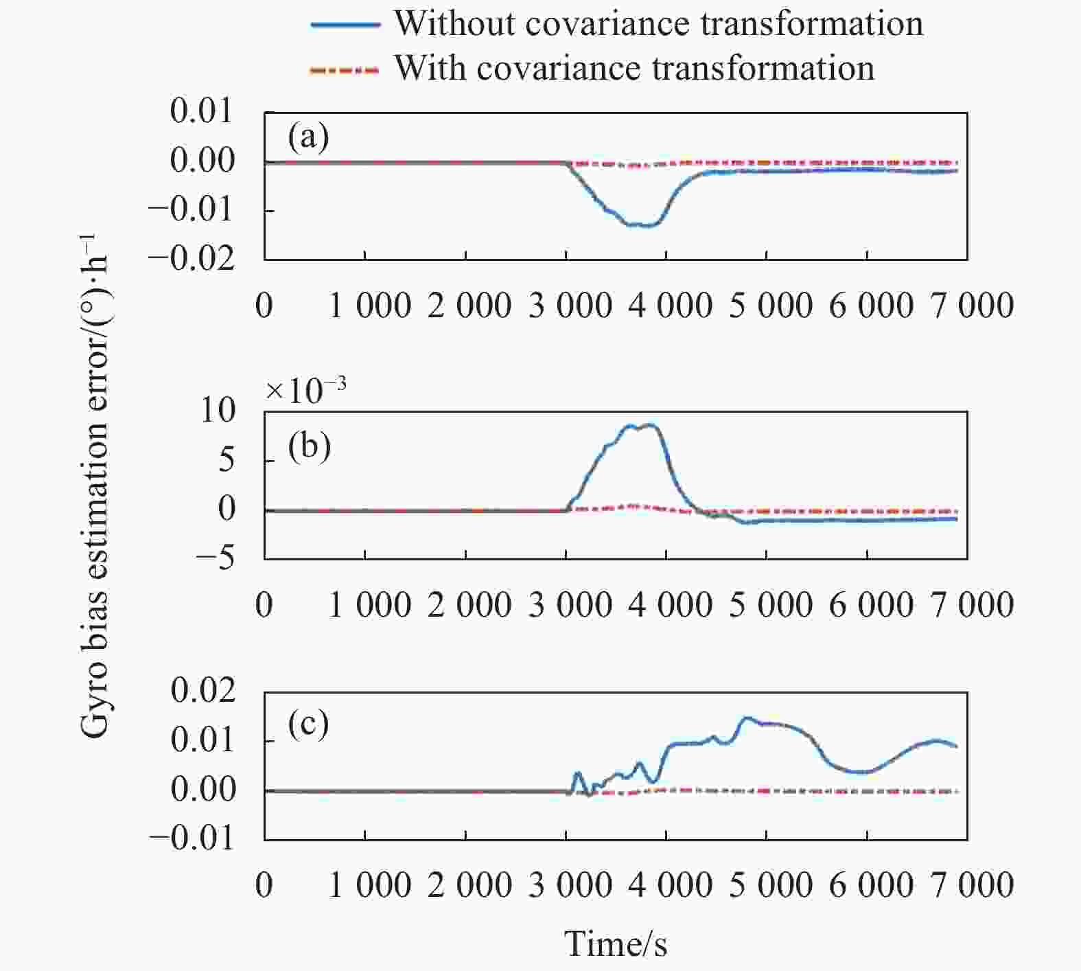
Figure 5. Relative estimation error of the gyro bias
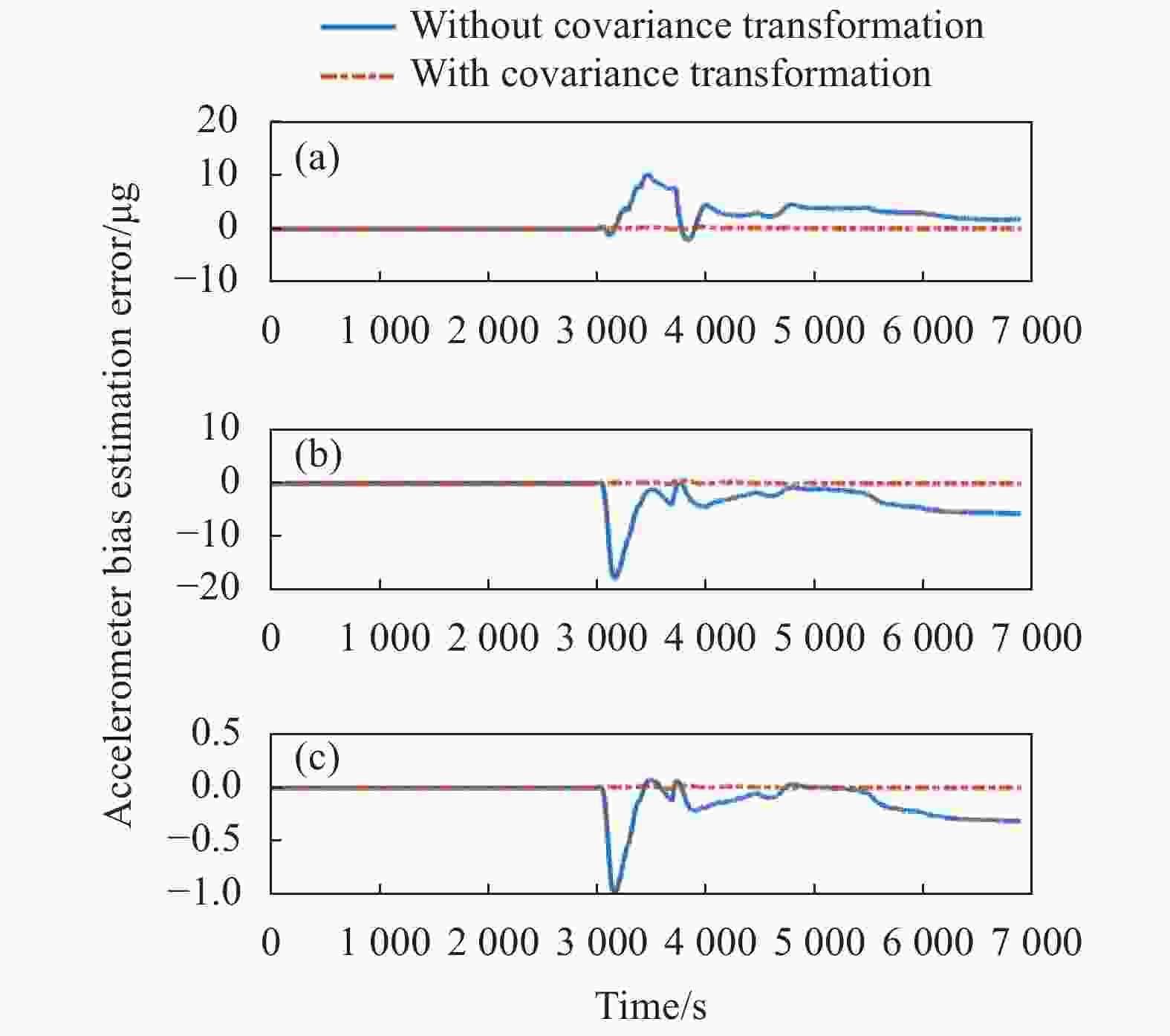
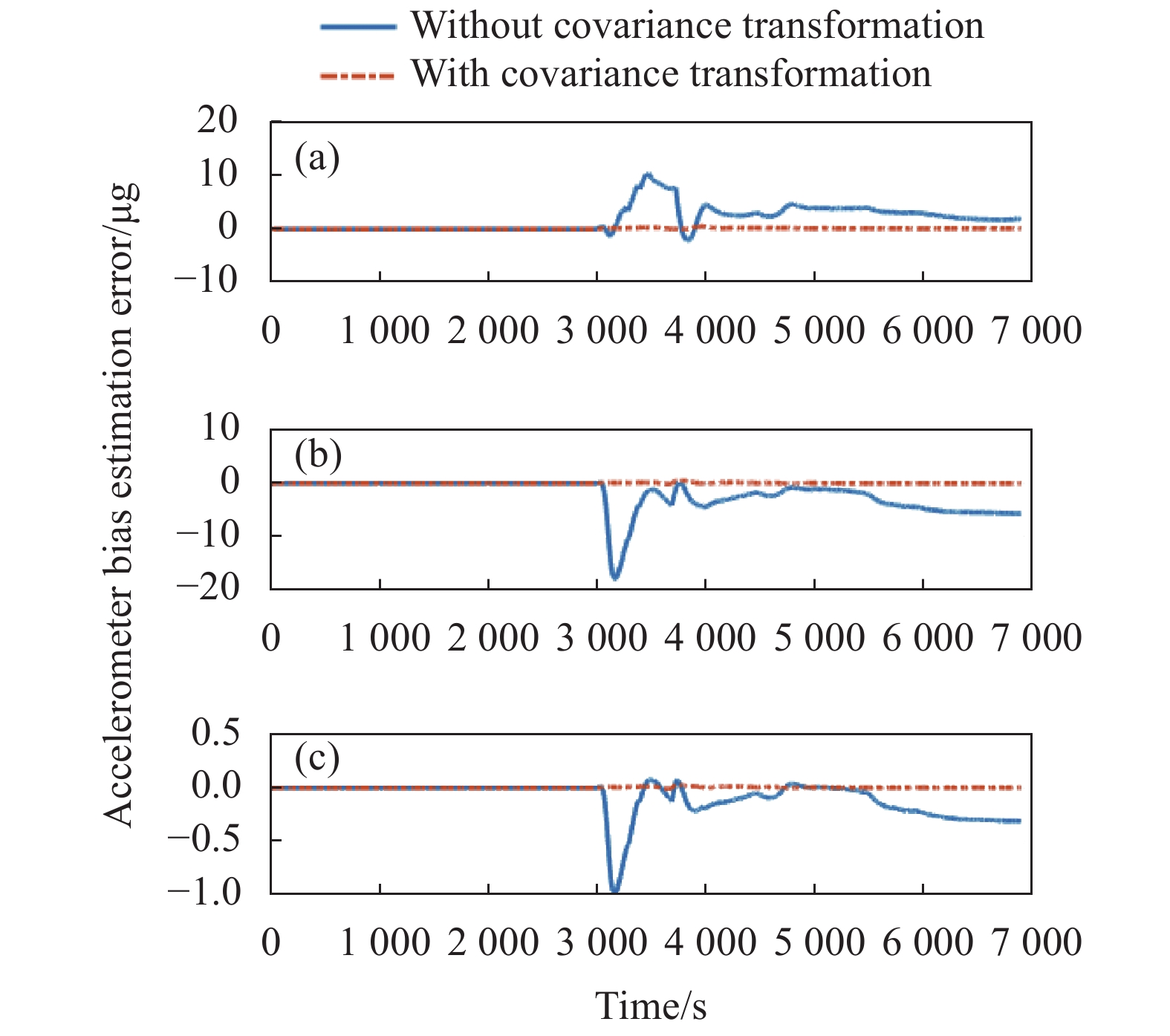
Figure 6. Relative estimation error of the accelerometer bias
如图3所示,在姿态误差中,航向角的估计误差最大,振荡幅值达到了4′。由于车载实验的运动主要以匀速直线运动为主,因此航向角可观测度较低,滤波器结构的改变容易引起震荡。
如图4所示位置的振荡幅度小于2 m。位置振荡较小的原因在于RLG INS/GNSS组合导航滤波器以GNSS提供的速度、位置信息作为观测量,不断依靠外部观测对RLG INS解算结果进行修正。
如图5、图6所示,陀螺、加速度计常值零偏估计误差最大可达0.015 (°)/h与20 μg。陀螺和加速度计的零偏虽然均用体坐标系表示,但由于协方差矩阵中非对角元素为非零值,受其他误差状态交叉耦合的影响,陀螺、加速度计零偏估计值也表现出了不稳定性。
图3~图6的结果表明,在导航坐标系转换过程中,基于协方差变换方法的组合导航解算结果与参考结果具有一致性,没有出现振荡情况。而无协方差变换的组合导航的解算参数在进入极区时出现了剧烈振荡情况,需要1000 s以上的时间才能够收敛,部分状态收敛到错误值。
统计六组跑车实验的结果,取状态估计值振荡误差的峰值,得到表1、表2。
Number Attitude error/(′) Velocity error/m·s−1 Position error/m Gyro bias error/(°)·h−1 Accelerometer bias error/μg 1 0.03 0.0004 0.2 0.001 0.24 2 0.01 0.002 0.18 0.002 0.22 3 0.14 0.0028 0.2 0.003 1.6 4 0.26 0.0004 0.12 0.002 0.38 5 0.02 0.0014 0.14 0.001 0.18 6 0.01 0.001 0.04 0.001 0.1 Average 0.08 0.0013 0.15 0.002 0.45 Table 1. Peak value of state estimation error with covariance transformation
Number Attitude error/(′) Velocity error/m·s-1 Position error/m Gyro bias error/(°)·h-1 Accelerometer bias error/μg 1 3.8 0.06 3.8 0.074 19.4 2 4.78 0.07 4 0.06 18.1 3 6.04 0.116 5.6 0.014 55.2 4 5.26 0.012 1.56 0.018 10.2 5 4.96 0.032 1.8 0.14 23.1 6 1.42 0.008 0.16 0.008 11 Average 4.38 0.05 2.82 0.052 22.82 Table 2. Peak value of state estimation error without covariance transformation
从表中数据可以看出,无协方差变换引起的姿态误差最高达到了6′左右,其余导航参数也有不同程度的震荡。使用协方差变换后,振荡幅值减少一两个数量级,实现了坐标系的平滑切换,提高了导航精度。
-
通过半实物仿真实验验证算法在高纬度下的适用性。纯数学仿真难以构建准确的RLG INS与GNSS的误差模型,采用纬度增量法进行高纬度仿真将更具备说服力[14]。
用纬度增量法将实测跑车实验数据数据转换至74 °纬线附近,得到一组半实物仿真数据。设定纬度大于74 °时进入极区。以格网系下的导航结果作为参考,下面给出有无协方差变换条件下导航参数比较,如图7~图10所示。
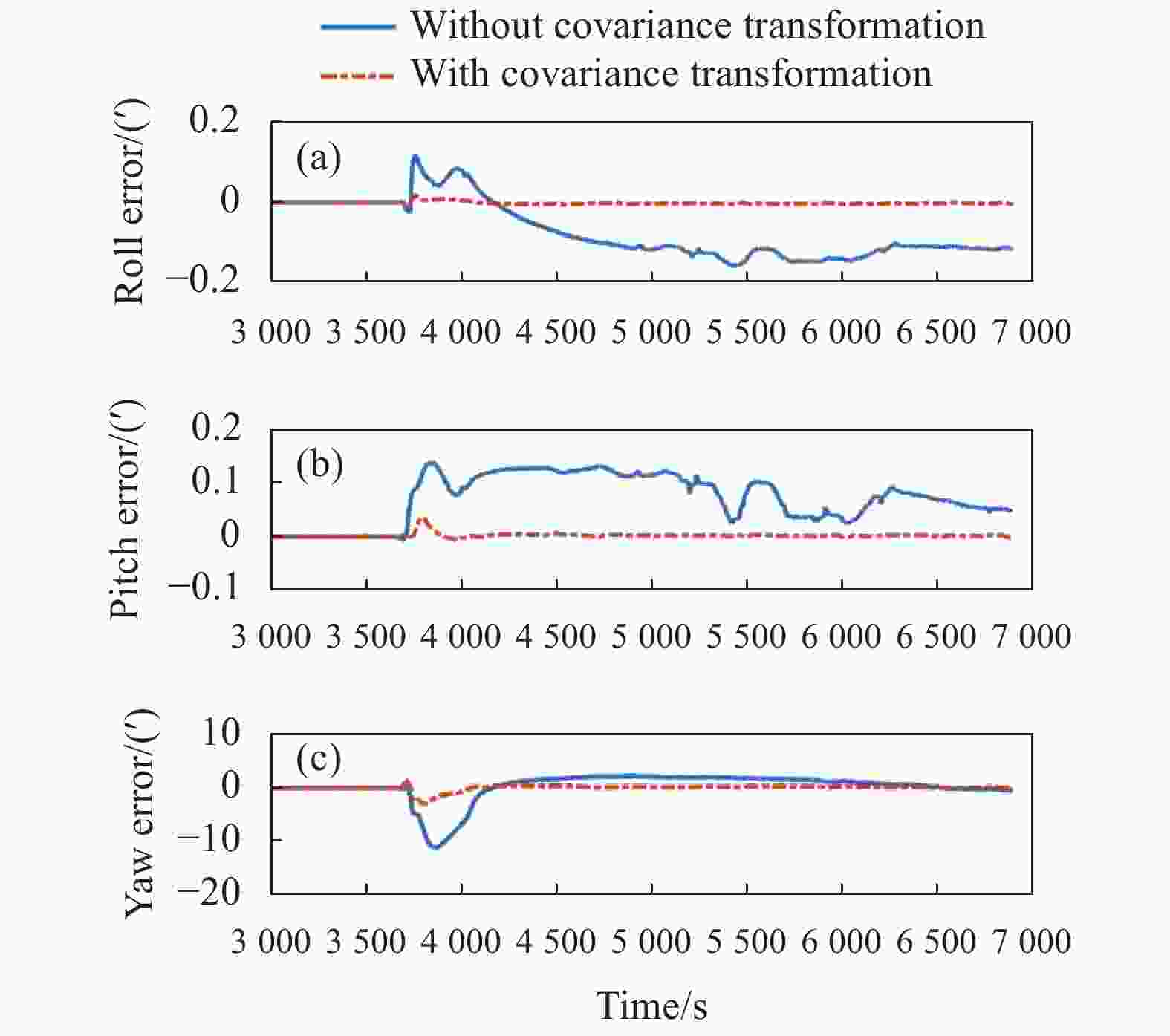
Figure 7. Relative attitude error in simulation experiment
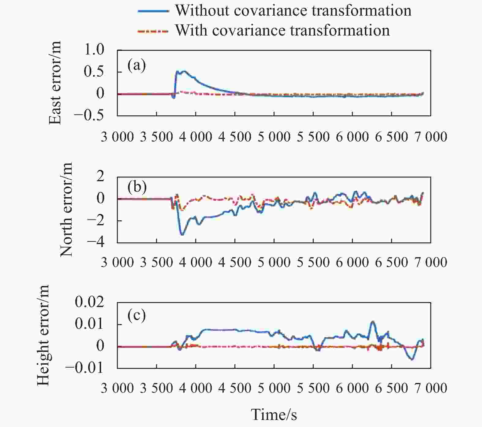
Figure 8. Relative position error in simulation experiment
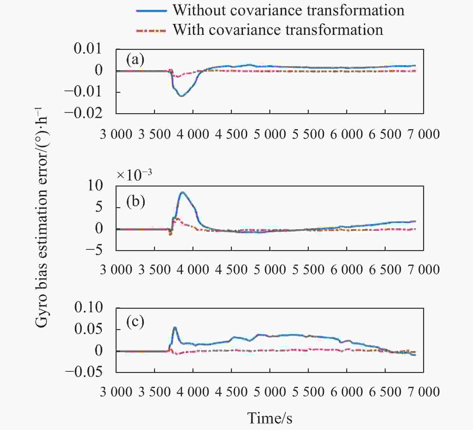
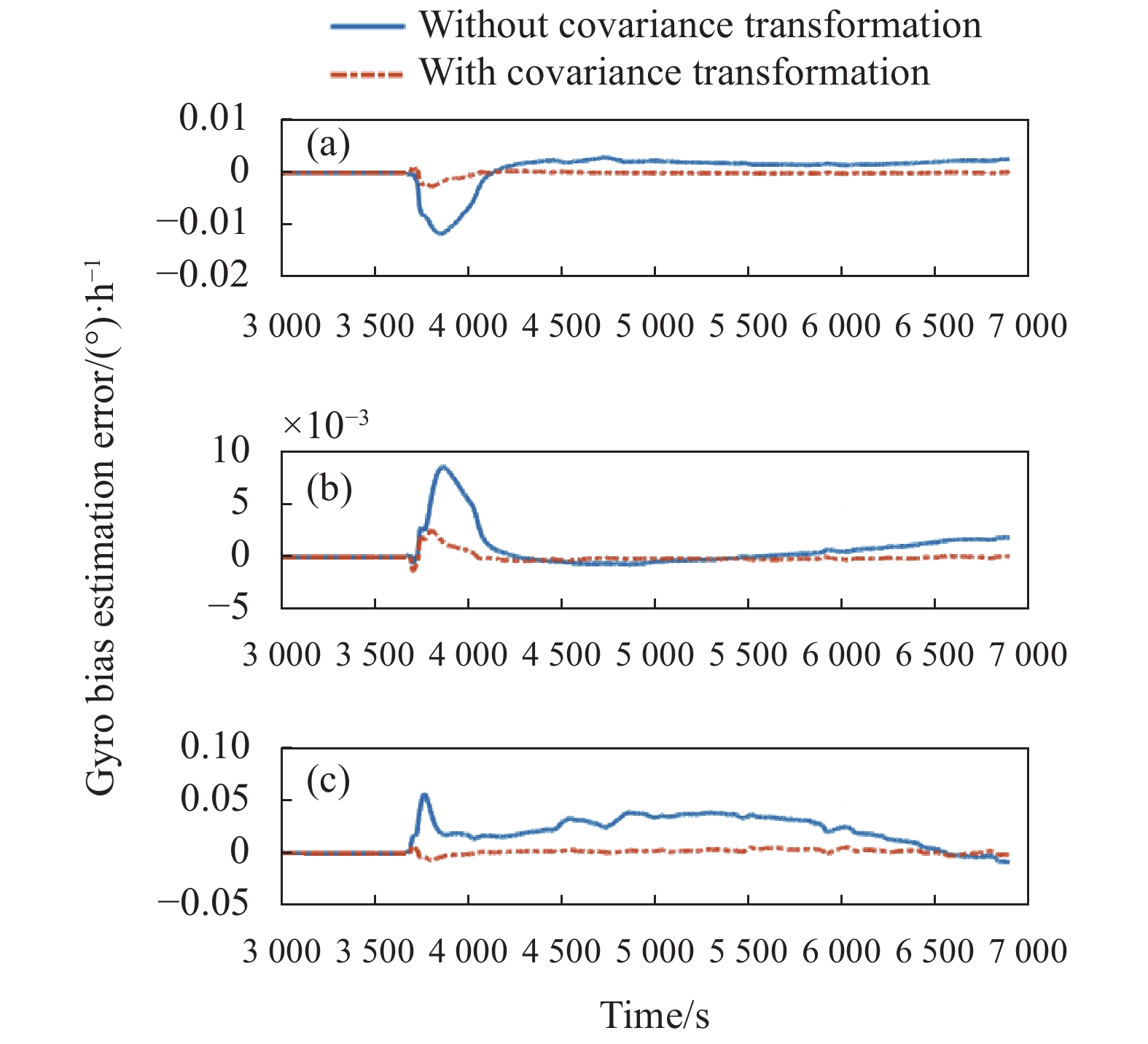
Figure 9. Relative estimation error of the gyro bias in simulation experiment

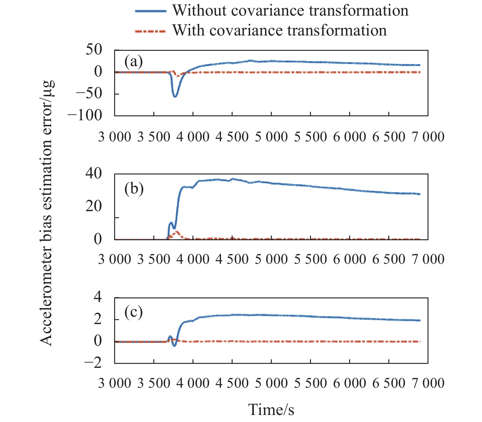
Figure 10. Relative estimation error of the accelerometer bias in simulation experiment
在仿真实验中,载车于3655 s时进入极区。如图7所示,由于载车机动性较弱,且高纬度地区可观测度进一步下降,无协方差变换条件下导航坐标系的切换引起的姿态误差增大。其中,航向角误差达到了10′。图8给出了位置误差的峰值4 m。图9、图10为陀螺与加速度计的零偏估计曲线。由于载车机动性较弱导致系统状态可观测度低,而高纬度地区则会造成可观测度进一步下降,所以没有协方差变换的情况下,陀螺与加速度计的零偏估计无法完全收敛至准确值,出现收敛错误。而存在协方差变换时,零偏估计的速度以及准确性都得到提高。
协方差变换方法是在不改变地理系加格网系作为导航坐标系的基础上寻找平滑切换的方法。该方法相比直接切换[11]可以有效降低切换坐标系带来的振荡误差。而相比各类间接算法[12],协方差变换法不仅从原理上解决了误差振荡的问题,也有利于在原有的基础上进行系统升级。
-
航空飞行器跨极区飞行进行导航坐标系转换时,由于滤波器结构变化,会产生额外的导航误差。文中针对这个问题,提出了基于协方差变换的RLG INS/GNSS组合导航算法,推导建立了系统误差状态及其协方差矩阵在地理坐标系及格网坐标系之间的转换关系,设计了具有滤波状态一致性的组合导航滤波器,通过实验对算法的有效性进行了验证。经实验验证,导航坐标系转换过程中如果不考虑滤波器结构的改变问题,会引起滤波不稳定,进而导致解算误差增大。在使用协方差变换算法后,滤波状态实现了平滑过渡,系统状态估计相对误差减小一个数量级,导航精度得以得到保证。


 DownLoad: