Volume 50 Issue 12
Dec.  2021
Turn off MathJax
Article Contents

Huo Hongyu, Gou Yudan, Yang Qingdong, Li Juan, Zhao Bangbo, Yang Huomu, Wang Jun. Design of beam homogenizing device at receiving end for laser wireless power transmission[J]. Infrared and Laser Engineering, 2021, 50(12): 20210102. doi: 10.3788/IRLA20210102
Citation: Huo Hongyu, Gou Yudan, Yang Qingdong, Li Juan, Zhao Bangbo, Yang Huomu, Wang Jun. Design of beam homogenizing device at receiving end for laser wireless power transmission[J]. Infrared and Laser Engineering, 2021, 50(12): 20210102. doi: 10.3788/IRLA20210102

Design of beam homogenizing device at receiving end for laser wireless power transmission

doi: 10.3788/IRLA20210102
  • Received Date: 2021-02-09
  • Rev Recd Date: 2021-03-10
  • Available Online: 2022-01-06
  • Publish Date: 2021-12-31
  • In the laser wireless power transmission, the ununiform distribution of laser light intensity and the mismatching of laser spot and photovoltaic cells shape will lead to the decrease of photoelectric conversion efficiency, local over temperature, and the damage of photovoltaic cells under extreme conditions. A laser receiver was designed based on the distributed homogenization method. Firstly, the light shaping diffuser was used to homogenize the beam in each sub-region of the photovoltaic cells, and then the optical tube was used for the second homogenization and beam shaping. For 1 cm×1 cm photovoltaic cells, the influence of the diffuse-angle of the laser shaping diffuser and the height of the optical tube on the beam homogenization effect was analyzed. The coupling efficiency ηc of the optimized laser receiver was more than 95%, and the light intensity nonuniformity Δ was less than 0.05. In addition, the laser receiver was not sensitive to the laser incident angle. When the incident angle was 20°, the coupling efficiency ηc was more than 80%. A laser wireless power transmission system based on 3×3 photovoltaic cells chip array was built. After using the designed laser receiver, the light intensity nonuniformity was reduced from 0.34 to 0.12, and the conversion efficiency of photovoltaic cell was improved by 65%. Compared with normal incidence of laser, the change of conversion efficiency was less than 20% when the laser incident angle was 18°. The results show that the laser receiver can effectively improve the light intensity uniformity at the receiver and the photoelectric conversion efficiency of the system. Meanwhile the laser receiver is insensitive to the laser incident angle. So the optical receiver can play an important role in laser wireless power transmission.
  • [1] Thibert T, Hellin M L, Loicq J, et al. Performance of solmacs, a high PV solar concentrator with efficient optics [J]. American Institute of Physics, 2012, 1477(1): 2225-2229.
    [2] Jin K, Zhou W. Wireless laser power transmission: A review of recent progress [J]. IEEE Transactions on Power Electronics, 2018, 34(4): 3842-3859.
    [3] Zhao C M, Wang Y S, Guo L D, et al. Development of laser wireless power transmission technology. [J]. Laser Technology, 2020, 44(5): 538-545. (in Chinese)
    [4] Glaser P E. Power from the sun: Its future [J]. Science, 1968, 162(3856): 857-861.
    [5] Steinsiek F. Wireless power transmission experiment as an early contribution to plane-tary exploration missions[C]//54th International Astronautical Congress, 2003, Bremen, Germany: IAF, 2003: 169-176.
    [6] Lockheed Martin Aeronautics Company. Lockheed martin performs first ever outdoor flight test of laser powered UAS[DB/OL]. [2012-08-07]. https://www.edn.com/electronicsproducts/electronic-product-releases/opto-electronics-products/4391875/Lockheed-Martin-P-erforms-First-Ever-Outdoor-Flight-Test-Of-Laser-Powered-UAS.
    [7] He T, Yang S H, Zhang H Y, et al. Experiment of space laser power transmission and conversion with high efficiency [J]. Chinese Journal of Lasers, 2013, 40(3): 0317001. (in Chinese) doi:  10.3788/CJL201340.0317001
    [8] Shen D, Zhang L, Ma H, et al. Research on wireless power transmission system between satellites[C]//Wireless Power Transfer Conference (WPTC), 2016. New York: IEEE, 2016: 1-4.
    [9] Motohiro T, Takeda Y, Ito H, et al. Concept of the solar-pumped laser-photovoltaics combined system and its application to laser beam power feeding to electric vehicles [J]. Japanese Journal of Applied Physics, 2017, 56(8S2): 08MA07. doi:  10.7567/JJAP.56.08MA07
    [10] Meng X X, Shen J S, Shi D L, et al. Secondary concentration of laser wireless power transmission receiving system [J]. Infrared and Laser Engineering, 2017, 46(7): 0705001. (in Chinese)
    [11] Hua W S, Liu X G, Zhang D M. Output characteristics of single-junction GaAs photovoltaic cell irradiated by laser [J]. Laser & Infrared, 2016, 46(12): 1463-1466. (in Chinese) doi:  10.3969/j.issn.1001-5078.2016.12.005
    [12] Yu Jeco-Espaldon B M, Sogabe T, Ahsan N, et al. Temperature dependence of luminescence coupling effect in InGaP/GaAs/Ge triple junction solar cells [J]. Journal of Photonics for Energy, 2018, 8(2): 022602.
    [13] Shu B F, Shen H, Liang Q B. Structure and performance optimization of concentrator photovoltaic system receiver [J]. Acta Energiae Solaris Sinica, 2010, 31(2): 185-190. (in Chinese)
    [14] Liu X G, Hua W S, Liu X, et al. Design of photovoltaic receiver with high circuitry efficiency for laser wireless power transmission system [J]. Laser Journal, 2015, 36(12): 100-103. (in Chinese)
    [15] Sharma P, Wilkins M, Schriemer H, et al. Concentrating optical system optimization for 3-and 4-junction solar cells: Impact of illumination profiles [J]. Journal of Photonics for Energy, 2017, 7(1): 014501. doi:  https://doi.org/10.1117/1.JPE.7.014501
    [16] Kansal I, Pachauri R. Mathematical puzzle based PV array configuration for GMP enhancement under non-uniform irradiation [J]. EAI Endorsed Transactions on Energy Web, 2020, 8(23): 165915.
    [17] Lawrence Livermore National Laboratory. Solar Power Beaming: From Space to Earth[R]. USA: LLNL, 2009: 412782.
    [18] Ortabasi U, Friedman H W. PowerSphere: A novel photovoltaic cavity converter using low bandgap TPV cells for efficient conversion of high power laser beams to electricity[C]//2004 AIP Conference Proceedings. New York: American Institute of Physics, 2004, 738: 142-152.
    [19] Parise R J. Future all-electric transportation communication and recharging via wireless power beam[C]//Proceedings of SPIE, 2001, 4214: 171-179.
    [20] Zhang J D, Guo C H, Yu H F, et al. Research on laser wireless power transmission and receiving device [J]. Spacecraft Engineering, 2015, 24(1): 13-17. (in Chinese) doi:  10.3969/j.issn.1673-8748.2015.01.003
    [21] Becker D E, Chiang R, Keys C C, et al. Photovoltaic-concentrator based power beaming for space elevator application [J]. AIP Conference Proceedings, 2010, 1230: 271-281.
    [22] Nicodemus F, Richmond J C, Hsia J J, et al. Geometrical Considerations and Nomenclature for Reflectance[M]. District of Columbia: National Bureau of Standards, 1977: 94–145.
    [23] Harvey J E. Light-scattering characteristics of optical surfaces[D]. Arizona: The University of Arizona, 1976: 107–130.
    [24] Sun Chengming, Zhao Fei, Zhang Ze. Stray light analysis of large aperture optical telescope using Trace-Pro[C]//SPIE International Symposium on Optoelectronic Technology and Application 2014: Imaging Spectroscopy; and Telescopes and Large Optics. 2014, 9298: 92981F.
  • 加载中
通讯作者: 陈斌, bchen63@163.com
  • 1. 

    沈阳化工大学材料科学与工程学院 沈阳 110142

  1. 本站搜索
  2. 百度学术搜索
  3. 万方数据库搜索
  4. CNKI搜索

Figures(8)  / Tables(1)

Article Metrics

Article views(249) PDF downloads(49) Cited by()

Related
Proportional views

Design of beam homogenizing device at receiving end for laser wireless power transmission

doi: 10.3788/IRLA20210102
  • 1. College of Electronic Information, Sichuan University, Chengdu 610065, China
  • 2. Suzhou Everbright Photonics Co., Ltd, Suzhou 215163, China

Abstract: In the laser wireless power transmission, the ununiform distribution of laser light intensity and the mismatching of laser spot and photovoltaic cells shape will lead to the decrease of photoelectric conversion efficiency, local over temperature, and the damage of photovoltaic cells under extreme conditions. A laser receiver was designed based on the distributed homogenization method. Firstly, the light shaping diffuser was used to homogenize the beam in each sub-region of the photovoltaic cells, and then the optical tube was used for the second homogenization and beam shaping. For 1 cm×1 cm photovoltaic cells, the influence of the diffuse-angle of the laser shaping diffuser and the height of the optical tube on the beam homogenization effect was analyzed. The coupling efficiency ηc of the optimized laser receiver was more than 95%, and the light intensity nonuniformity Δ was less than 0.05. In addition, the laser receiver was not sensitive to the laser incident angle. When the incident angle was 20°, the coupling efficiency ηc was more than 80%. A laser wireless power transmission system based on 3×3 photovoltaic cells chip array was built. After using the designed laser receiver, the light intensity nonuniformity was reduced from 0.34 to 0.12, and the conversion efficiency of photovoltaic cell was improved by 65%. Compared with normal incidence of laser, the change of conversion efficiency was less than 20% when the laser incident angle was 18°. The results show that the laser receiver can effectively improve the light intensity uniformity at the receiver and the photoelectric conversion efficiency of the system. Meanwhile the laser receiver is insensitive to the laser incident angle. So the optical receiver can play an important role in laser wireless power transmission.

  • 激光无线能量传输(laser wireless power transmission, LWPT)作为无线能量传输四种主要手段之一,具有方向性好、功率密度高和传输距离远的特点,在给直升飞机、卫星、空间站和探月机器人供电方面具有潜在的应用前景[1-3]。1968年,美国Glaser博士第一次提出激光无线能量传输概念[4],此后激光无线能量传输技术快速发展。2003年,Steinsiek利用激光无线能量传输,驱动地面的小车正常工作,激光传输距离30~200 m,使用的InGaP电池板光电转换效率25%[5];2012年,洛克希德·马丁公司对无人机进行激光无线充电,无人机空中续航时间由2 h提高到了48 h以上[6];2013年,北京理工大学何滔等设计的地面激光无线能量传输系统整体的电-光-电转换效率达到18%[7];2014年,山东航天电子技术研究所在飞艇之间进行动态激光无线能量传输实验,飞艇之间距离50~100 m,速率5 m/s,实验最大传输效率达到16.08%[8]。2017年,日本名古屋大学提出了太阳光驱动道路两边的激光器对汽车进行无线供能的方案,并对此设计了一个高效的太阳能抽运激光器和太阳能跟踪系统,实验显示跟踪误差仅1 mrad,且不易受风的影响[9]

    由于激光光强分布不均匀和大气湍流的影响,在光电池接收端会出现激光光强分布不均匀和激光光斑与电池形状不匹配的问题,导致系统光电转换效率降低[10],热管理困难[11-12],极端条件下甚至对光电池造成损伤[13]。此外,光强分布不均匀还会影响电池的串并联电阻[14-15],降低负载传输效率[16]。因此,在光电池前端对激光进行光束匀化和整形是实现高效无线能量传输的一个重要手段。

    近年,在光电池前端主要采用会聚型、能量球和平板型三种接收装置对激光进行光束匀化和整形。会聚型通常采用聚焦透镜将光斑会聚到光电池上,可以提高能量利用率[7, 17];能量球通过在能量球内部多次反射提高光斑均匀性[18];平板型结构中,激光直接照射在平铺电池板上,具有安装方便、易于跟踪等优点[19-20]。组合式激光接收装置也是研究热点之一。2010 年,NASA 在激光无线能量传输驱动太空电梯实验中[21],采用菲涅耳透镜和铝制光学漏斗构成组合式激光接收装置,单个接收端模块光电转换效率达到了35%。2016年,山东航天电子技术研究所孟祥翔等人进行激光无线能量传输实验[10],由菲涅耳透镜和梯形光学漏斗构成组合式激光接收装置,将电池转换效率提升了6%~7%。总体来看,采用单一的激光接收装置难以同时实现整形和匀化,基于菲涅耳透镜的组合式激光接收装置存在体积较大,安装不易的问题。此外,光电池阵列单元间存在间隙,造成激光能量利用率低。

    基于分布式匀化的思想,设计了一种新型的激光接收装置,将光电池接收前端划分为多个接收子区域,在每个子区域对入射激光独立匀化和整形,降低了电池阵列单元间隙造成的能量损失。采用光学整形扩散片(Light Shapping Diffusers,LSD)在光电池子区域进行光束初次匀化,然后利用光学漏斗进行二次匀化和整形,同时解决了接收端激光光强分布不均匀和激光光斑与电池形状不匹配的问题。此外,该激光接受装置还具有体积小、安装方便和对激光入射角不敏感的优点。

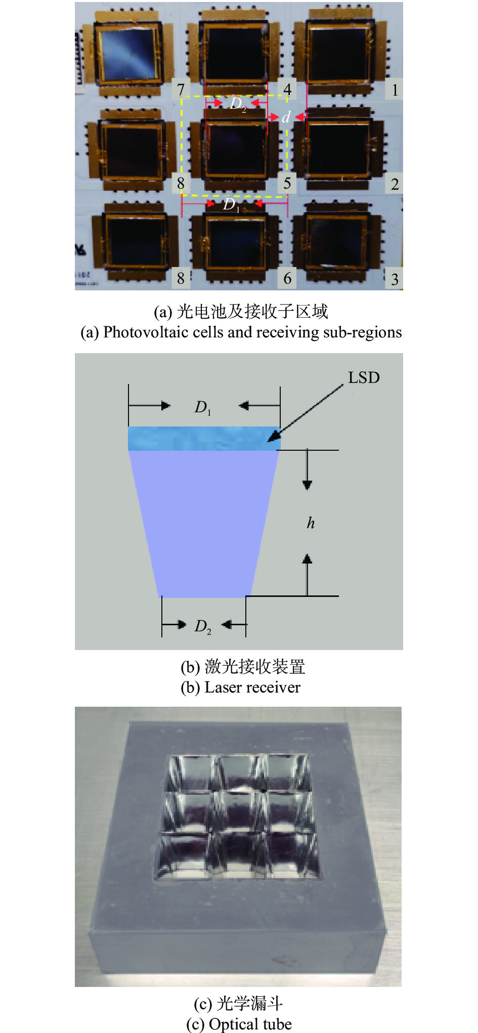
    • 光电池阵列呈3×3排布,光电池芯片面积为1 cm×1 cm,间距d=10 mm。每个光电池芯片的接收子区域如图1(a)的虚线区域所示。激光接收装置由LSD和光学漏斗组成,如图1(b)所示。光学漏斗高度为h,前端是边长为D1=20 mm的正方形,与LSD贴合连接,后端是边长为D2=10 mm的正方形,与电池贴合连接。入射激光经过LSD随机粗糙表面产生漫透射,实现初次匀化[22-24]。初次匀化后的激光通过镀有高反膜的光学漏斗,经内壁反射实现能量的重新分配,最终实现二次匀化和整形。每个接收子区域有一个激光接收装置,与光电池阵列同样呈3×3排布,如图1(c)所示。

      Figure 1.  Diagram of model

    • 在激光无线能量传输中,评价光束匀化主要考虑光强分布均匀性和耦合效率。通过将CCD拍摄的光斑图导入matlab,得到各像素点灰度值,以其表征光强分布,则光强不均匀度Δ定义为:

      式中:X为光斑各像素点灰度值;$\overline X $为光斑各像素点灰度平均值;N为光斑像素点的总数。Δ越小表示光强越均匀。

      耦合效率用ηc表示,计算公式如下:

      式中:Pout为激光接收装置输出光功率;Pin为激光接收装置输入光功率。

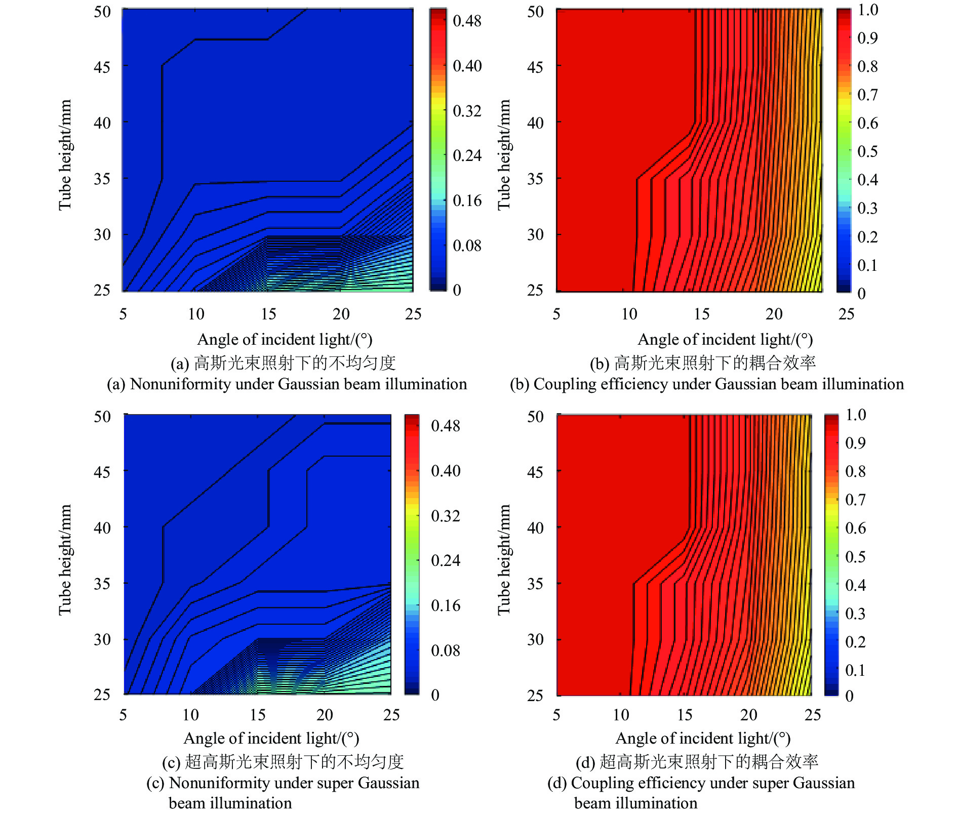
      根据Luminit公司的LSD散射数据库建立模型,分别在高斯和超高斯光束照射下进行模拟。激光接收装置前端光强不均匀度在高斯和超高斯光束照射下分别为0.39和0.29,经接收装置后的不均匀度和耦合效率如图2所示,图(a)和(b)分别为高斯光束照射下,采用不同扩散角度的LSD和不同高度的光学漏斗时的不均匀度;图(c)和(d)分别为超高斯光束照射下,采用不同扩散角度的LSD和不同高度的光学漏斗时的耦合效率;图(e)为光线追迹图。

      Figure 2.  LSD with different diffuse-angles and optical tube with different heights

      图2中,扩散角度0°表示不加LSD。由图2(a)(c)可见,激光接收装置不加LSD仅采用光学漏斗时,因部分光线没有经过光学漏斗内壁反射,直接从漏斗后端出射,导致均匀性较差。采用LSD后,入射激光的发散角增大,光学漏斗内壁反射光线的数量和反射次数都在增加,均匀性大为改善。此外,采用LSD改变入射激光发散角比菲涅耳透镜或球面镜等更有优势,例如要实现入射激光发散角为10°,后两者会使激光接收装置的高度增加约55 mm,这个距离与菲涅耳透镜或球面镜的焦距近似相等。通常增大LSD的扩散角度对光强匀化效果影响不大,反而会使耦合效率降低;光学漏斗的高度增加对光强均匀性和耦合效率的提升也有一定限度。因此文中选择10°扩散角度的LSD,为减小光学接收装置体积,降低加工难度,文中设计的光学漏斗高度选择25~50 mm。

      采用扩散角度为10°的LSD,光学漏斗高度取值范围为25~50 mm,激光以不同角度入射时的光强均匀性和耦合效率如图3所示。由图可见,在高斯和超高斯光束照射下,当光束入射角为10°时,光强不均匀度Δ<0.07,耦合效率ηc>95%。当入射角小于10°时,光学漏斗高度变化基本不会影响光强均匀性和耦合效率。为最大限度减小激光接收装置体积,光学漏斗高度可选择25 mm。

      Figure 3.  Light intensity uniformity and coupling efficiency with different incident angles of laser

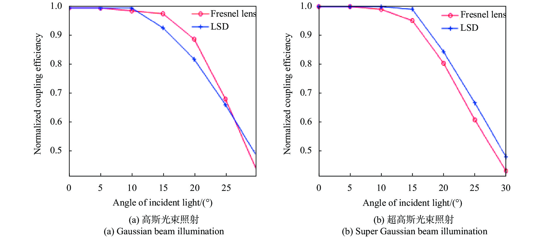
      与采用菲涅耳透镜和光学漏斗组成的激光接收装置[10, 21]相比,文中设计的激光接收装置具有体积小的优点。图4为在高斯光束和超高斯光束照射下,激光接收装置分别采用菲涅耳透镜和LSD与光学漏斗组合时,耦合效率ηc随入射角变化的仿真结果。由图可见,与正入射相比,入射角为20°时,两种情况下耦合效率变化均小于20%。当激光接收装置采用菲涅耳透镜时,如果光学漏斗高度低于80 mm,入射角的变化会导致光强均匀性较差,入射角为5°时,光强不均匀度就会大于0.24。相反,激光接收装置采用LSD后,光学漏斗高度为25 mm,入射角为10°时,光强不均匀度依然保持在小于0.07的范围。

      Figure 4.  Variation of coupling efficiency with angle of incident light of laser

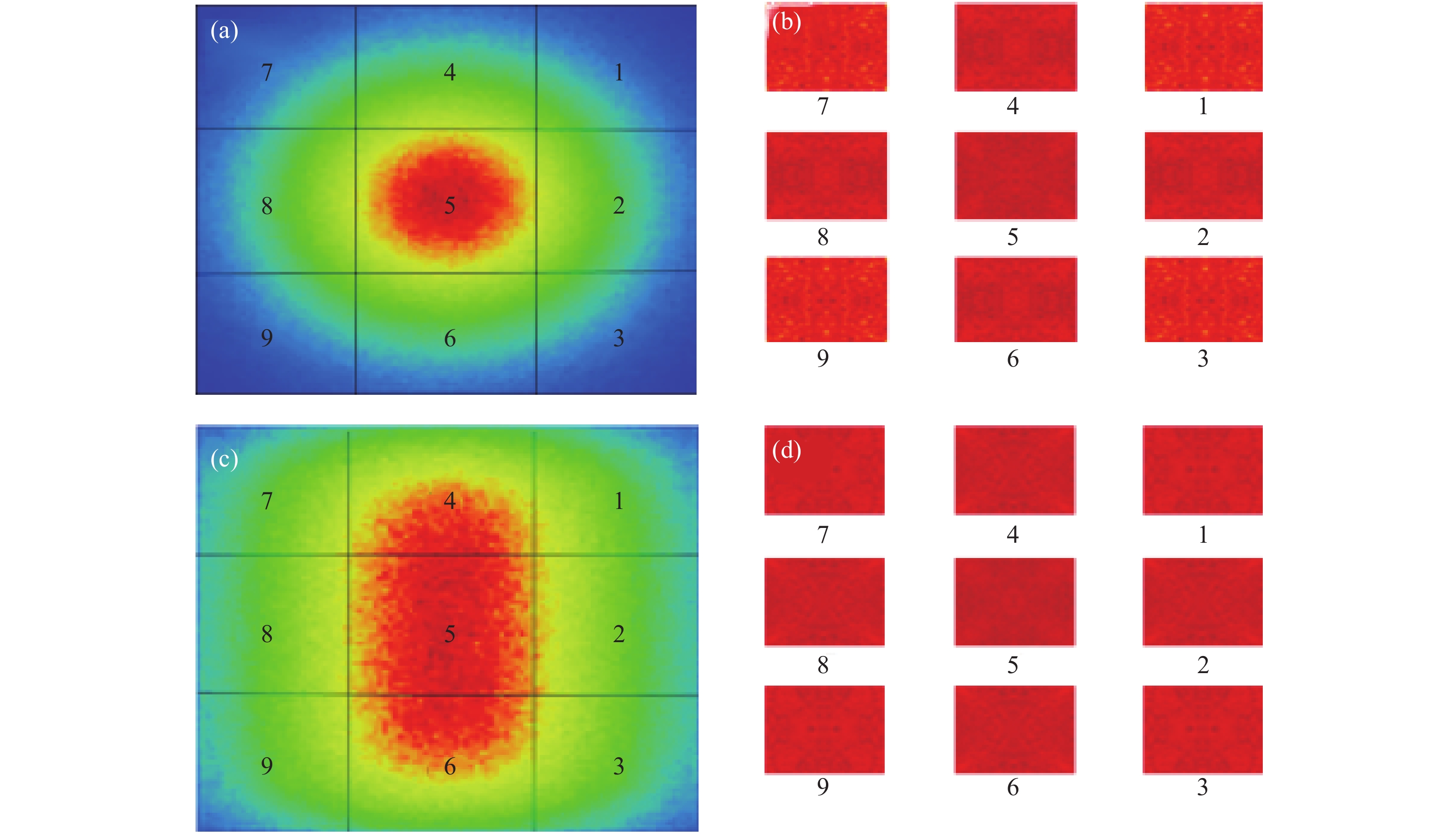
      采用3×3阵列激光接收装置,光电池位置编号为1~9,如图5所示。LSD的扩散角度为10°,光学漏斗的高度为25 mm,激光从光学漏斗前端正入射,激光接收装置接收到的能量占激光总能量的94.8%。模拟结果如图5所示,图(a)和(c)分别为高斯和超高斯光束照射下,激光接收装置前端的光强分布;图(b)和(d)分别为高斯和超高斯光束照射下,光电池上的光强分布。模拟结果表明,在高斯和超高斯光束照射下,耦合效率均大于95%;1~9号光电池的光强不均匀度在0.03~0.07之间。此外,1~9号位置入射激光光强分布的前后变化显示该设计对入射激光分布不敏感。

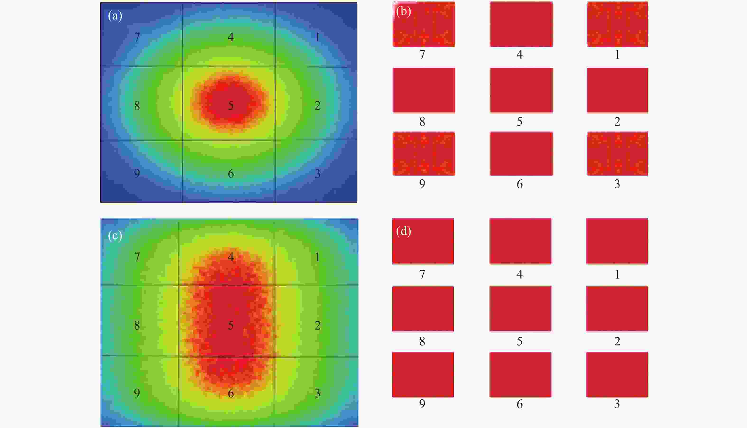
      Figure 5.  Simulation results of 3×3 receiver array. (a) Light intensity distribution in fore-end of laser receiver under Gaussian beam illumination; (b) Light intensity distribution on the photovoltaic cell under Gaussian beam illumination; (c) Light intensity distribution in fore-end of laser receiver under super Gaussian beam illumination; (d) Light intensity distribution on the photovoltaic cell under super Gaussian beam illumination

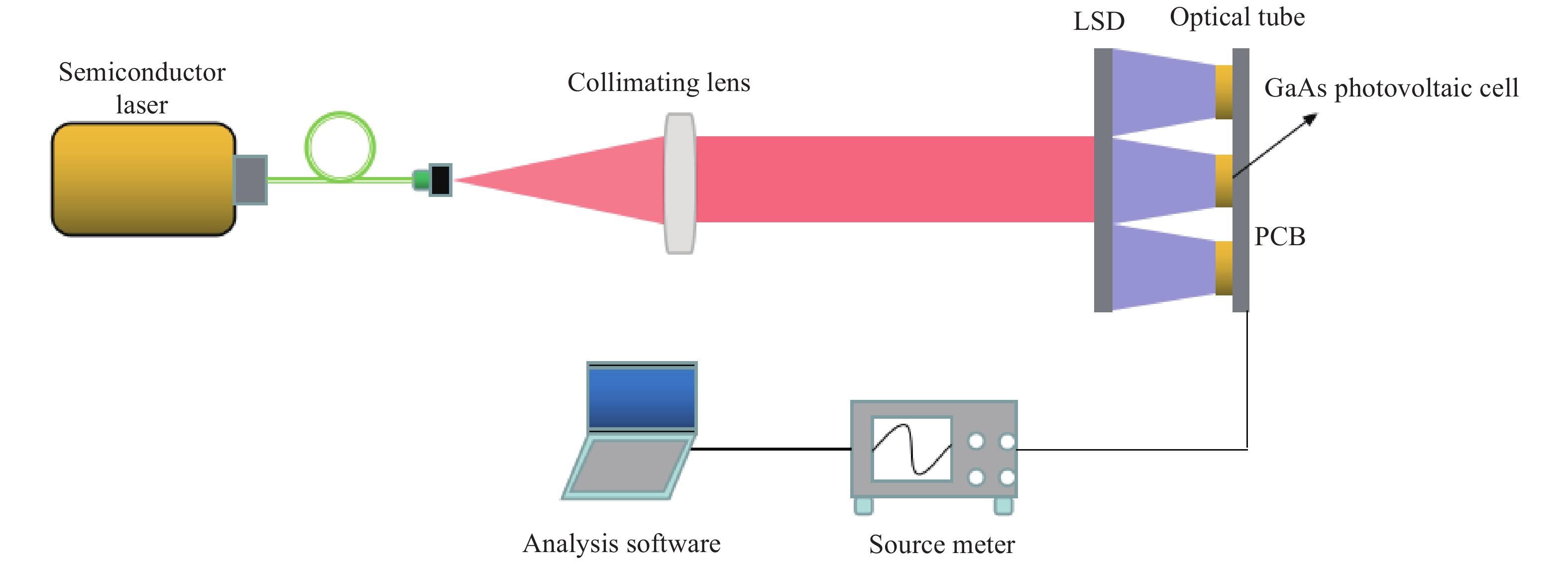
    • 图6为实验光路图。LSD采用扩散角度为10°的Luminit产品,对波长808 nm半导体激光的透过率为92%。LSD安装在光学漏斗前端,光学漏斗孔内壁贴铝箔做反射处理。光源为光纤耦合半导体激光器,输出波长为808 nm,激光接收装置前端接收到的能量占激光总能量的95%。实验对传输距离不做要求。光电池为单节GaAs。当测试光强不均匀度时,移走光电池,将一张白纸贴在光学漏斗后端,通过CCD拍摄白纸上的光斑,最后通过matlab计算光强不均匀度。

      Figure 6.  Experimental schematic for LWPT

      在实验室内进行实验,激光接收装置前端的光功率密度分别为0.08、0.15、0.24 W/cm2时进行测量,结果见表1。其中IsVo分别为不采用激光接收装置时的短路电流和开路电压;Is′和Vo′分别为采用激光接收装置时的短路电流和开路电压。用η表示光电池转换效率的提升值,计算公式如下:

      ParametersTest values
      Input optical power/W·m-20.080.150.24
      Is/mA74.4142.4211.5
      Vo/V1.031.051.06
      Is'/mA120.8231.6342.6
      Vo/V1.051.071.08
      η65.5%65.7%65.0%
      Δ0.120.120.12
      ηc74.6%75.8%73.47%

      Table 1.  Test values of different input optical power densities

      表1可见,采用激光接收装置后,光电池转换效率η提升约为65%,光强不均匀度Δ由0.34降低到0.12,耦合效率ηc约为74%。由于光学漏斗内壁铝箔的反射率仅为75%,导致光学接收装置的耦合效率只有74%,低于将光学漏内壁反射率设为75%时的仿真结果83%。此外,实验采用的LSD为聚碳酸酯材料制成,当激光处于较高光功率密度,可选择浮法玻璃材料制成的LSD,效果基本不变。

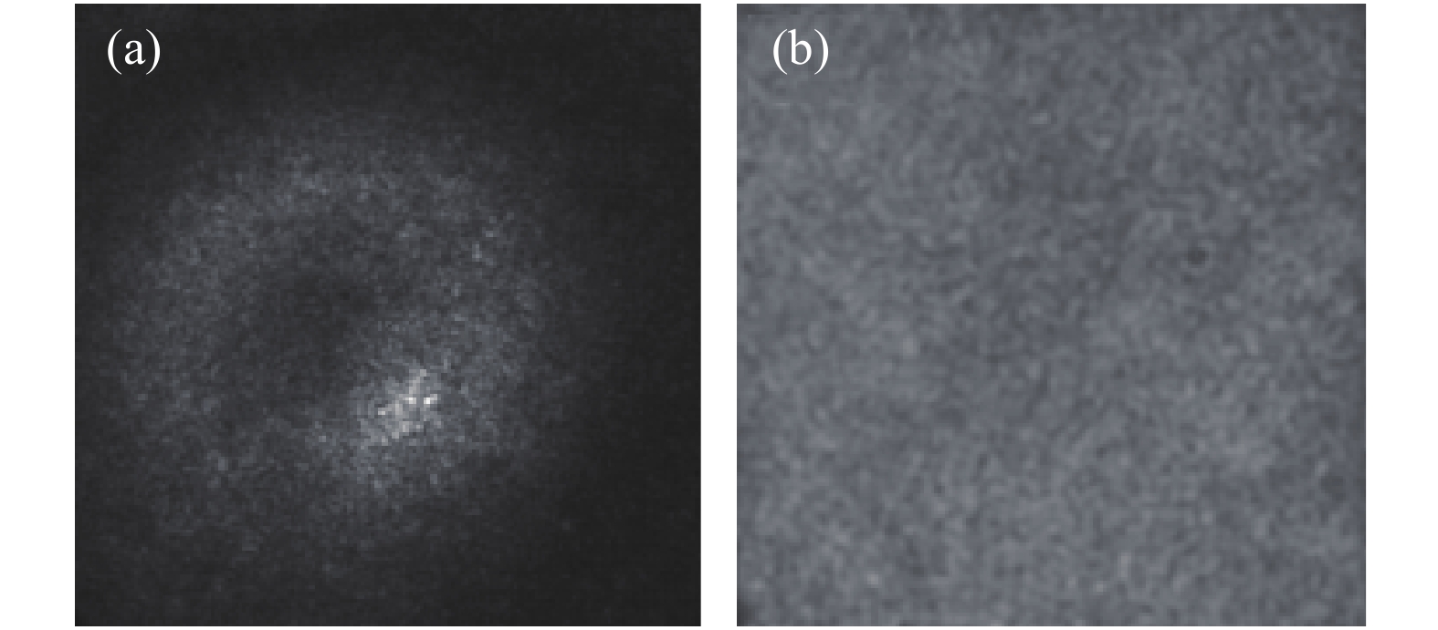
      实验中光强不均匀度与入射激光光强变化无关,图7为CCD拍摄的激光接收装置前端和后端的光斑图,可见光束经激光接收装置后均匀性有了很大改善。

      Figure 7.  Spot image taken by CCD. (a) Spot image in fore-end of laser receiver; (b) Spot image in back-end of laser receiver

      激光接收装置输入光功率密度分别为0.08、0.15、0.24 W/cm2时,改变激光入射角,测试光电池的短路电流和开路电压。图8示出入射角度对系统转化效率影响的拟合曲线。图中,纵坐标为1− ηsc。从图中可以看出:与正入射时相比,入射角为18°时,系统转换效率变化小于20%。与模拟值的20°相差为2°,基本验证了模拟结果,表明该激光接收装置对激光入射角不敏感。

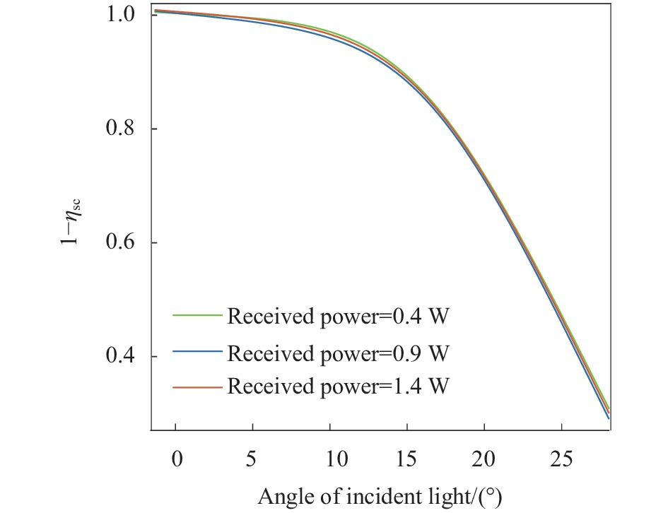
      Figure 8.  Influence of incident angle on system conversion efficiency

      ηsc表示系统的转换效率变化值,计算公式如下:

      式中:Is0为入射角0°时短路电流;Vo0为入射角0°时开路电压;Isi为入射角i°时短路电流;Voi为入射角i°时开路电压。

    • 文中基于分布式匀化思想,设计了一种用于激光无线能量传输的激光接收装置,将光电池接收前端划分为多个接收子区域,在每个子区域独立匀化和整形。模拟结果表明,在高斯光束照射下,光强不均匀度由0.39降低到0.05;在超高斯光束照射下,光强不均匀度由0.29降低到0.04。入射角为0°时的耦合效率ηc>95%,入射角为20°时的耦合效率ηc>80%。采用激光接收装置之后,实验测得光强不均匀度由0.34降为0.12,系统转换效率提升了65%;与正入射时相比,入射角为18°时,系统转换效率变化小于20%,给出了应用时适合的入射角范围。与采用菲涅耳透镜和光学漏斗组合的激光接收装置相比,设计的激光接收装置具有体积小,方便大规模集成的特点。

Reference (24)

Catalog

    /

    DownLoad:  Full-Size Img  PowerPoint
    Return
    Return