


-
随着光电对抗技术的不断发展,诱骗红外探测系统的能力及方式也逐渐多样化、复杂化,促使探测系统的抗干扰能力也要不断进步和发展。而红外双色复合导引模式能够取长补短,有效解决单一导引模式自身使用条件限制问题[1],提升导弹全天时/全天候适应能力、反隐身/抗干扰能力,提高打击目标精度。同时,多光谱干扰技术近年来也正迅猛发展,为了能在复杂战场环境中发挥作战效能,在双色探测系统研制、开发、设计等阶段,需要采用相应的方法对抗干扰性能进行模拟、仿真及测试等实验验证[2-4]。而国内现阶段缺少中长双色半实物验证手段,典型目标、自然背景以及人工干扰多光谱特征半实物模拟逼真度有待验证。
文中基于中长波双色探测系统抗人工干扰性能验证需求[5-7],对中长波双色目标和红外诱饵模拟仿真技术[8]进行研究和分析。建立某型战机和某型坦克目标中长波红外辐射模型,同时搭建红外诱饵中长波红外辐射模型以及运动模型。最后,基于中长波双色半实物仿真系统输出典型目标投放红外诱饵中长波红外仿真图像给某中长波双色产品,完成模拟仿真效果验证。
-
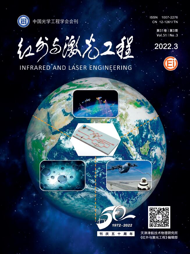
中长双色半实物仿真系统由双色目标模拟器,包括中波MOS电阻阵目标模拟器和长波DMD红外成像模拟器,目标模拟器控制台与控制计算机、弹体姿态控制台与控制计算机、主控计算机以及产品接口计算机组成,以VMIC网络为通讯介质,构成分布式实时半实物仿真系统[8-11],具体组成如图1所示。

Figure 1. Medium and long wave dual-color hardware-in-the-loop simulation system
如上图所示,主控系统可以同步控制弹体姿态模拟系统、目标姿态模拟系统、双色红外成像模拟器控制系统、弹体运动模拟系统以及探测系统的控制系统。通过弹体运动模拟系统设置不同弹道参数生成弹体和目标姿态模拟系统的控制指令、生成双色红外成像模拟器控制系统的目标与导弹运动参数,开展各典型弹道动态仿真。双色红外成像模拟器控制系统可设置双色目标/干扰模拟的控制参数,包括目标、干扰类型以及干扰投射参数、导弹飞行时目标的能量变化参数等;弹体姿态模拟系统和目标姿态模拟系统可以模拟目标相对导弹运动的视线角速度;探测系统的控制系统完成双色探测系统上电启动,控制探测系统实现陀螺指向搜索、跟踪,同时能够实时采集仿真过程中探测系统的相关输入输出信息,实时完成探测系统状态参数设置和工作状态控制。
-
中长双色半实物仿真系统核心部分是双色红外成像模拟器控制系统,由中波MOS电阻阵目标模拟器、长波DMD红外成像模拟器、双色通道定向复合光学系统组成,其双色红外成像原理示意图如图2所示。
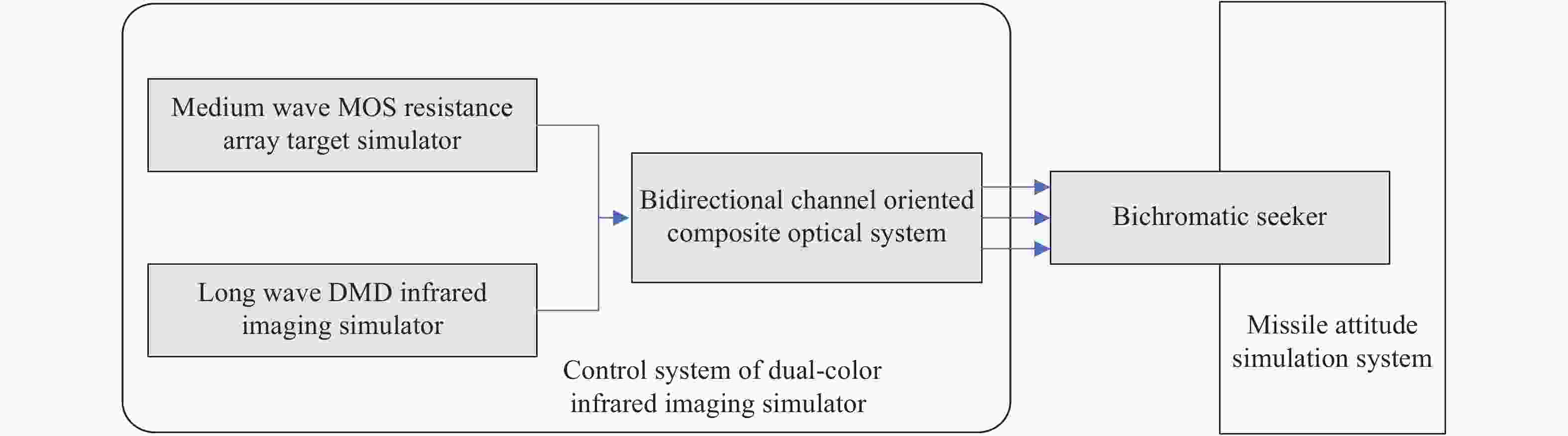
Figure 2. Principle of dual-color imaging
中波MOS电阻阵[9~10]目标模拟器采用MOS电阻阵作为核心器件,每个像素可单独控制加热,不需要照明光源,辐射温度范围大,具备模拟中波红外波段成像的优势。同时,国内MOS电阻阵列规模已经达到512×512,帧频最高达200 Hz,五年内MOS电阻阵分辨率将达到1024×1024;长波DMD红外成像模拟器,采用数字微镜阵列(Digital Micro mirror Device)作为核心器件,以可控温的面源黑体作为光源,采用反射式原理,通过对DMD芯片的调制输出动态图像。分辨率高,可达1024×768或更高,模拟辐射温度范围相对较小,一般为常温~100 ℃,为此用来模拟长波红外波段成像。
双色通道定向复合光学系统包含三反系统、双通道复合扩束场镜。其作用是将中波MOS电阻阵以及长波DMD系统产生的红外辐射通过透镜合成光束经过第一平面反射镜、第二平面反射镜、第一主反射镜、第二反射镜以及扩束场镜完成三次反射,入射合成光束通过双通道复合定向光学系统复合、准直、扩束后出射提供给双色探测系统入瞳面,双色合成出射光束达到系统完善耦合的目的,详细过程如图3所示。

Figure 3. Working principle of dual-color channel directional composite optical system
-
(1) 建模过程
以典型战机目标为建模对象,采用理论计算与测试数据相融合的建模方法,流程如图4所示。

Figure 4. Aircraft modeling process
整个建模过程分为三维物理模型建模、流场仿真计算和红外辐射模型建模三个部分,流程如图4所示:首先根据查阅相关资料获得的某典型战斗机物理结构参数,使用CAD建模软件构建三维物理模型。在对发动机建模过程中进行了简化处理,因为发动机红外辐射特征主要来自于高温壁面和高温尾喷流,而从发动机后视可探测角度,仅可看到高温涡轮叶片和尾喷管,燃烧室、压气机等高温部件被涡轮叶片遮挡,因此在不影响计算结果的前提下,通过构建涡轮叶片及其后的尾喷管来作为简化的发动机模型,可有效提升建模效率。然后使用CFD流场计算软件对所构建的战斗机物理模型进行网格划分和流场计算,在网格划分时使用了六面体非结构网格,并在机身壁面和尾喷口附近进行了加密处理,经过了网格独立性验证。流场计算时选用半径为两倍机身长度,轴线长度为十倍机身长度的圆柱体外流场计算域,机身置于外流场计算域中间。流场计算完成后,对比实测数据,修正相关边界条件,重新迭代计算。将流场计算结果导入研究室自主开发的飞行器红外特征计算分析软件,完成模型的中波/长波红外辐射特征计算,最终完成目标红外辐射模型的构建。
(2) 仿真效果
在典型空背景下,某飞机中长波仿真效果如图5所示。

Figure 5. Simulation effect of medium and long wave infrared aircraft
-
在实际仿真过程中,红外诱饵[11]模拟包括辐射模拟以及运动模拟。
-
通过外场静态与动态测试获取典型红外诱饵辐射变化特性[12],现有型号的红外诱饵弹辐射波段已经覆盖1~14 μm全红外波段,辐射强度:静态≥2 000 W/sr,动态≥1000 W/sr,辐射压制比一般大于3,机载红外诱饵持续燃烧时间为4 s左右。基于红外热像仪等标准仪器可以采集得到红外诱饵燃烧辐射特性数据,经过大量统计分析,红外诱饵辐射随时间变化特性可以归纳近似为两种,具体如图6所示。

Figure 6. Jamming radiation statistics
如图6所示,图中的时间点表示红外诱饵燃烧的几个阶段,具体如表1、表2所示。
Time Description of combustion phase t0-t1 Jamming start burning to peak value e1, <0.1 s t1-t2 Stable stage of peak value e1, <3 s t2-t3 Extinction phase of Jamming, <2 s Table 1. Stable combustion model
Time Description of combustion phase t0-t1 Jamming start burning to peak value e1, <0.1 s t1-t2 Rapid decline phase after peak value e1, <0.06 s t2-t3 Stable stage of down to e2, <2 s t3-t4 Extinction phase of jamming, <2 s Table 2. Deflagration model
-
红外诱饵从目标机上投放到空中,其引燃药点火后迅速燃烧,形成强辐射目标诱骗导弹,分析红外诱饵出射速度以及出膛后受到的重力、风力、阻力等因素,建立分红外诱饵的运动轨迹数学模型。
在地面坐标系下,令载机速度为
${{v}}_{{t}}$ ,红外诱饵发射速度为${{v}}_{{f}}$ (其为机体坐标系),而${{v}}_{{t}}$ 和${{v}}_{{f}}$ 的矢量合成就是红外诱饵在投放时刻的速度${{v}}_{{c}}$ ,而且红外诱饵初速度方向受载机上诱饵弹发射器的安装方位的直接影响,考虑空气阻力和重力的作用,红外诱饵运动轨迹实际是一条下落的曲线。在大地坐标系下,令载机位置在红外诱饵弹发射时的坐标为(
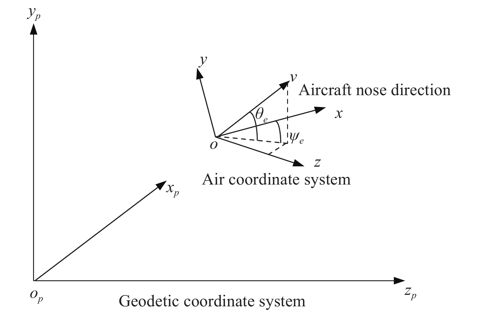
${{x}}_{0},{{y}}_{0},{{z}}_{0}$ ),同时定义红外诱饵弹出膛后的质量为${m}$ ,重力加速度为$g$ ,发射速度${{v}}_{{j}}$ 。假设红外诱饵发射器相对于载机的安装位置的中心点与载机坐标系的原点重合,安装方位由偏航角${\psi _e}$ 和俯仰角${\theta _e}$ 表示,即确定初始发射速度方向。偏航角的定义为红外诱饵发射器安装的方向与机体纵向机头方向之间的夹角,从载机尾部向头部看时红外诱饵发射器的偏航角逆时针方向为正。俯仰角的定义为红外诱饵发射器安装的方向与载机机体平面之间的夹角,俯仰角与载体机头上仰的方向一致时为正,如图7所示,${\theta _e}$ 为正,${\psi _e}$ 为负。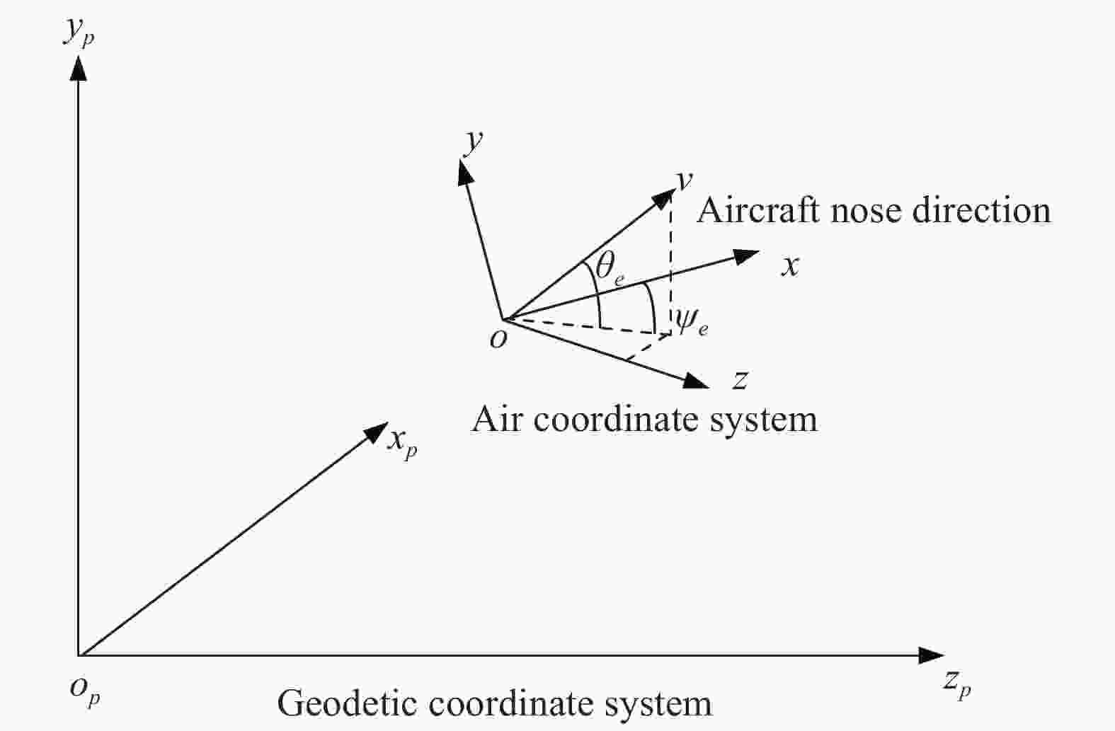
Figure 7. Coordinate diagram
计算红外诱饵出膛后的运动轨迹,具体过程如下:首先计算红外诱饵在大地坐标系下的初速度
${\left( {{v_{x00}},{v_{y00}},{v_{z00}}} \right)^{\rm T}}$ ,令红外诱饵弹出膛时刻在机体坐标系里的初速度分量分别为${\left( {{v_{x0}},{v_{y0}},{v_{z0}}} \right)^{\rm T}}$ ,即:机体坐标系到准大地坐标系的转换矩阵
${L_2}$ 为:偏航角:
$ {\psi _p}$ ,俯仰角为${\theta _p}$ ,滚转角:${\gamma _p}$ 即
红外诱饵在出趟后主要受阻力、重力等的影响,文中主要考虑阻力和重力,同时忽略风速对红外诱饵弹的影响。阻力是红外诱饵弹几何形状、速度、质量和大气密度的函数,用
$f$ 表示,同时定义$\alpha $ ,其为红外诱饵速度$v$ 在xoz平面的投影即:式中:
${C_d}$ 为阻力系数,与速度和几何体形状有关;$v$ 为红外诱饵弹的瞬时速度;$\;\rho $ 为大气密度;${A_{ref}}$ 为红外诱饵弹的迎风面积。同时在大地坐标系下,各个时刻红外诱饵在
${x}$ 轴、${y}$ 轴、${z}$ 轴方向上的速度分量${v_x}$ ,${v_y}$ ,${v_{\textit{z}}}$ 分别可以通过$m\dfrac{{{\rm d}{v_x}}}{{{\rm d}t}} = {f_x}$ ,$m\dfrac{{{\rm d}{v_y}}}{{{\rm d}t}} = - mg + {f_y}$ ,$m\dfrac{{{\rm d}{v_{\textit{z}}}}}{{{\rm d}t}} = {f_{\textit{z}}}$ 计算得到。即红外诱饵在大地坐标系下,各个时刻的速度为
${\left( {{v_x},{v_y},{v_{\textit{z}}}} \right)^{\rm T}}$ 。在具体计算时,红外诱饵运动轨迹时单步步长取为1 ms,即在每个仿真步长可认为是匀速运动,最后利用四阶龙格-库塔法[13-14],再与飞机的位置坐标合成,即可近似的计算出任意时刻
$t$ ,红外诱饵在大地坐标系里的位置坐标${\left( {x,y,z} \right)^{\rm T}}$ 。基于上述干扰轨迹生成理论,某飞机机动情况下干扰投放运动轨迹模拟如图8所示。

Figure 8. Motion simulation of single launch jamming in aircraft maneuvering
-
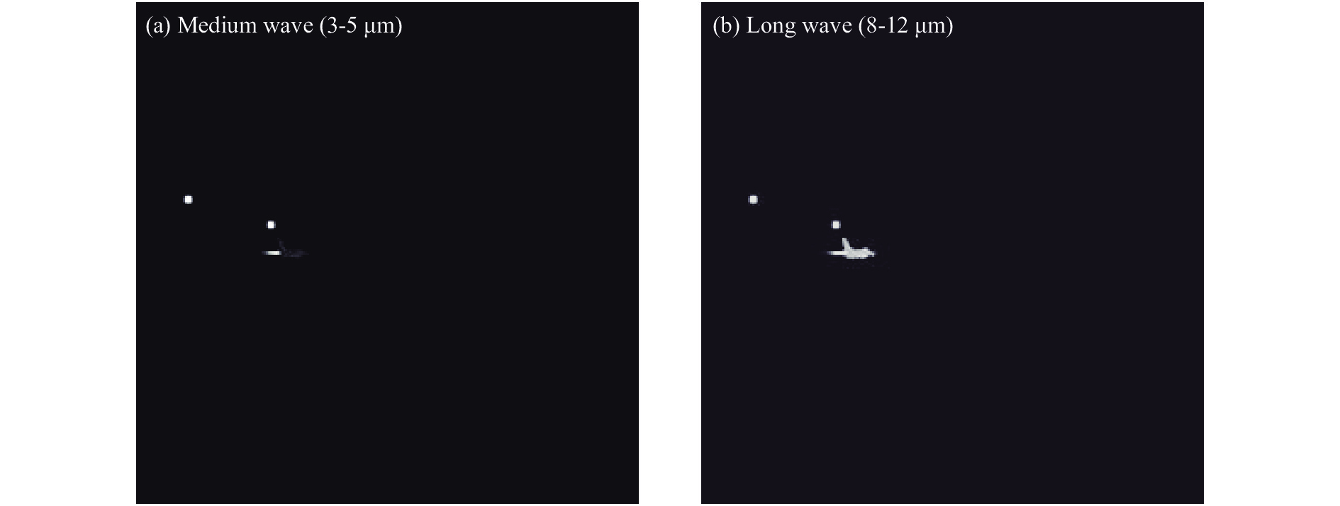
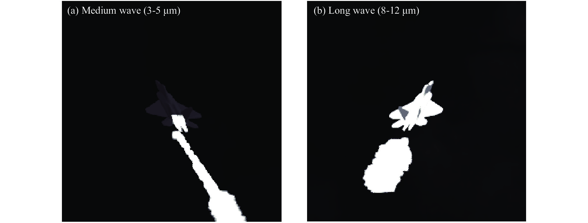
基于上述双色目标和干扰建模过程,使用某中长双色产品采集仿真图像验证效果,中长波产品,中波探测波段为3~5 μm,图像分辨率为320×256;长波探测波段为8~12 μm,图像分辨率为320×256。分别从远距侧向以及近距尾后干扰投放验证双色仿真效果,具体如图9、图10所示。
如图9、图10所示,远距情况下中长波战机机身对比较为明显,而到末端战机本身以外,红外诱饵燃烧尺寸特征区别也大,而中长红外成像特征的差异有助于在复杂对抗场景下识别目标。

Figure 9. Medium wave and long wave simulation of long range lateral jamming launch for aircraft

Figure 10. Medium wave and long wave simulation of short range tail jamming launch for aircraft
-
文中重点介绍了基于MOS电阻阵以及DMD场景模拟系统组成的中长波双色半实物仿真系统,在此基础上开展中长双色典型地物目标、空中目标及其红外诱饵的建模仿真。在抗干扰半实物仿真考核中,目标在不同机动方式、不同投放角度及速度下投放红外诱饵后,其运动轨迹的逼真度直接影响抗干扰评估结果,为此在红外诱饵运动模型建立过程中,考虑投放角度、速度尤其机动方式对红外诱饵运动轨迹的影响,提高模型模拟置信度。最后通过中长波产品完成中长双色半实物仿真,验证中长波双色在实际对抗过程中的成像差异。
Simulation technology of medium and long wave dual color target and jamming
doi: 10.3788/IRLA20210208
- Received Date: 2021-03-31
- Rev Recd Date: 2021-06-21
- Publish Date: 2022-04-07
Fund Project:
National Ministry Fund
-
Key words:
- MOS resistance arrays /
- DMD target simulator /
- hardware-in-the-loop simulation /
- infrared jamming
Abstract: In order to evaluate the anti-jamming performance of the medium and long wave infrared dual-color detecting system, the dual-color target and interference simulation technology were studied. Based on multi-band infrared targets and interference generation technology, the multi-band target and jamming spectral radiation model and motion model were established. At the same time, based on the medium and long wave dual-color hardware-in-the-loop simulation system, through the medium and long wave infrared image simulator composed of MOS resistance array and DMD target simulator, multi-channel compound directional optical system and missile target attitude simulation system with the detection system under test, the medium and long dual-color image generated by the target simulator was compounded, collimated and processed by multi-channel compound directional optical system. After beam expansion, it is provided to the dual-color detection system to verify the simulation effect.


 DownLoad: