


-
火炮身管、反后坐装置、发动机气缸等深孔类零件长径比大、内部空间狭小,难以集成高精度测量仪器,其内表面精密检测一直是加工制造业的难题[1]。近年来,结构光技术因其精度高,测量速度快,无损检测等优点[2]被广泛应用于深孔零件的三维测量中[3-4]。
为获取深孔零件内表面完整点云信息,需要检测系统在被测零件内部旋转整周,通过点云拼接实现内表面整环三维重建[5]。常用的点云拼接算法为迭代最近邻算法(ICP) [6],该种算法依托“最近邻点”之间的约束关系对变换矩阵进行迭代优化,能够实现精细点云拼接,但该算法依赖于拼接初值的选取。近年来,国内外许多学者通过标志点法[7-8],特征匹配法[9-10]和旋转台法[11]等不同方式[11-12]获取拼接初值。标志点法通过在被测物体上粘贴标志点,获取不同位姿下的转换矩阵对测量点云进行匹配,由于标志点法容易造成测量点云空洞,并且在较长的深孔零件内部受空间限制无法粘贴,在深孔测量中很难应用。特征点法通过寻求不同点云重叠区域的特征点实现点云配准,但在变化不明显的内表面中无法提取有效的特征点,给点云拼接带来了困难。基于旋转台的拼接方法通过旋转台标定确定被测物体或者测量系统空间运动的转换矩阵以提供拼接初值,在三维重建中有较大应用,但是对于复杂装配深孔零件的就地检测还需要更加简洁高效的拼接方法。
文中依托深孔零件内表面测量系统的单视角三维重构点云,力图实现内表面完整面形的三维重建。建立了检测系统的坐标转换模型,在该模型下提出了测量系统的位姿标定方法,并进行标定实验求解检测系统的位姿参数,通过精细点云拼接实现了深孔内表面三维重建。
-
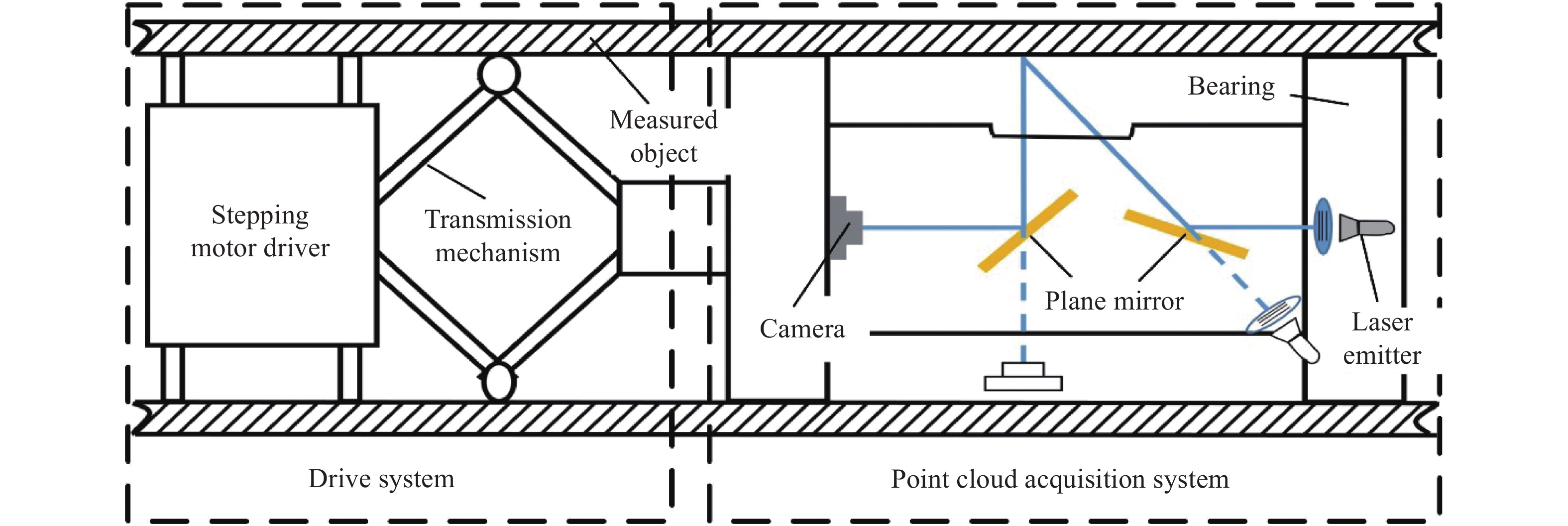
文中使用的深孔零件检测系统如图1所示,系统由驱动系统和点云采集系统组成。在进行测量时,CCD相机通过平面镜在深孔内表面上垂直成像,采集结构光发射器投射到深孔类零件内表面形成的多线结构光图像,生成表面点云。点云采集系统在测量时由步进电机牵引在被测零件中不断旋转,直至获取覆盖深孔类零件内表面的全部点云数据,测量系统的旋转角度由步进电机提供,最终通过点云拼接获取深孔零件内表面的完整点云。

Figure 1. Diagram of system working
系统所用相机型号为TXG03,分辨率为656×494 pixel,镜头型号为LM35JC10m,焦距为35 mm,结构光源采用BX-PT20V5半导体绿光激光光源透过结构光栅产生多线结构光,驱动点云采集系统旋转的步进电机步距角为0.1º。
-
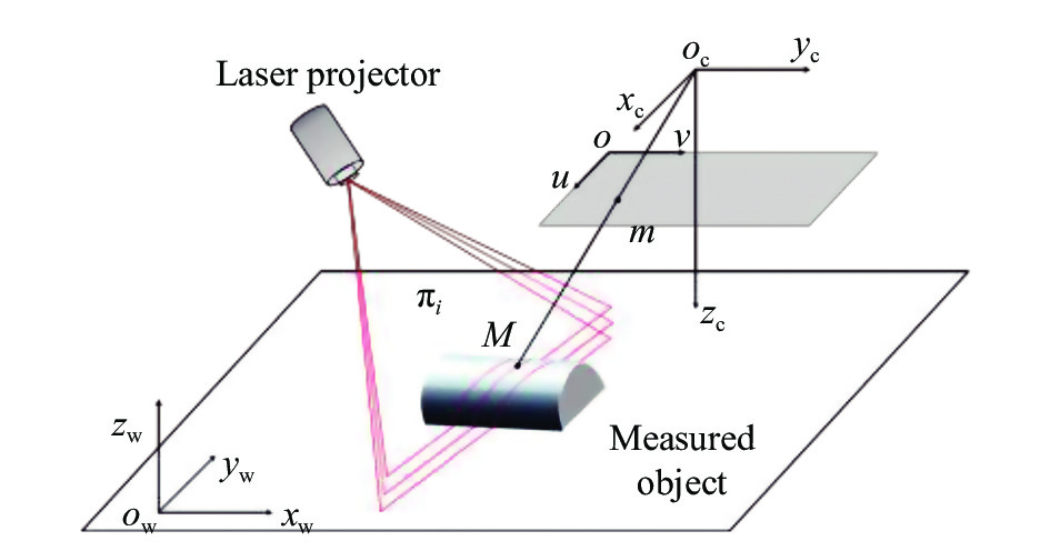
文中使用的点云采集系统为多线结构光系统,其检测原理如图2所示,其中
$o - {x_{\rm{c}}}{y_{\rm{c}}}{{\textit{z}}_{\rm{c}}}$ 为相机坐标系,$o - {x_{\rm{w}}}{y_{\rm{w}}}{{\textit{z}}_{\rm{w}}}$ 为世界坐标系,$o - uv$ 为像素坐标系。
Figure 2. Multi-line structured light measurement principle
设世界坐标系中一被测点M~ (xw, yw, zw)T,其在图像坐标系中的对应点为m ~ (u, v)T,它们对应的齐次表示为
$\widetilde M$ ~ (xw, yw, zw, 1)T,$ \widetilde m $ ~ (u, v, 1)T。根据针孔相机模型有[13]:式中:s为固定参数;K 为相机内部矩阵;[R, t]为世界坐标到相机坐标的旋转平移矩阵。在多线结构光系统中,点M同时为光平面πi (i=1, 2, ···, n, n为光平面的数量)上一点,光平面在世界坐标系中的方程为:
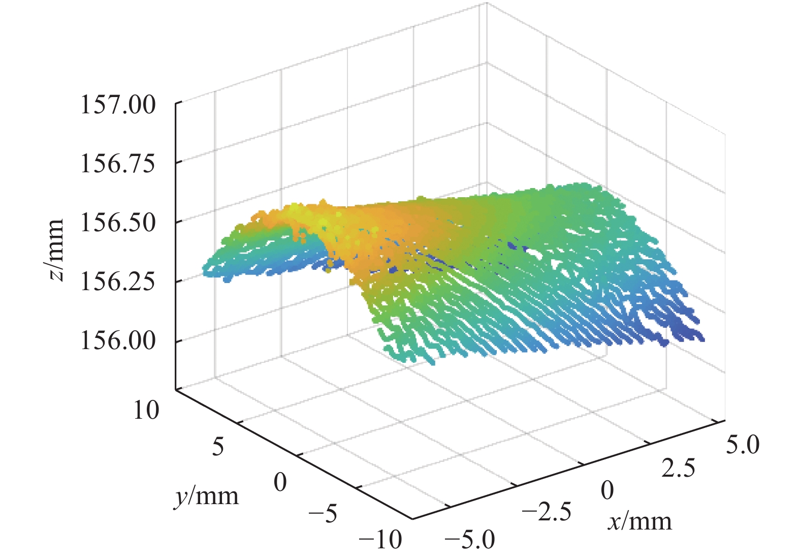
式中:Ai, Bi, Ci, Di为光平面πi参数。将相机坐标系建立在世界坐标系上,联立公式(1)、(2),解算所有光平面上的点,可以得到被测物体表面在相机坐标系中的测量点云[14]。系统在直圆筒中的测试点云如图3所示。

Figure 3. Point cloud of the smooth cylinder region
-
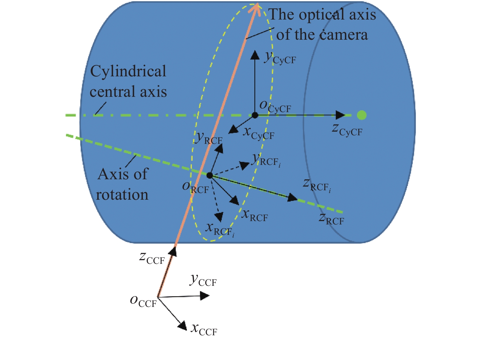
在理想的设计模型中,旋转轴与深孔内表面中心轴重合,相机光轴经反光镜作用与旋转轴相互垂直。由于装配误差存在,实际系统测量的空间位置如图4所示,旋转轴、深孔中心轴与相机光轴在测量系统中实际为一般位置的空间直线,均不在同一平面上。在测量过程中,文中作如下假设:

Figure 4. Coordinate transformation model
(1)相机光轴与旋转轴之间的位置关系由装配关系决定,检测系统装配之后的相对位置关系不变,因此在测量过程中相机光轴与旋转轴之间的位置关系固定不变;
(2)在旋转测量过程中,旋转轴线与深孔类零件内表面轴线位置误差是由轴承与被测零件之间间隙造成,在实际测量过程中轴承间隙往往在固定的一侧,忽略在旋转过程中的跳动误差,测量时旋转轴和深孔类零件的中心轴的位置固定不变。
基于以上假设,建立图4所示坐标系:
$o - {x_{{\rm{CCF}}}}{y_{{\rm{CCF}}}}{{\textit{z}}_{{\rm{CCF}}}}$ :相机坐标系(CCF),坐标原点在镜头中心,z轴为相机光轴,固定在相机上。$o - {x_{{\rm{RC}}{{\rm{F}}_i}}}{y_{{\rm{RC}}{{\rm{F}}_i}}}{{\textit{z}}_{{\rm{RC}}{{\rm{F}}_i}}}$ :点云旋转坐标系(RCFi),原点建立在旋转轴上某个定点,在旋转测量过程中与CCF拥有固定的位置关系,其z轴与旋转轴重合,空间位置随系统测量姿态旋转变化,i为不同测量位置的点云旋转坐标系。$o - {x_{{\rm{RCF}}}}{y_{{\rm{RCF}}}}{{\textit{z}}_{{\rm{RCF}}}}$ :全局旋转坐标系(RCF),原点建立在RCFi原点上,z轴与旋转轴重合,与RCFi存在固定的旋转关系,在旋转测量过程中空间位置固定不变。$o - {x_{{\rm{CyCF}}}}{y_{{\rm{CyCF}}}}{{\textit{z}}_{{\rm{CyCF}}}}$ :全局圆柱坐标系(CyCF),原点建立在深孔类零件内表面中心轴线上一定点,其z轴与身管中心轴线重合,在旋转测量过程中空间位置固定不变。为了完成测量点云的整环拼接,在相机测量过程中将整体坐标系建立在CyCF上,将不同角度获取的点云数据转换到CyCF上完成身管轴线的三维重建,测量过程中的转换过程为CCF → RCFi → RCF → CyCF。坐标系之间的转换关系分别为:
通过公式(3)、(4)、(5)可得:
式中:R1, R2, T1, T2为固定参数的旋转位移矩阵;r11, r12, ···, r19为R1, R2内的参数;t21, t22, ···, t29为T1,T2内的参数,在进行整环测量时需要对这些参数进行标定求解;θ为系统的旋转角度,在实际测量中可以通过高精度的步进电机控制得到。在实际坐标转换过程中,R1, R2, T1, T2中参数的数值大小与系统装配关系有关,在检测系统不变的情况下为固定值,公式(6)化为:
式中:ti(θ)=aisin(θ)+bicos(θ)+ci,i=1, 2, ···, 12为CCF→CyCF的旋转平移矩阵的内部参数;ai, bi, ci为与CCF→RCFi和RCF→CyCF有关的旋转平移参数运算而来的系统位姿参数。在获取系统位姿参数后,便可以通过步进电机的旋转角度在公式(7)下完成深孔类零件多视角下的点云拼接。
-
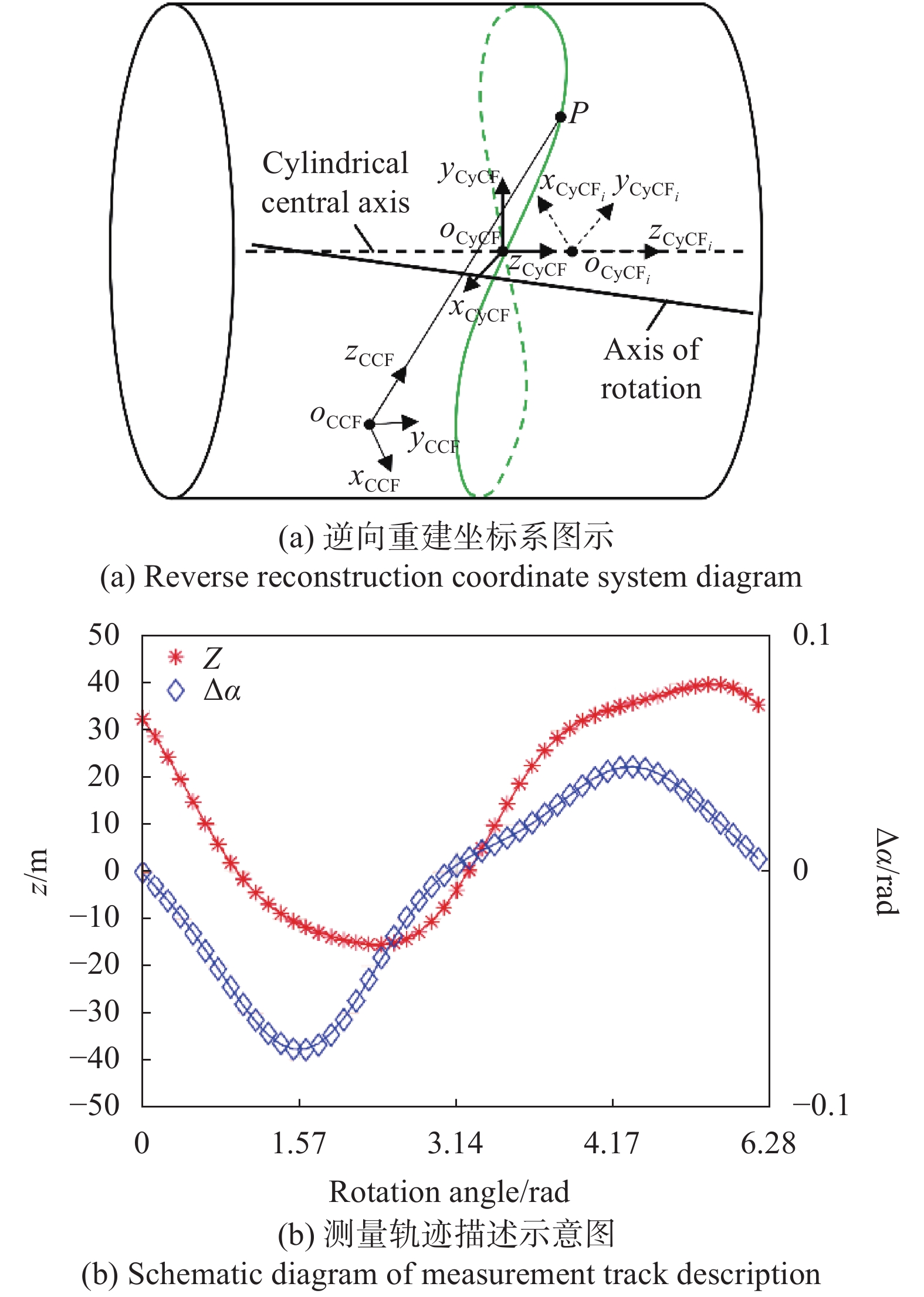
实际测量得到的CCF点云由于装配误差存在,如图3所示测量直圆筒点云,点云轮廓的不同倾斜程度反映了不同的测量位置。对CCF中的点云进行圆柱拟合,依托拟合的圆柱方程建立点云圆柱坐标系(CyCFi),其空间位置如图5 (a)所示,CyCFi原点为相机光轴与测量点云交点在深孔类零件内表面中心轴线上的投影点,z轴与CyCF的z轴重合,为测量深孔内表面的中心轴线,因此不同位置的CyCFi与CyCF之间仅存在z轴上的位移和旋转变换关系,通过圆柱拟合求测量点云在CyCFi中的坐标可以重建不同位置的测量点云在CyCF中的位置。

Figure 5. Reverse reconstruction model
如图5 (a)所示,旋转测量时相机光轴在深孔内表面的测量轨迹实际为不同轴的单叶双曲面和圆柱的交线,其轨迹与系统位姿参数有关[14]。测量轨迹上一点对应的CyCFi在CyCF中的位置随系统旋转角度θ不断变化,CyCFi与CyCF之间在z轴上的位移
$\Delta {\textit{z}} = \left| {{o_{\rm CyCF}}{o_{{\rm CyC}{{\rm F}_i}}}} \right|$ 和旋转角α与系统旋转角度θ之间存在一定的函数关系。旋转轴与深孔中心轴相对位置不变,旋转一周后测量点重新回到起始位置,为关于θ的周期变化函数。为准确描述测量轨迹,设被测内表面为中心轴为z轴,直径为155 mm的圆柱,旋转轴为过定点(10,0,0),方向为(−0.1231, 0.1231, 0.9847)T的空间直线,初始位置的光轴为过定点(40,15,15),方向为(0.9513, 0.2643, 0.1586)T的空间直线,旋转测量中由测量轨迹确定的CyCFi与CyCF之间的相对位移Δz和角度差值Δα=α−θ在等间隔的旋转角度在50个点的分布如图5(b) 所示,对测量点进行傅里叶级数拟合,当拟合阶数为3时,拟合的曲线能够大致符合测量的形状,拟合的RMSE分别为0.1427, 3.9×10⁻⁴。将CyCF建立在旋转测量时所有CyCFi的起始位置时,设位置变换参数关系为:
式中:Pk,Qk,pk,qk为固定参数,数值大小与测量系统旋转轴和被测内表面中心轴的空间位置有关。因此,测量系统在不同的旋转角度下得出CyCFi与CyCF的转换关系可描述为:
参数Pk,Qk,pk,qk, k=1, 2, 3为逆向重建模型中的未知量,当重建参数符合测量系统位姿实际情况时,可以确定不同旋转角度的点云在全局圆柱坐标系中的位置。
-
在坐标转换模型中,ti(θ)的系统位姿参数ai, bi, ci在旋转测量过程中不发生变化,系统位姿参数被确定之后,在测量过程中通过步进电机旋转的角度可以将从不同检测位置的CCF点云转换到CyCF中,实现高精度点云拼接。
为求取系统位姿参数,结合点云逆向重建,通过公式(7)、(10)可以得到:
CCF点云数据在CyCFi中的坐标在2.2节中求出,为求得系统位姿参数ai, bi, ci, 实验过程中旋转n次采集光滑圆筒内壁的点云数据,通过SDV分解求出在不同角度测量位置的转换矩阵,转换矩阵的值随测量角度θ变化,最少需要3个不同角度测量位置的变换方程才能求解出系统位姿参数。为确保点云覆盖圆筒整环,使用最优化算法通过式进行参数求解。其中Pk,Qk,pk,qk为变量,利用优化算法求解ti(θ)中的系统位姿参数,在不同角度的测量过程中,系统位姿参数固定不变,因此设代价函数为:
式中:tji为第i组点云数据求取的tj,
${\widehat t_j}$ 为通过最小二乘求解出ai,bi,ci的期望值。在优化计算过程中,不同的重建参数求出的系统位姿参数的变化值不同,当代价函数趋于最小时,系统位姿参数趋于稳定,与检测系统的位姿参数接近,将此时的ai, bi, ci值作为最终的标定结果,完成系统测量位姿参数标定。在点云拼接过程中,测量系统通过不同测量姿态的θ实现点云拼接。 -
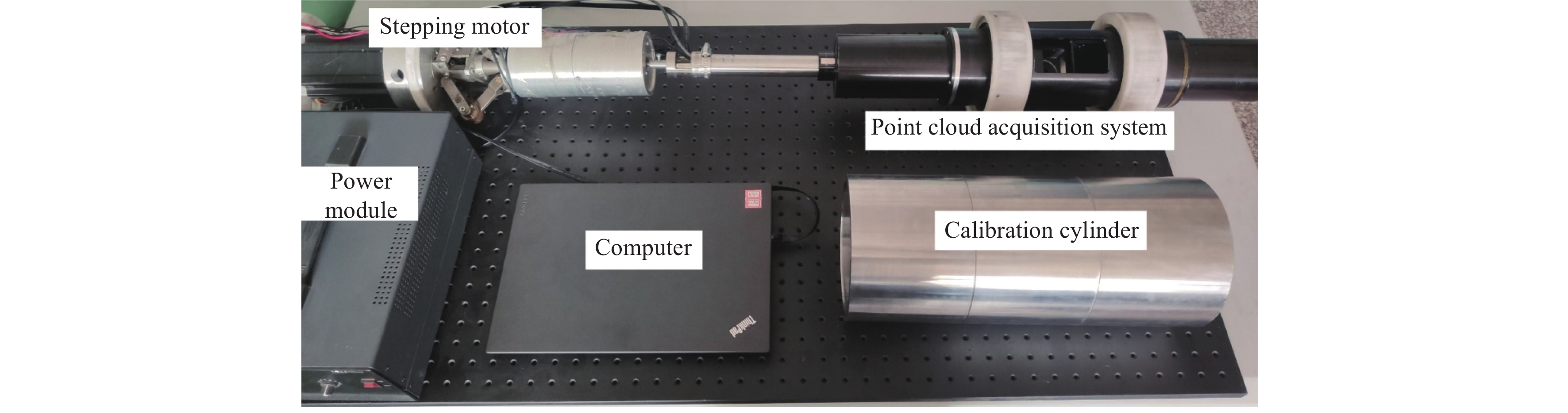
文中搭建系统如图6所示,标定实验中使用精密加工的304不锈钢标定筒,内径155 mm,外径175 mm,加工精度为0.02 mm,内表面粗糙度Ra为0.4 μm。

Figure 6. Experimental setup
-
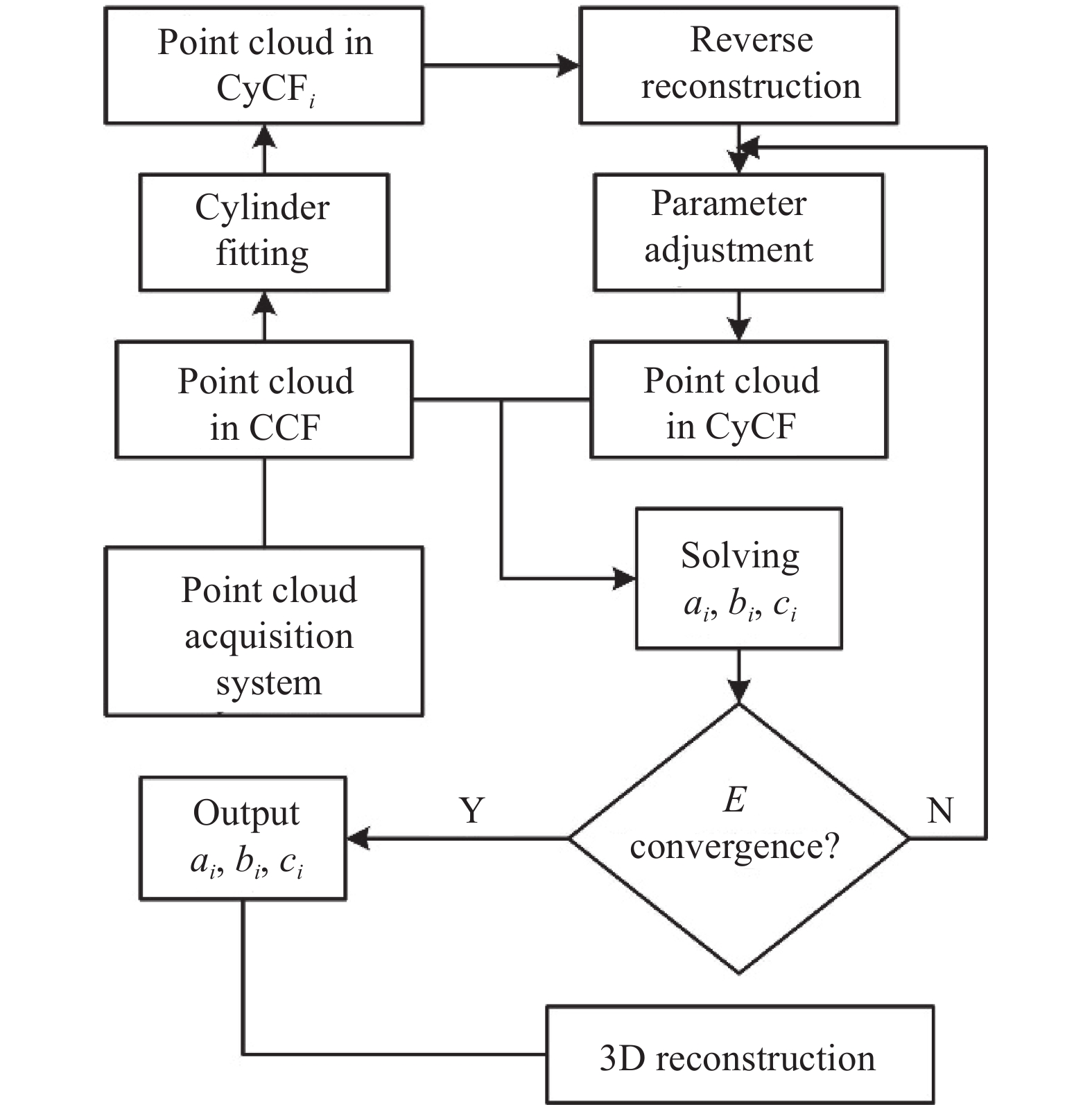
为验证文中算法,使用标定筒对检测系统位姿进行标定时。标定步骤如图7所示。首先以固定步长旋转深孔类零件测量系统,对固定内径的直圆筒进行三维重构,由点云采集系统获取不同角度测量区域在CCF中的单视角点云;然后,对CCF中的点云进行圆柱拟合,求取CCF中z轴与柱面交点在柱面中心轴线的投影点作为CyCFi的原点,将点云通过坐标变换转换到CyCFi中;然后,结合逆向重建模型建立CyCFi→CyCF中的坐标转换关系,并通过CCF点云坐标和CyCF中的点云坐标关系求解系统位姿参数,在求解过程中不断调整逆向重建参数,求取损失函数接近最小值收敛时的系统位姿参数。最后,在实际测量中通过标定的系统位姿参数对不同位置的测量点云进行点云拼接,完成深孔的三维重建。

Figure 7. Calibration experiment process
在标定实验中,为提高重建误差模型参数的拟合精度,尽量密集得采集深孔内表面点云,以8º为步长采集标定筒内表面的点云数据,增加重叠区域。按照上述步骤进行系统位姿参数标定实验,标定结果如表1所示。
t1(θ) t2(θ) t3(θ) a1 b1 c1 a2 b2 c2 a3 b3 c3 0.0014 0.0250 0.0062 0.9996 0.0078 0.0024 −0.0078 0.9993 0 t4(θ) t5(θ) t6(θ) a4 b4 c4 a5 b5 c5 a6 b6 c6 1.2186 −79.1166 −0.0280 0.0386 −0.0038 −0.0013 0.0078 −0.9986 0 t7(θ) t8(θ) t9(θ) a7 b7 c7 a8 b8 c8 a9 b9 c9 0.9997 0.0079 0.0025 −79.1178 −1.2321 −0.1902 0 0 0.9986 t10(θ) t11(θ) t12(θ) a10 b10 c10 a11 b11 c11 a12 b12 c12 −0.0145 −0.0020 −0.0029 0 0.0020 −0.0318 −4.7672 −5.9891 4.9857 Table 1. The calibration results of the system pose parameters
-
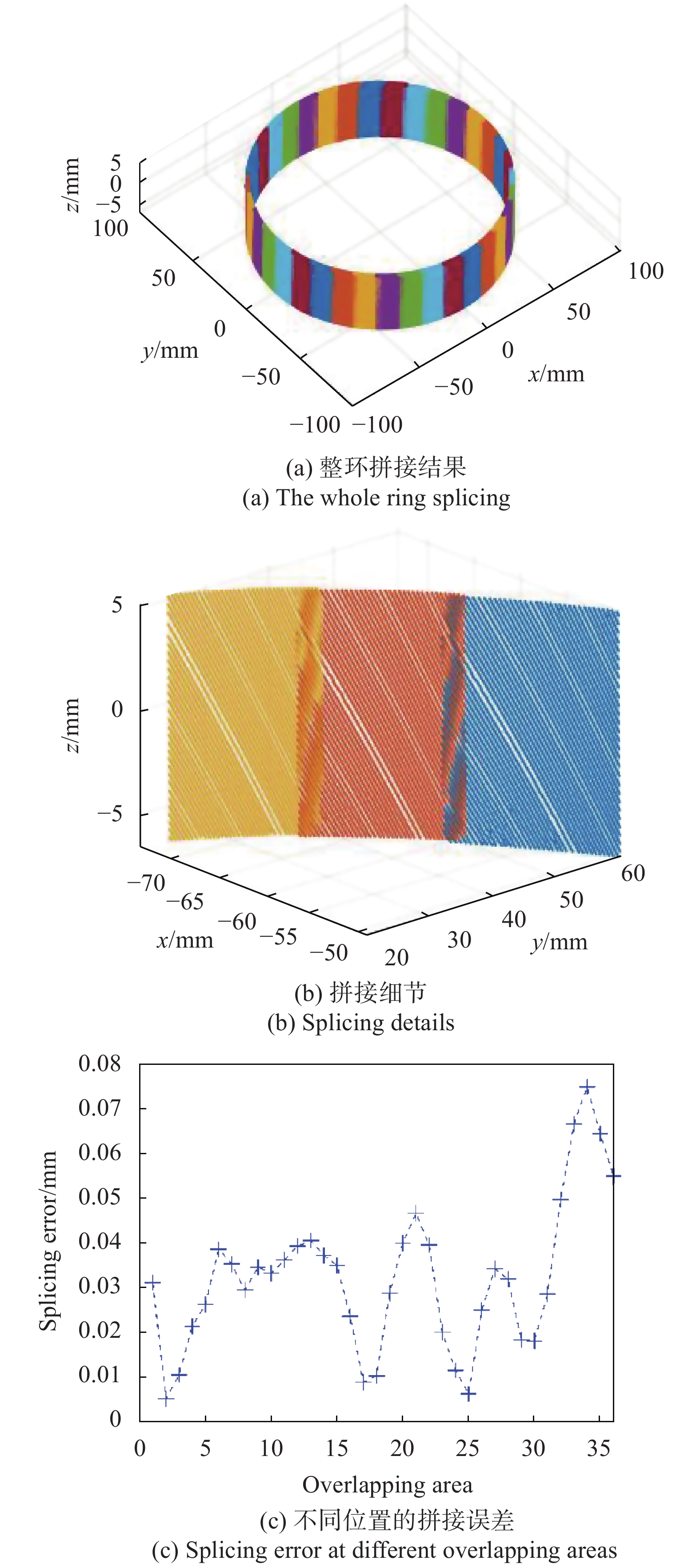
为评估文中点云拼接方法的性能,使用表1中的标定数据对标定筒内表面进行独立的测量实验,在精度评估实验中,每10º采集标定筒其他区域的内表面点云数据进行拼接,其拼接结果及细节如图8 (a)、(b)所示。将两片点云重叠区域到全局坐标系z轴的径向距离差值作为拼接误差,对点云拼接的重叠区域拼接误差计算结果如图8 (c)所示。由图8 (c)可知,在155 mm直径的深孔类零件测量条件下,点云拼接的多数重叠区域拼接误差要低于0.05 mm,最大误差在0.08 mm以下,说明文中提出算法有效,拼接精度满足实际要求。将拼接的点云结果向xoy平面投影,拟合平面圆周求取测量直圆筒的直径为154.957 mm,能够对深孔内表面的关键参数提取的精度要求。参考文献[11]测量圆柱内径的点云拼接精度为0. 12 mm,参考文献[15]在测量拼接60 mm直径圆柱点云时重叠误差在0.05 mm以下,文中提出的拼接方法精度与之相比均有明显优势。

Figure 8. Result of the point cloud splicing
-
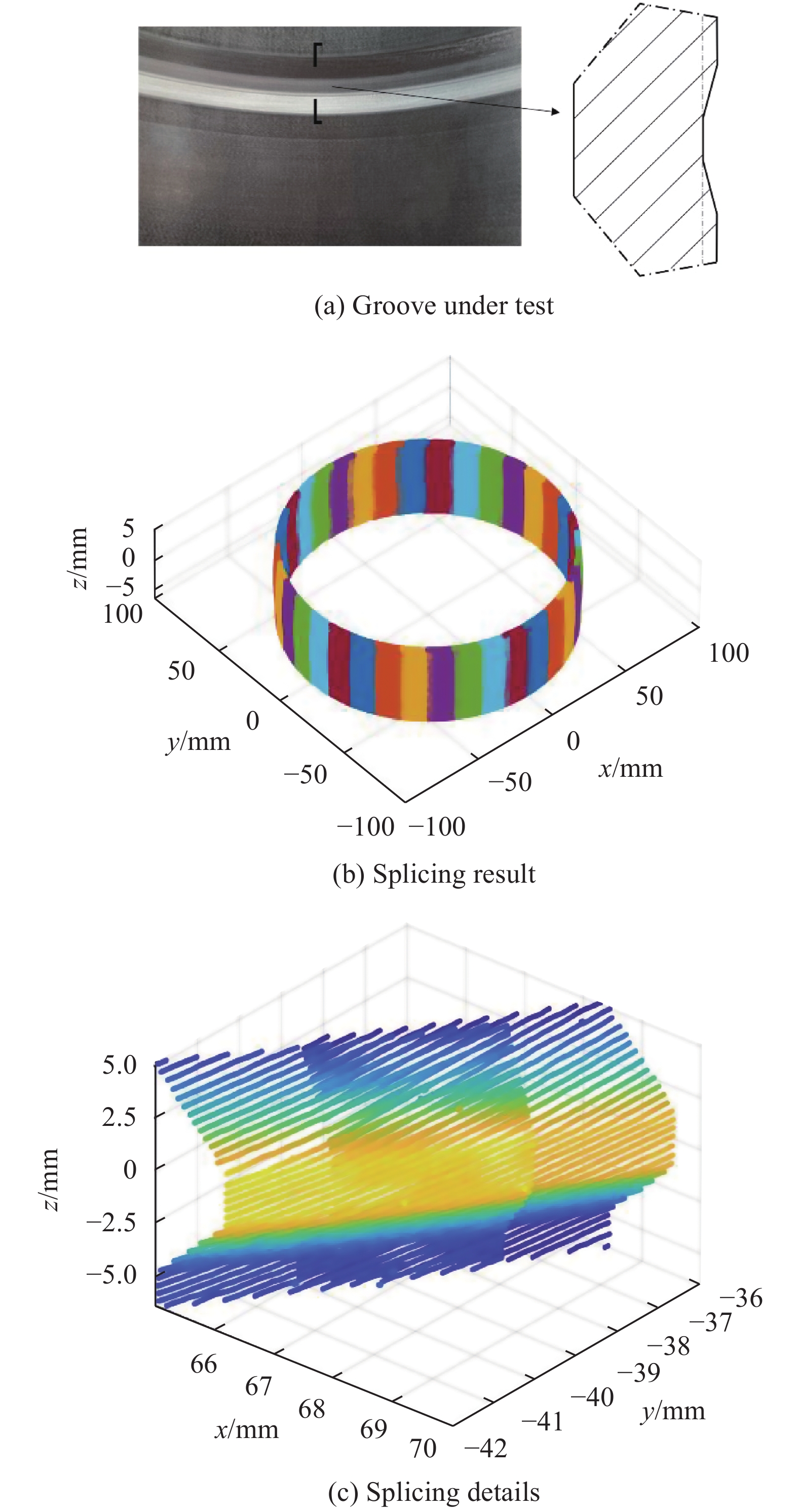
对实际零件进行实验验证,使用深孔类零件内表面检测系统对图9 (a)所示带有凹槽的深孔类零件进行测量,在实验过程中同样以10º为步长旋转采集点云数据。对凹槽部分进行点云拼接实验,重建结果及细节如图 9(b)所示,拼接重叠处过渡光滑,拼接精度满足需求。

Figure 9. Splicing results of groove regions
-
文中基于深孔类零件检测场景,通过对旋转轴和深孔类零件中心轴的位置分析建立了深孔类零件点云拼接数学模型,并提出了该种转换模型的标定方法,解决了在深孔类零件内表面检测中的点云拼接问题。该方法仅利用旋转机构旋转的角度便能够实现点云的高精度拼接,鲁棒性好,能够为ICP算法提供准确、稳定的初值。与传统的粗拼接方法相比,不需要粘贴标志点和特征匹配就能实现较高精度的点云拼接,能够应用到一般的深孔类零件内表面检测系统中。同时文中提出的坐标转换模型以测量系统的一般空间位置为基础,对系统安装位置要求少,对深孔零件检测装置的安装位置具有较强的适用性。最后通过实验证明,文中算法的拼接误差不大于0.08 mm。
Research on point cloud splicing for inner surface inspection of deep hole
doi: 10.3788/IRLA20210210
- Received Date: 2021-03-31
- Rev Recd Date: 2021-07-21
- Publish Date: 2021-12-31
-
Key words:
- optical measurement /
- three-dimensional reconstruction /
- coordinate transformation /
- deep hole inspection
Abstract: The single-view point cloud obtained by the deep hole inner surface inspection system cannot reflect the full picture of the inner surface of the deep hole part. In order to realize the three-dimensional reconstruction of the complete surface shape of the deep hole inner surface, a pose calibration technology for the deep hole inner surface inspection system was proposed, which was used to provide the initial value of the point cloud stitching for the reconstruction of the inner surface of the deep hole. Firstly, the principle of deep hole inner surface detection technology was introduced, the coordinate transformation model of deep hole parts measurement point cloud was analyzed and established, the system pose parameters that need to be calibrated in the coordinate transformation model were determined; Then, the measurement trajectory of the system was described by the rotation axis angle, and the point cloud was reconstructed inversely; Then the measurement trajectory model was optimized with the solution error of the system parameter as the loss function, and the system pose parameter calibration was realized; Finally, point cloud splicing experiments of the straight cylinder and the concave groove show that the method was suitable for the detection of the inner surface of the deep hole and easy to operate, the splicing error was not more than 0.08 mm. Compared with other methods, it has certain advantages.


 DownLoad: