


-
基于视觉图像的位姿测量[1-3]技术具有结构简单、非接触、测量精度高、稳定性好等优点,因此被广泛应用于工业机器人对准技术[4],机器人手眼标定[5],组合位姿测量[6]等领域。基于视觉图像的位姿测量问题也被称为n点透视投影问题(PnP问题),即在摄像机模型内参数已知的情况下,通过三维空间点的世界坐标和图像坐标求解物体相对摄像机坐标系的位姿信息。
常用的位姿测量方法主要有非线性算法和线性算法两类。非线性算法在约束条件下建立目标函数,采用最小二乘法、Levenberg-Marquard等方法迭代求解物体位姿。非线性算法求解精度高,正交迭代算法(LHM算法)[7]是非线性算法中的代表性方法,通过最小化物空间共线性误差来构造目标函数,充分利用了透视投影模型的结构特点,保证了算法迭代过程中旋转矩阵的正交性。非线性算法求解时通常需要一个良好的初值才能全局收敛,对初值的选取比较敏感,如果选择不合理,计算时会增加迭代的次数,同时由于迭代产生的结果并不是封闭解,在初值精度较低的情况下会出现局部收敛,全局不收敛的情况,最终将导致不能求解得到精确的位姿信息。
线性算法计算量较小并且速度快,比非线性算法效率高。线性算法中的代表性方法包括DLS算法[8]、EPnP算法[9]、DLT算法[10]等。但是线性算法也存在一些局限性,对图像处理的要求比较高,如果定位特征点图像坐标提取不够精确,会导致位姿测量精度降低[11]。因此在线性位姿测量时,获取高质量的图像,图像处理后获取足够数量的有效定位特征点非常关键。在自然光条件下,摄像机采集定位特征点图像时,图像中通常存在高亮度区域(高灰度值区域)[12]。这些高亮度区域导致图像的纹理信息丢失,对图像处理产生影响,导致定位特征点图像坐标提取不准确,使参与运算的有效定位特征点数量减少,最终导致线性位姿测量精度降低。研究表明,可以通过在相机镜头前加装偏振片[13-14]并调整偏振片角度,从而减少高亮度区域,改善成像质量,提高视觉图像类测量方法的测量精度[15-16]。Zhu等[17]通过在镜头前添加偏振片,并根据靶标图像灰度值调整适宜的偏振片角度,提高了摄像机标定的精度。
综上所述,文中提出了一种基于最佳偏振角的线性位姿测量方法。在相机镜头前加装线偏振片,根据Stokes矢量建立偏振片最佳偏振角度求解模型,在最佳偏振角条件下,采集被测物体图像,减少高亮度区域,精确提取定位特征点图像坐标;建立被测物体位姿线性求解模型,计算被测物体位姿;进行了角点提取实验以及测量精度验证实验,实验结果表明,该方法能够有效减少图像中的高亮度区域,使参与位姿求解的有效定位特征点数量增加,提高了线性位姿测量精度,满足现代工业生产中位姿测量的要求。
-
文中研究在相机镜头前加装线偏振片,并建立最佳偏振角求解模型,在使用最佳偏振角的前提下采集定位特征点图像,减少高亮度区域对图像处理的影响,便于后续进行位姿测量。
光波具有偏振特性,Stokes矢量可用来表示光的偏振态。Stokes矢量S包含四个Stokes参数:S0, S1, S2, S3,如公式(1)所示,S0表示由成像系统接收的总光强,为x方向和y方向的光强和,S1表示在x方向和y方向的光强差,S2表示+45°方向与-45°方向的光强差,S3表示左旋圆偏振光分量与右旋圆偏振光分量的光强差。Ex, Ey表示光的电矢量E在x方向和y方向的振幅,α表示两者的相位差。
I(0°, 0°), I(45°, 0°)和I(90°, 0°)表示光在0°, 45°和90°三个不同角度的光强,由于光中圆偏振分量非常小,一般可以忽略不计,所以S3=0,Stokes矢量可以进一步表示为公式(2):
穆勒矩阵是用来描述偏振片作用的矩阵。使用M表示穆勒矩阵,M11···M44表示穆勒矩阵的16个参数,如公式(3)所示:
如图1所示,θ表示偏振片角度,穆勒矩阵M可以表示为公式(4),当偏振片角度发生变化时,穆勒矩阵亦会随之发生变化。
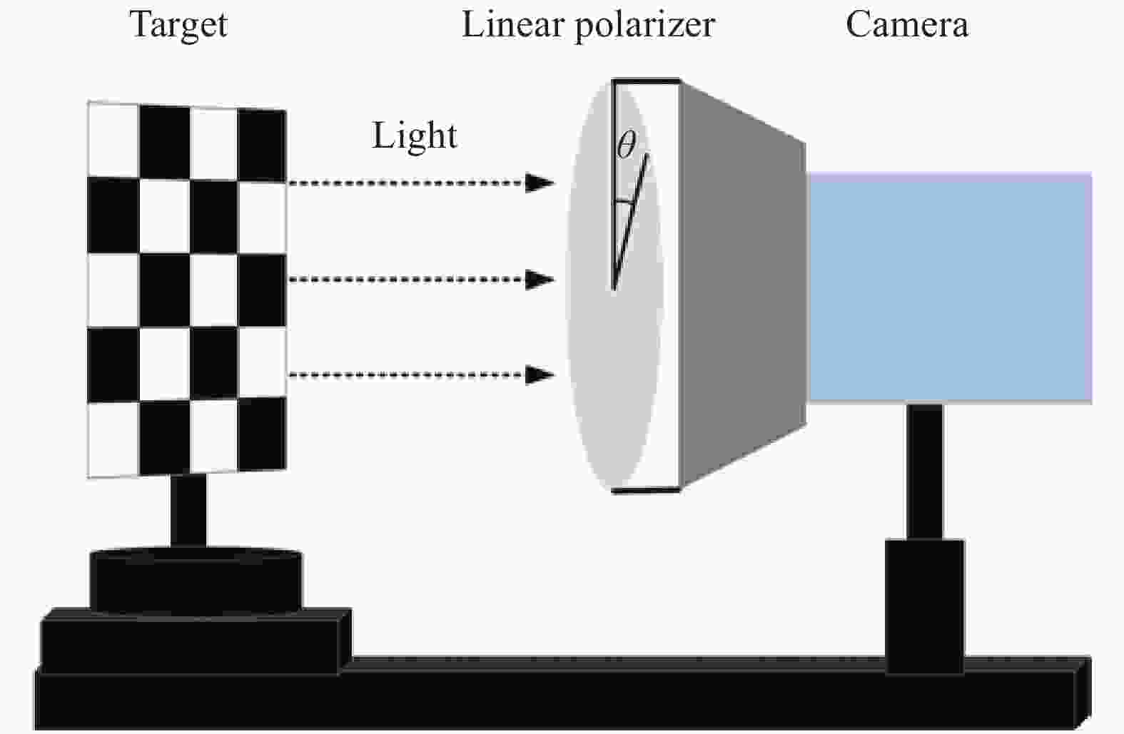
Figure 1. Schematic diagram of polarizer angle
用Sin表示入射光的Stokes矢量,Sout表示经过偏振片后的出射光的Stokes矢量,由于偏振片的作用,出射光的Stokes矢量和入射光的Stokes矢量之间的关系可以用公式(5)来表示。
出射光光强的表达式如公式(6)所示:
最终可以得到最佳偏振角度θopt的表达式如公式(7)所示:
-
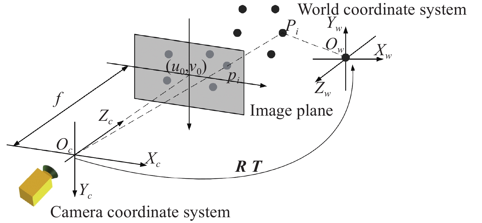
通过摄像机标定得出了摄像机模型内参数,即可以进行物体位姿的求解。如图2所示,Pi是空间的任意点,在图像平面上与之对应的点是pi。空间点在世界坐标系下的坐标是(Xwi, Ywi, Zw),转换到摄像机坐标系下坐标为(Xci, Yci, Zci),旋转矩阵为R3×3,平移向量为T3×1,在图像坐标系下的理想像素坐标为(u, v)。由于文中使用共面定位特征点阵列,所以Zwi=0。由理想图像像素坐标[ui, vi]可以计算出图像坐标[xi, yi]。

Figure 2. Pose measurement model
已知n组定位特征点的世界坐标[Xwi, Ywi, 0]和相应的图像坐标[xi, yi],构造矩阵A,每行ai为公式(8),共计n行。
设μ=[μ1, μ2, μ3, μ4, μ5],旋转参数r11, r12, r21, r22与平移参数tx, ty之比构成μ的各个元素:μ1=r11/ty, μ2=r12/ty, μ3=r21/ty, μ4=r21/ty, μ5=tx/ty。
设向量b=[x1, x2, x3, …, xn]包含了n组定位特征点的图像横坐标xi。因为A和b是已知的,根据公式(9)能解出未知的参数向量μ。
根据μ计算旋转参数和平移参数。设U=μ12+μ22+μ32+μ42,如公式(10)所示计算ty2。
设ty=(ty2)1/2,然后根据μ计算4个旋转参数r11=μ1ty, r12=μ2ty,r21=μ3ty, r22=μ4ty和平移参数tx=μ5ty。
为了确定ty的符号,选择一个定位特征点P,其世界坐标为[Xw, Yw, 0],所对应的图像坐标[x, y]远离图像中心,根据公式(11)计算ξx和ξy。如果ξx与x的符号一致且ξy与y的符号一致,则ty的符号正确,否则就要改变符号。
其余的旋转参数可根据公式(12)进行计算。
计算平移参数tz。首先构造矩阵A',矩阵的每一行如公式(13)所示:
构造向量b',每一项如公式(14)所示:
求解如公式(15)所示的线性方程组,其中v=(f, tz)T,f为焦距,最终得到tz的值。
-
位姿测量实验系统包括支架,相机,电控旋转平移台、线偏振片和位姿测量靶标,如图3所示。所有实验在密闭室内环境下进行,保持屋内光源位置及光强恒定。

Figure 3. Experimental system of pose measurement
实验中使用棋盘靶标,棋盘格尺寸为25 mm×25 mm。实验中的图像采集设备为海康威视MV-CA016-10UM相机,分辨率为1440×1080,像元尺寸为3.45 μm×3.45 μm,相机标定结果如表1所示。
文中的实验包括两部分:角点提取实验和测量精度验证实验。
Focal length fx =3425.60506 fy =3426.03573 Principal point Cx =732.2264 Cy =496.46005 Radial distortion k1=−0.0855 k2 =0.8394 k3 =−9.7639 Tangential distortion p1 =0.00023224 p2 =0.00023113 Table 1. Camera calibration experiment results
-
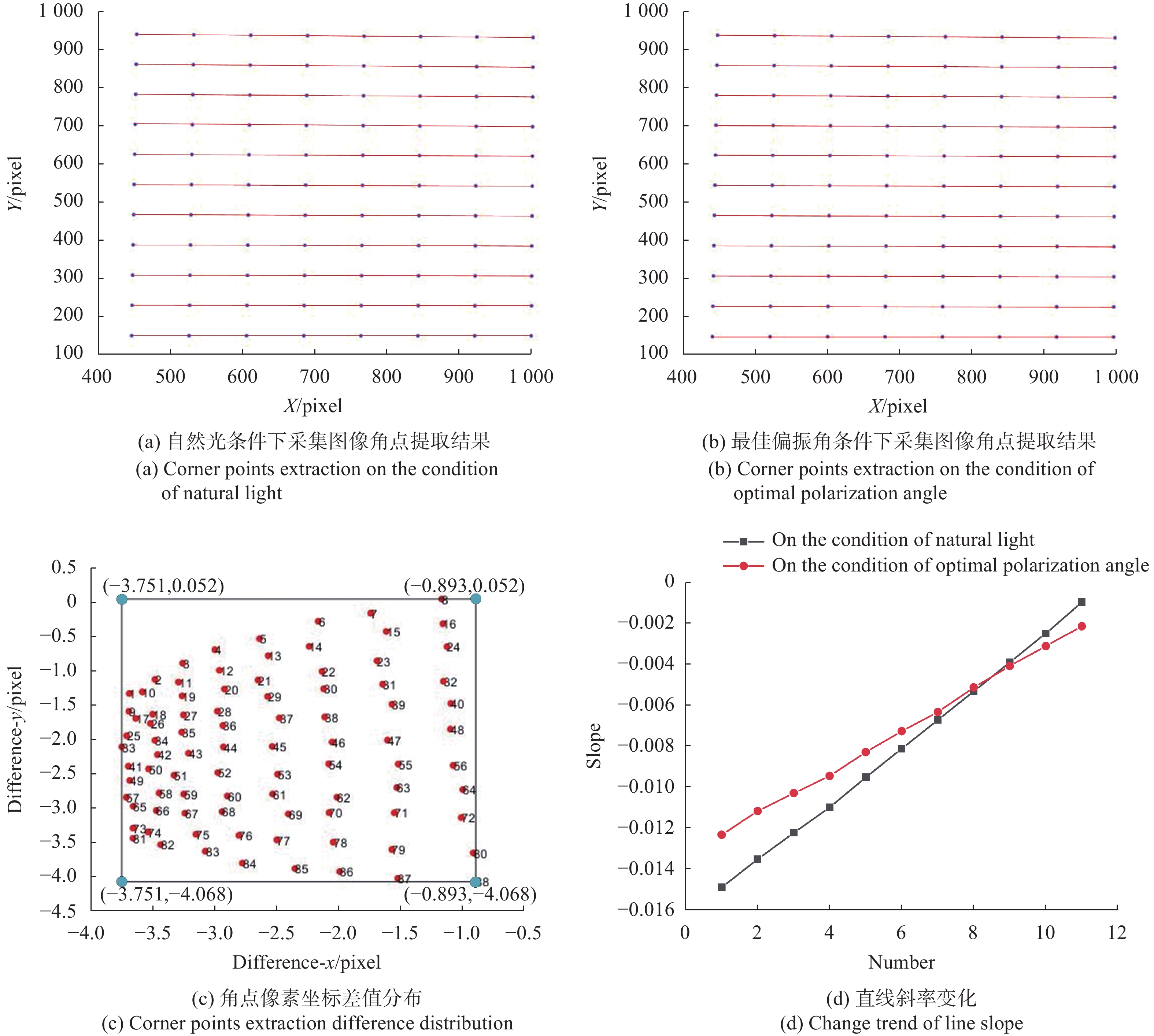
将靶标置于相机镜头前,近似平行于相机成像面,分别在偏振角0°、偏振角45°、偏振角90°的条件下,采集靶标图像,根据公式(7)完成最佳偏振角求解。在自然光(不加偏振片)条件下和最佳偏振角条件下分别采集靶标图像,共计2幅图像,使用相同的角点提取算法,提取出来11×8的角点阵列,角点分布如图4(a)和(b)所示,两幅图像对应的角点在x方向和y方向上的像素坐标差值分布如图4(c)所示,x方向上的像素坐标差值在[−3.751,−0.893]范围内,y方向上的像素坐标差值在[−4.068,0.052]范围内。可以看出,在最佳偏振角条件下采集的棋盘图像提取的角点坐标与自然光条件下采集的棋盘图像提取的角点坐标相差约2个像素,证明了在最佳偏振角条件下的图像角点坐标不同于自然光条件下的图像角点坐标。
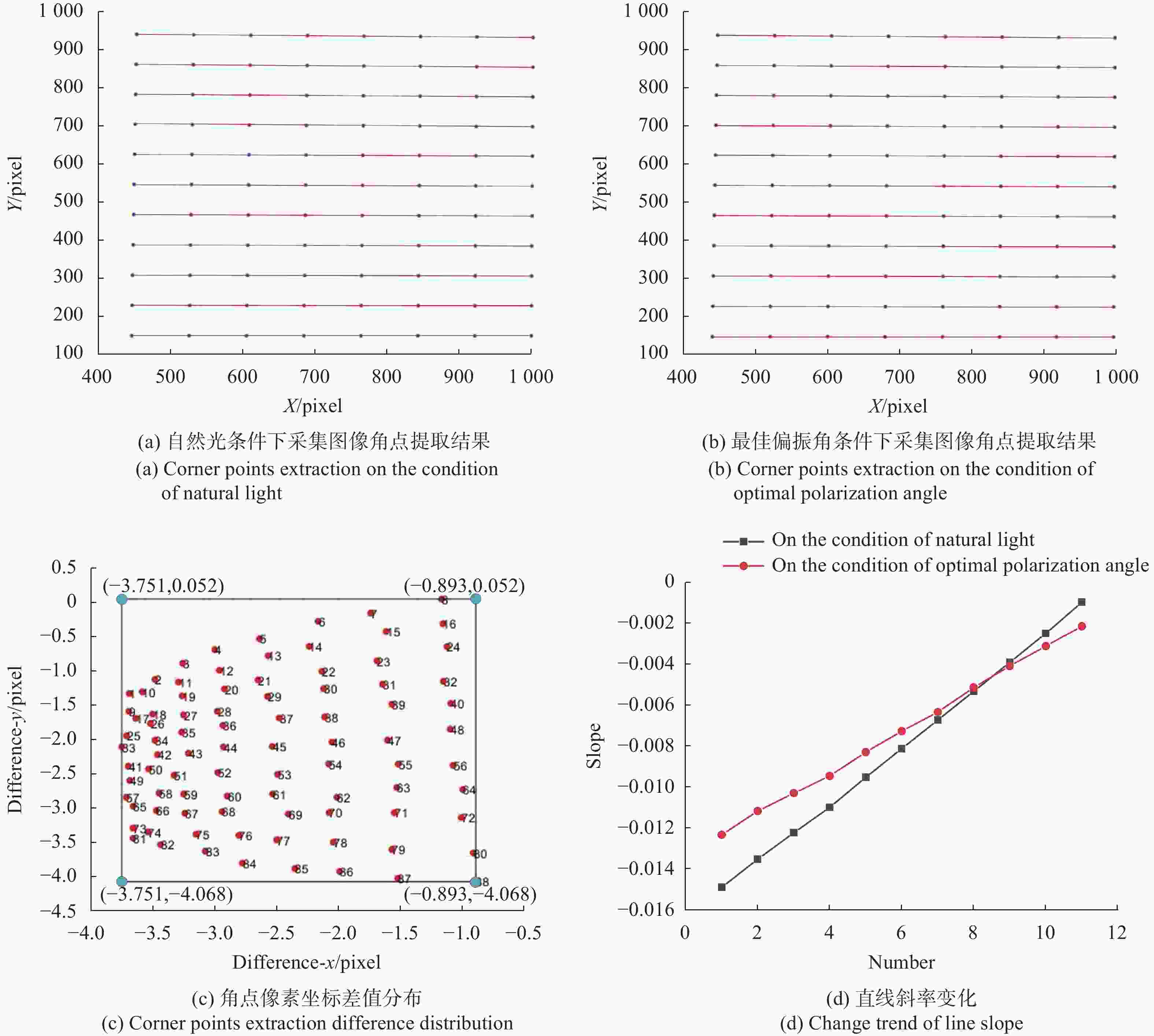
Figure 4. Experimental results of corner points extraction
实验中使用的棋盘靶标由彼此平行的11条水平线组成,当靶标平面近似平行于相机成像面时,由棋盘格图像的角点所拟合的11条水平线也应该是近似平行的,斜率近似相等。如图4(d)所示,黑线表示自然光条件下角点像素坐标拟合的11条水平线斜率的变化趋势,红线表示最佳偏振角条件下角点像素坐标拟合的11条水平线斜率的变化趋势,斜率的标准差分别为0.00984和0.0072。自然光条件下角点像素坐标拟合直线的斜率变化要比最佳偏振角条件下拟合直线的斜率变化更为明显,因此最佳偏振角条件下采集的图像进行角点提取具有更好的精度,证明了文中基于偏振信息采集图像提取角点的可行性和优越性。
-
将摄像机固定到支架上,偏振片固定于镜头前,针对任意一个测量位置,在0°,45°和90°三个不同偏振角度条件下采集靶标图像,根据公式(7)完成最佳偏振角求解,调整偏振片角度至最佳偏振角,采集图像,提取定位特征点(角点),计算靶标位姿。位姿测量精度验证实验包括旋转角度测量实验和位移测量实验。
-
将靶标0°位置记为初始位置。设定靶标顺时针旋转为正,以5°为间隔进行旋转,直至+60°;设定靶标逆时针旋转为负,以5°为间隔进行旋转,直至−60°。靶标各旋转位置在最佳偏振角条件下采集图像,得到的靶标图像以及每个旋转位置对应的最佳偏振角度如图5所示,po表示靶标的旋转位置,op表示计算得出的偏振片在当前旋转位置对应的最佳偏振角。
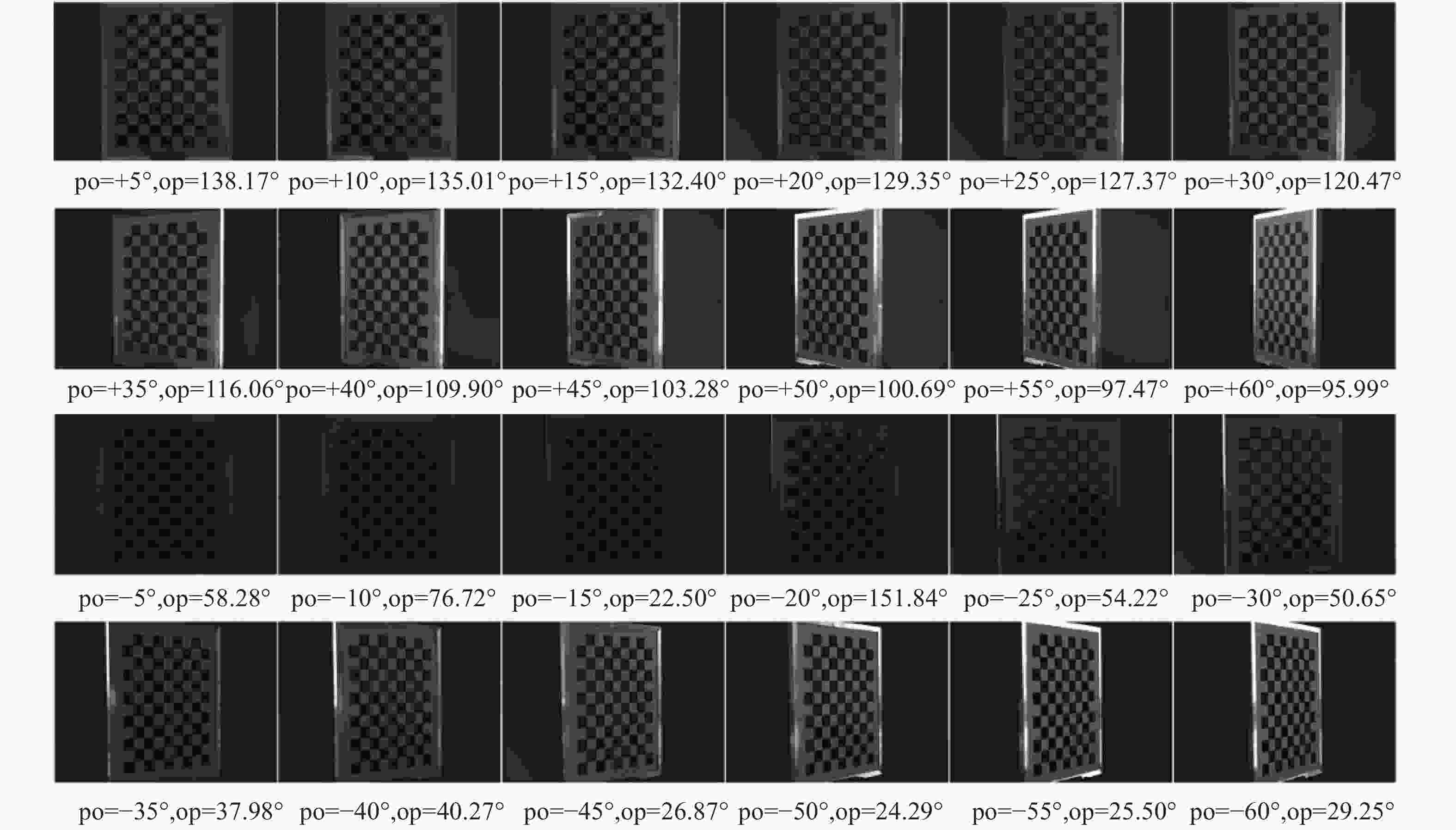
Figure 5. Images collected at each position on the condition of optimal polarization angle
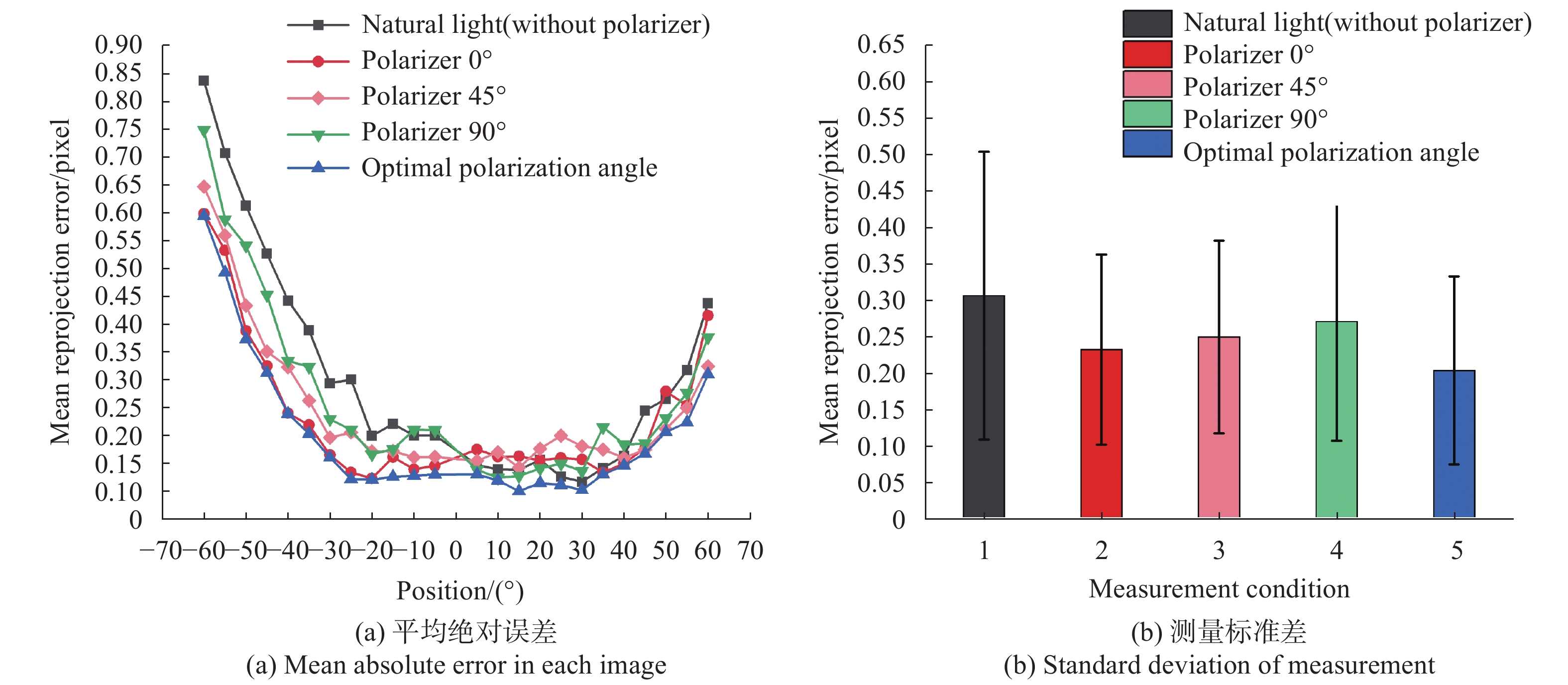
在自然光(不加偏振片),偏振角0°,45°,90°以及最佳偏振角条件下,采集靶标图像,使用文中提出的线性算法计算各位置靶标位姿并计算定位特征点平均重投影误差,实验结果如图6所示,在自然光(不加偏振片)条件下计算得出的定位特征点平均重投影误差更高,在最佳偏振角条件下采集图像,能够有效降低高亮度区域对图像处理的影响,从而提升位姿测量精度,降低靶标位姿测量的平均重投影误差,充分证明了文中方法的优势。
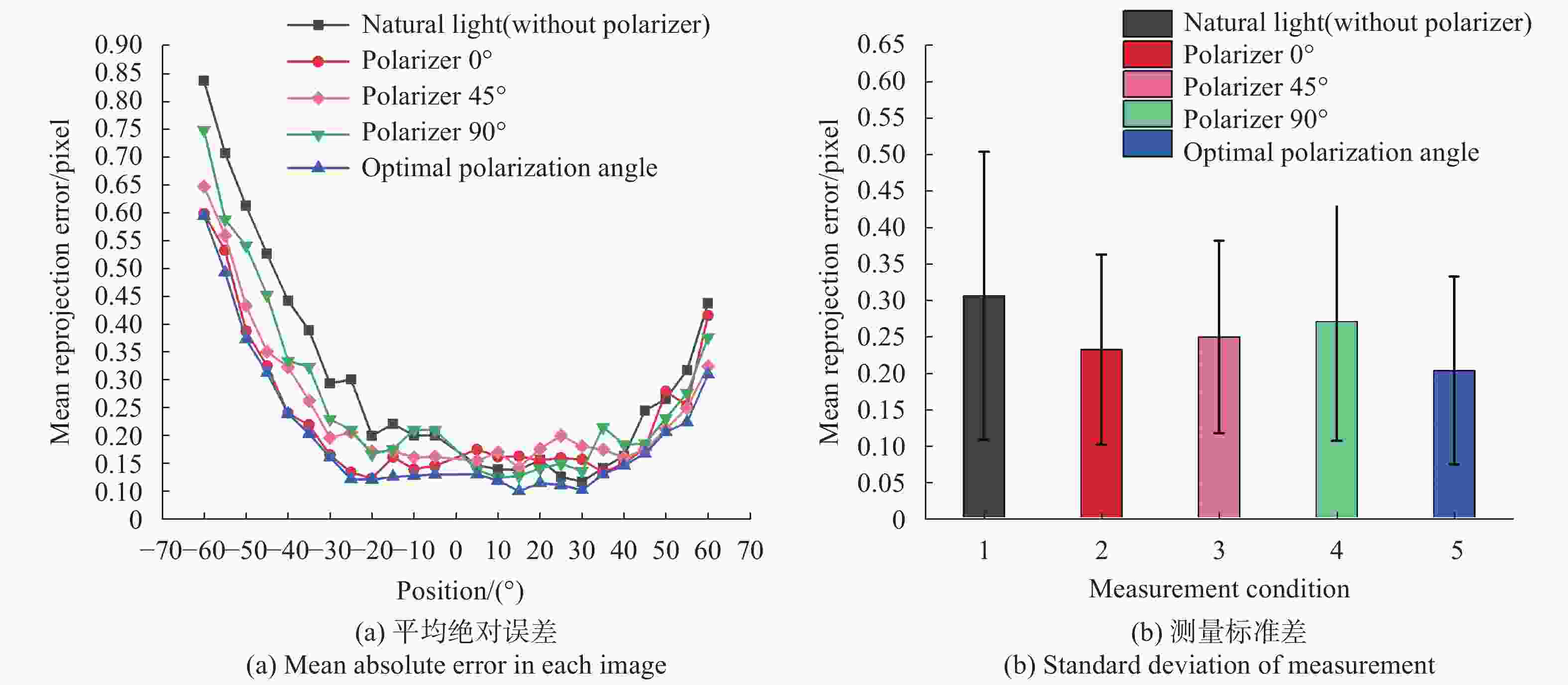
Figure 6. Mean reprojection errors of rotation measurement experiments
在自然光(不加偏振片)与最佳偏振角条件下,使用文中提出的线性算法计算各旋转位置的靶标位姿,得到所有定位特征点x方向与y方向的重投影误差,误差分布图如图7所示。图7(a)为自然光条件下对应的误差分布图,图7(b)为最佳偏振角条件下对应的误差分布图。自然光条件下所有定位特征点在x方向的重投影误差均值为−0.145 pixel,y方向的重投影误差均值为0.125 pixel。最佳偏振角条件下所有定位特征点在x方向的重投影误差均值为−0.05781 pixel,y方向的重投影误差均值为0.0675 pixel,x方向和y方向分别降低了0.09 pixel和0.06 pixel。
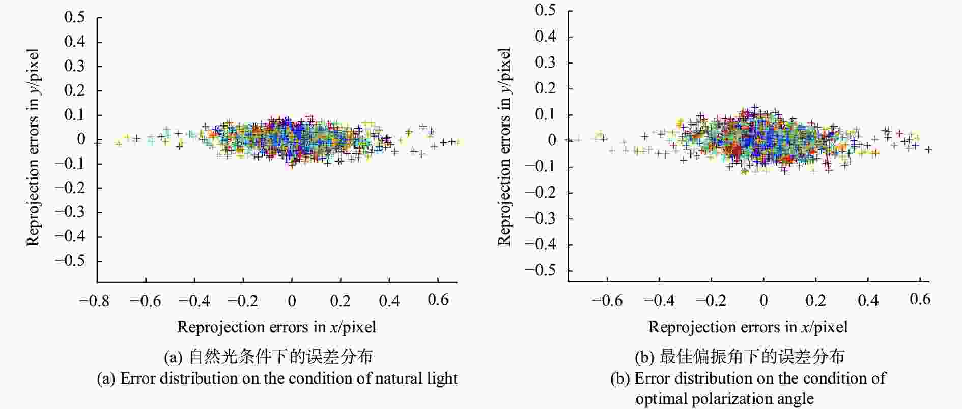
Figure 7. Error distribution of natural light and optimal polarization angle
当靶标旋转角度较大(+40°~+60°和−40°~−60°)时,高亮度区域更为明显,对定位特征点图像坐标提取影响增大,最佳偏振角的效果更为明显,x方向的平均重投影误差降低范围为[0.0203, 0.2184] pixel,y方向的平均重投影误差降低范围为[0.0349, 0.1731] pixel。
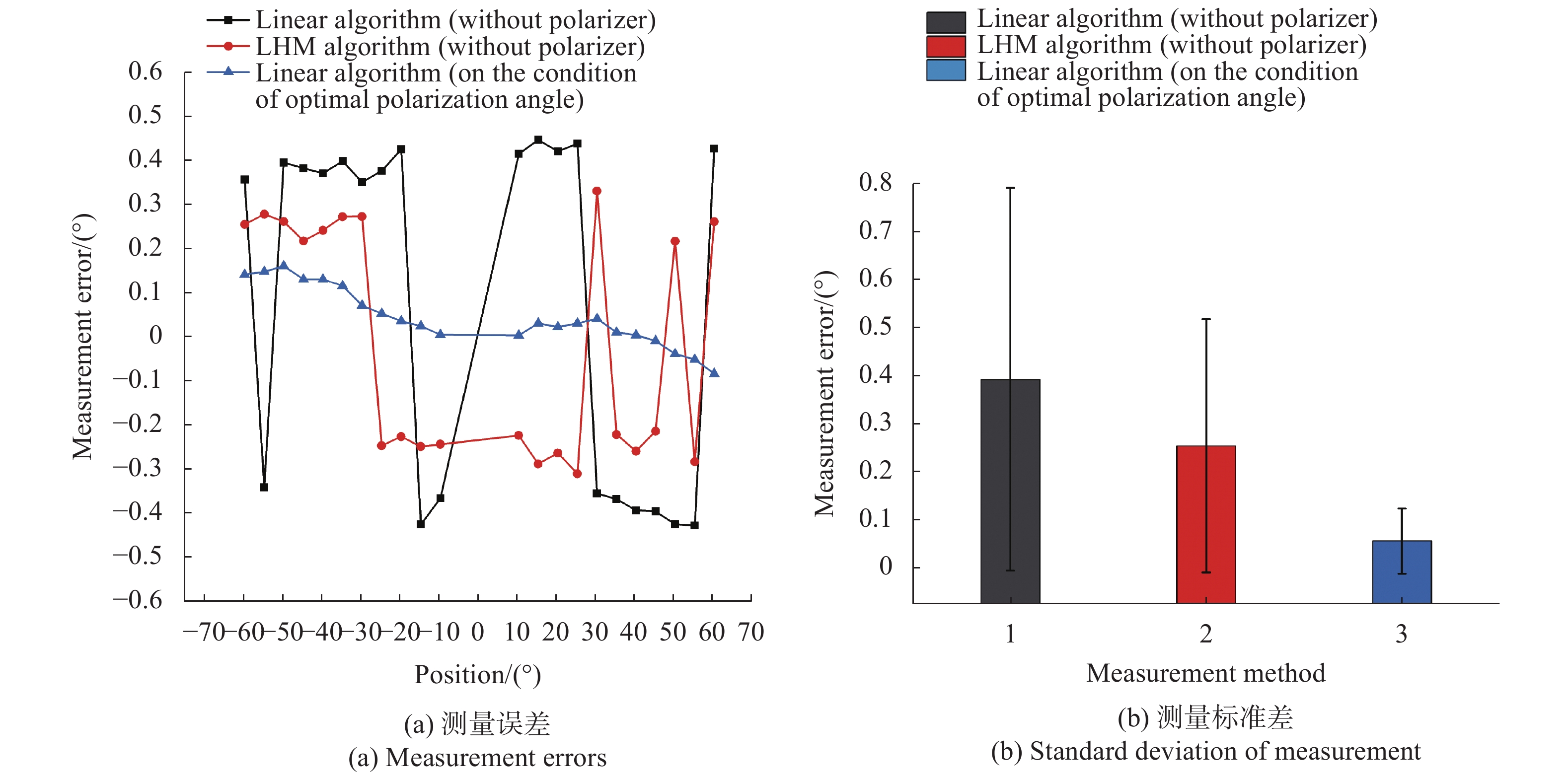
在线性算法(不加偏振片),LHM算法(不加偏振片),线性算法(最佳偏振角)三种条件下分别计算靶标位姿,并计算靶标当前位置相对初始位置(0°)的夹角,测量结果如图8所示,正交迭代算法(LHM)是非线性算法的代表性方法,在自然光(不加偏振片)条件下,其精度优于线性算法。但是在最佳偏振角条件下采集图像,能够有效降低高亮度区域对图像处理的影响,使参与运算的有效定位特征点数量增加,线性算法的精度得到提升,精度优于非线性算法(LHM),测量误差小于±0.16°,测量标准差为0.068°。
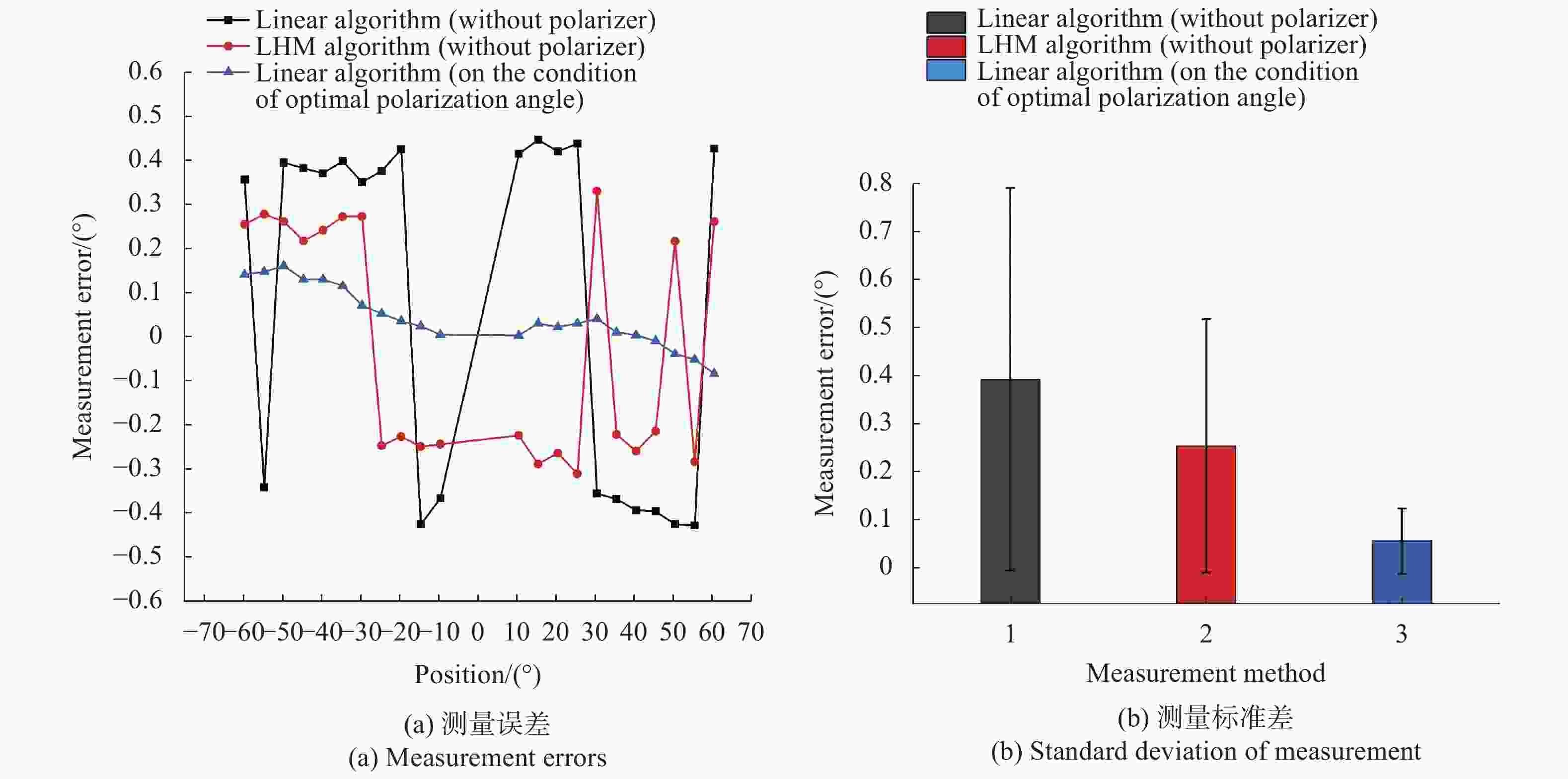
Figure 8. Experimental results of angle measurement
-
将靶标固定在平移台基准位置(0 mm)处,靶标每次平移距离为0.5 mm,从0 mm移动到20 mm处共41个位置。在自然光(不加偏振片)和最佳偏振角条件下,使用文中提出的线性算法计算各位置靶标位姿并计算定位特征点平均重投影误差,实验结果如图9所示,在最佳偏振角条件下采集图像,能够有效降低高亮度区域对图像处理的影响,从而提升位姿测量精度,降低靶标位姿测量的平均重投影误差。

Figure 9. Mean reprojection errors of translation measurement experiments
在线性算法(不加偏振片),LHM算法(不加偏振片),线性算法(最佳偏振角)三种条件下分别计算靶标位姿,并计算靶标当前位置相对初始位置(0 mm)的距离,测量结果如图10所示。LHM算法在自然光(不加偏振片)条件下,其精度优于线性算法。但是在最佳偏振角条件下采集图像,能够有效降低高亮度区域对图像处理的影响,使参与运算的有效定位特征点数量增加,线性算法的精度得到提升,精度优于非线性算法(LHM),测量误差小于±0.05 mm,测量标准差为0.034 mm。
综上,在旋转角度测量实验中,最佳偏振角条件下的测量相比于自然光条件下的测量,平均重投影误差降低了0.101 pixel。在最佳偏振角条件下使用线性算法测量靶标位姿,角度测量误差小于±0.16°,测量标准差为0.068°。在位移测量实验中,在最佳偏振角条件下的测量相比于自然光条件下的测量,平均重投影误差降低了0.046 pixel。在最佳偏振角条件下使用线性算法测量靶标位姿,位移测量误差小于±0.05 mm,测量标准差为0.034 mm。

Figure 10. Experiment results of displacement measurement errors
-
文中在相机镜头前加装线偏振片,提出基于最佳偏振角的线性位姿测量方法。根据Stokes矢量建立最佳偏振角度求解模型,在使用最佳偏振角度的前提下采集定位特征点图像,提取定位特征点图像坐标;建立线性位姿求解模型,求解被测物体位姿。进行了角点提取实验和测量精度验证实验,实验结果表明,在最佳偏振角条件下采集被测物体图像,能够减少高亮度区域,精确提取定位特征点图像坐标,使参与位姿求解的有效定位特征点数量增加,提高了线性位姿测量方法的精度。在−60°~+60°的测量范围内,角度测量误差小于±0.16°,测量标准差为0.068°。在0~20 mm的测量范围内,位移测量误差小于±0.05 mm,测量标准差为0.034 mm。文中提出的测量方法为位姿测量提供了一种新的可行的手段。该方法可应用于工业机器人对准技术,机器人手眼标定,组合位姿测量等领域。
Research on linear pose measurement method based on optimal polarization angle
doi: 10.3788/IRLA20210241
- Received Date: 2021-04-13
- Rev Recd Date: 2021-08-23
- Publish Date: 2022-04-07
Fund Project:
National Natural Science Foundation of China (youth project)(51605332,51905378);Tianjin Natural Science Foundation(youth project)(19JCQNJC04200,20JCQNJC00360);Tianjin Technological Innovation Guidance Special Fund Enterprise Science and Technology Commissioner Project(20YDTPJC00450)
-
Key words:
- pose measurement /
- optimal polarization angle /
- linear algorithm /
- Stokes vector
Abstract: As to pose measurement technology based on visual image, the global convergence of the nonlinear algorithm is uncertain, and the results depend on the selection of initial values, so the robustness of pose measurement cannot be guaranteed. Linear pose measurement algorithms have relatively high requirements for image processing. If the image coordinates of feature points are not accurately extracted, the pose measurement accuracy will be reduced. On the condition of natural light, the camera collects the image of positioning feature points, and the existence of high light regions in the image have some impacts on the extraction accuracy of feature points, which reduces the number of effective feature points and affects the pose measurement accuracy. To solve the problems above, a linear pose measurement method based on the optimal polarization angle was proposed. The camera was equipped with a polarizer. The optimal polarization angle solution model was established according to the Stokes vector. On the premise of the optimal polarization angle, the feature points images were collected and the image coordinates of the feature points were extracted. The linear solving model was established to solve the object pose. The experimental results show that this method can effectively reduce the high light regions in the image, which improve the imaging quality and improve the linear pose measurement accuracy. In the measurement range of −60° to +60°, the angle measurement error is less than ±0.16°. In the measurement range of 0 to 20 mm, the displacement measurement error is less than ±0.05 mm.


 DownLoad: