


-
3D打印技术是一种快速成型技术,与减材制造相反,它是一种以数字模型文件为基础,运用粉末状金属或非金属可粘合材料,通过逐层打印的方式来构建物体的技术[1],已经在工业设计、建筑、工程等领域得到应用,在突破传统工艺限制的同时也极大地提高了生产效率。碳化硅材料具有较高的弹性模量,适中的密度,较小的热膨胀系数,因此具有比刚度较高及稳定性较好等优秀的物理性质[2],已应用于航空航天等领域。
主承力结构是光学遥感相机的关键部件,直接决定了相机的稳定性,影响相机性能和成像质量。在受到严格空间包络及质量约束的情况下,稳定性是主承力结构的设计重点[3]。
因此,一方面为了提高主承力结构的轻量化程度,从而达到降低对卫星资源需求、节约发射成本的目的;另一方面,碳化硅结构具有良好的力、热稳定性,可为实现在轨无调焦设计奠定基础。文中将3D打印技术和碳化硅材料相结合,研制出碳化硅3D打印的主承力结构,拓展了打印技术的应用范围。目前,国内外对于3D打印技术研制反射镜等非承力结构较多,应用于主承力结构的研制极少,参考资料和相关经验匮乏,这也给研制碳化硅主承力结构增加了难度。
-
相对于传统的制造工艺,3D打印技术可在不损失结构性能和生产效率的前提下,制造出相对复杂的结构,可以提供给工程师宽阔的设计空间,设计出更加复杂的结构形式,极大释放了设计的自由度。美国GE公司先进的ATP发动机中,30%以上的部件使用3D打印技术,优化了零件结构,提高材料使用率。俄罗斯科学家研制的Tomsk-TPU-120卫星的外壳和电池组均由3D打印而成,实现了一体化设计。
材料是3D打印技术的关键,其性能、工艺等直接决定了最终产品的性能。文中的碳化硅材料具有比刚度高、热稳定好等优势,但其硬度高、加工性差的特点也制约应用范围。3D打印技术正好可以解决这一弊端,发挥其良好的材料性能。
遥感相机主承力结构的功能是支撑光学反射镜及焦面组件,并保证光学系统所要求的各光学元件与像面之间的准确位置关系[4],它不仅要确保光学性能良好、稳定,而且还要满足空间环境适应性和复杂光学系统装调要求及中间环节结构精度要求。针对上述要求,碳化硅3D打印技术可以提供解决方法。但值得注意的是,由于碳化硅的断裂韧性较低,易于出现机械损伤,脆性大。因此,针对碳化硅产品,在使用过程中防止发生断裂也是设计的重点之一[5],是进行结构分析的重要方面。
-
主承力结构除了精确支撑各光学元件及成像器件外,还要安装配其他能组件[6]。文中所涉及的主承力结构不仅要考虑传统结构设计的一般性原则[7],还要考虑碳化硅3D打印技术特殊性,设计方法及具体流程如下:(1)根据光学系统对主承力结构进行构型,可为各光学元件及卫星提供机械接口,且外形尺寸在最大外包络尺寸内;(2)进行优化设计,在满足质量限制的前提下,要求具有足够的刚度和强度,以适应力学环境;(3)针对3D打印工艺和碳化硅材料特点进行强度校核,并确保打印尺寸精度。如不满足要求,则需针对不满足项进行结构优化设计;(4)增加负载后,主承力结构仍具有良好的结构稳定性,可以克服外界振源对光学系统的影响;(5)在一定温升下,要求热稳定性较高,满足光学系统对反射镜位置度的要求。
-
离轴三反相机具有长焦距、大孔径、无中心遮拦等优势[8],文中所论述的遥感相机采用离轴三反的全反射式光学系统,如图1所示,光线依次经过主、次、三镜后,再由折镜将光线分成两个焦面通道,两个焦面通道成90°角。

Figure 1. Off-axis three-mirror reflective optical system
综合卫星对外包络尺寸和质量的要求,以及反射镜和焦面组件的尺寸、质量,主承力结构要求外包络在420 mm×400 mm×450 mm以内、质量小于4.5 kg。依据设计经验,采用传统钛合金铸造,质量至少为7.2 kg,无法满足要求,需要采用碳化硅3D打印技术研制该主承力结构。
主承力结构有两种形式:箱式结构和桁架式结构。箱式整体结构紧凑,具有良好的力学性能,无装配应力,适用于离轴相机,故采用箱式结构作为构型方案。在构型设计时,尽量采取对称结构并合理布局,降低转动惯量和重心,以增加稳定性。在主承力结构的前端安装焦面组件和次镜组件,后端安装主、三镜组件,底部设置与卫星的接口,初步构型如图2所示,外包络为400 mm×370 mm×430 mm。
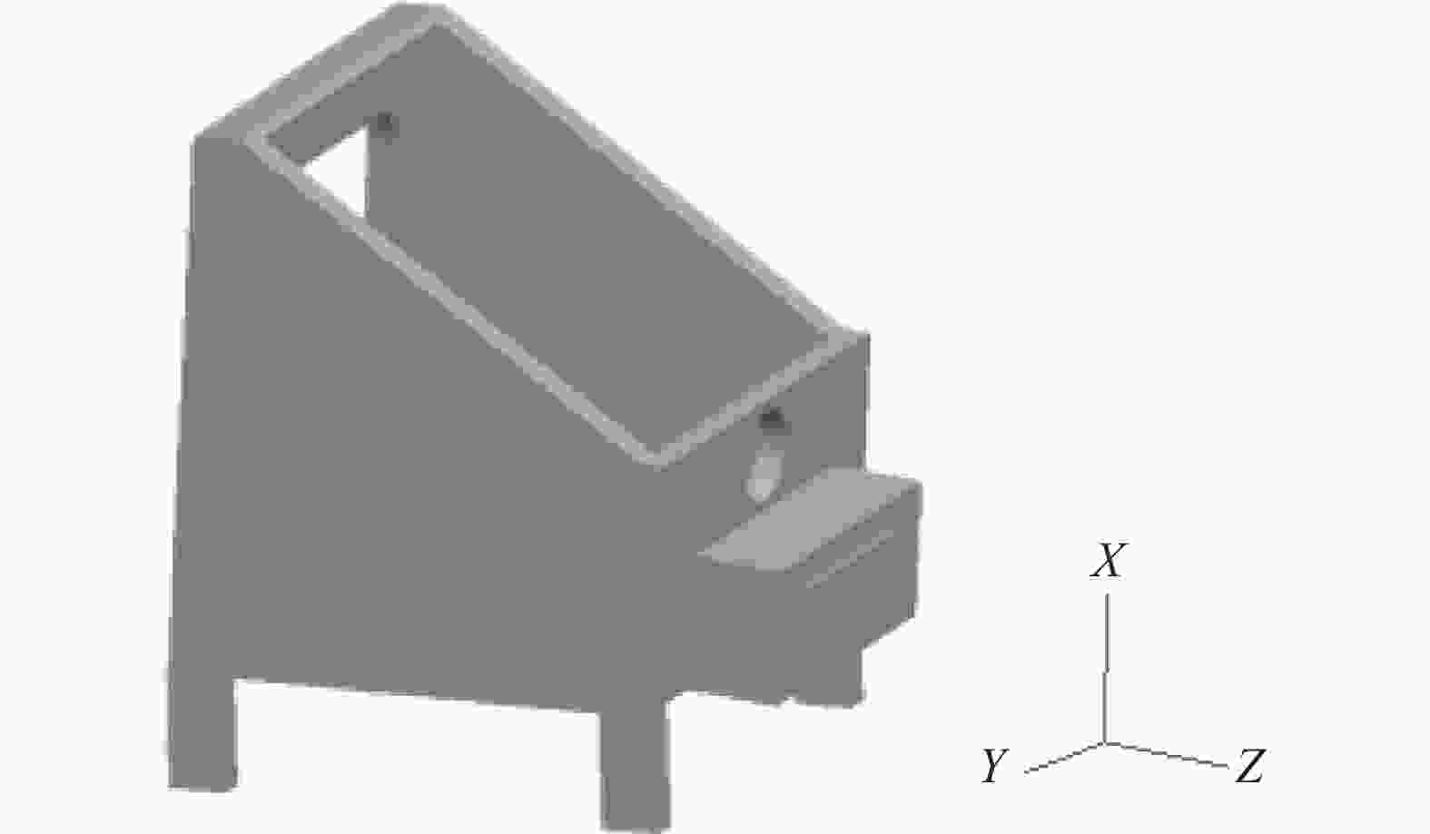
Figure 2. Initial configuration of main bearing structure
-
拓扑优化是一个从结构到强度,再从强度到结构的多次反复、不断逼近的过程。由于受到包络尺寸和质量的限制,要求在体积约束下求最小柔度,即最大刚度。以单元相对密度为变量,结构最小柔度为目标函数,基于变密度理论SIMP法的周期性拓扑优化问题的数学模型表达式为[9]:
式中:C为柔度值;U为各单元的位移向量;F为作用在单元上的载荷向量;K 为刚度矩阵;Vmax和VX表示允许的最大体积和优化后结构体积;Xmin为拓扑变量下限,取拓扑变量下限值Xmin=10-3。
上述模型需根据3D打印的特殊性补充以下三点:(1)结构优化时主要针对内部进行;(2)优化目标为体积最小,可节省材料和打印时间;(3)优化时需要考虑其稳定性约束,在文中即约束最小厚度t,寻求主框架的体积最小化目标:
3D打印一般使用各向同性材料,可以采用Von Mises应力作为各单元的应力度量[10]:
式中:
$ {\sigma }_{1} $ 、$ {\sigma }_{2} $ 和$ {\sigma }_{3} $ 为三个方向的主应力。为求体积极小值,使用渐进优化法中的体积进化率系数。无负载的情况下,在体积逐渐减小的过程中,各单元的应力逐渐增大,选取应力最小的构型为最终结构形式。综合公式(1)~(3),使用拓扑优化技术对主承力结构侧壁进行轻量化设计,同时在安装脚处进行加强。在结构突变处,使用大尺寸圆角进行圆滑过渡,降低应力集中。由于碳化硅3D打印技术不受传统工艺以及生产效率的限制,可实现一体化设计,减少零件装配和局部轻量化。多次迭代后收敛,最终优化结果如表1所示,可以为反射镜组件和焦面组件提供稳定的安装平面。Min thickness/mm Volume/m3 Appearance/mm Weight/kg 5 1.53E-3 400×370×430 4.2 Table 1. Results of optimization of main bearing structure
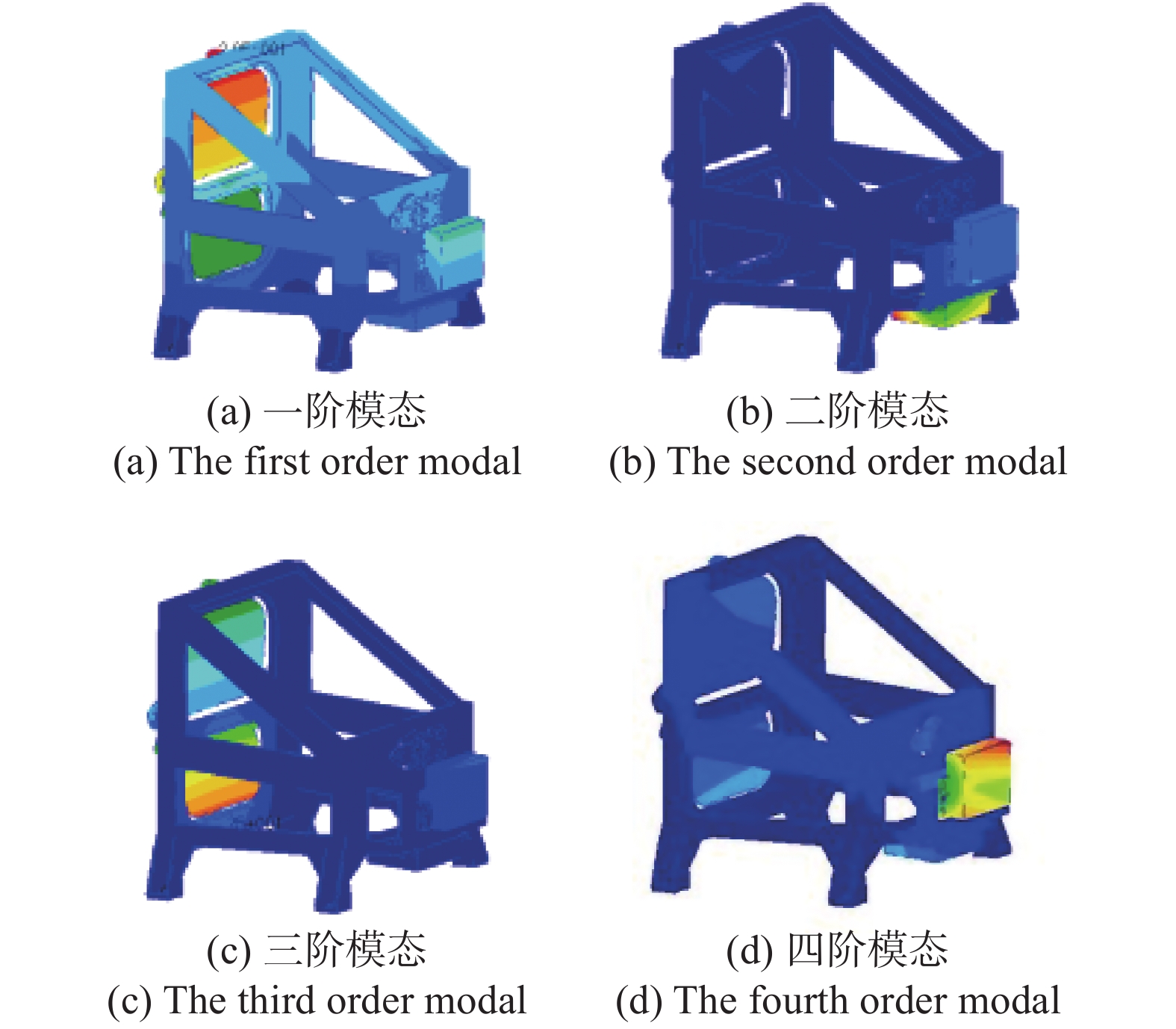
对主承力结构进行仿真分析,前四阶频率分别为639.9 Hz、655.7 Hz、707.1 Hz和819.9 Hz,振型如图3所示,总重减少至4.2 kg,较传统制造方案减重约41.6%。前后两端的安装点没有较大摆动,表明优化后主承力结构仍有较高刚度。

Figure 3. The order modals of main bearing structure
-
3D打印是基于离散/堆积原理,通过材料的逐渐累积来实现制造的技术[11],常以粉末作为主要原材料,但粉末材料存在不均匀性,且部分成型粉末比表面积大、表面能较高,易出现团聚现象。在打印堆积过程中会产生因受到重力影响而导致打印精度出现偏差的情况 [12]。
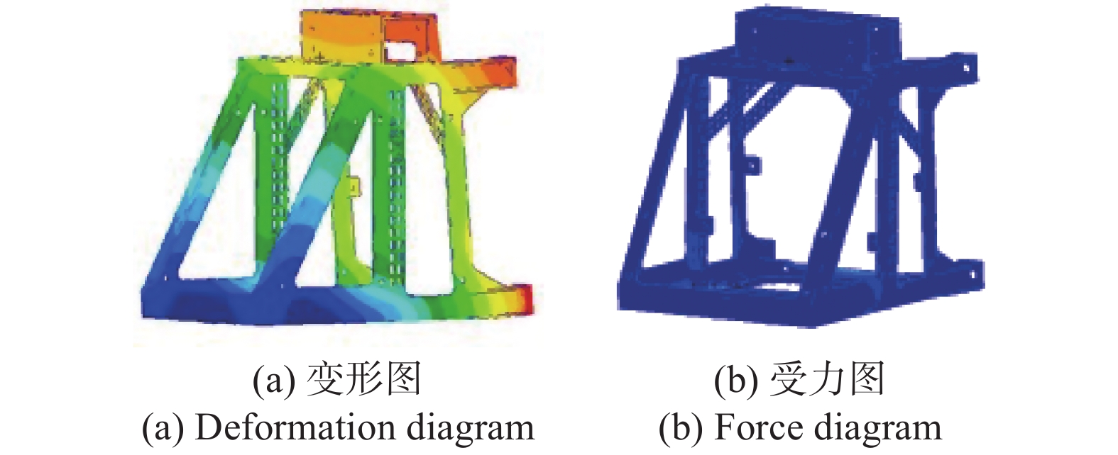
文中的主承力结构沿+Z方向进行堆积。使用的碳化硅粉体在打印时可承受2.6 MPa的抗弯强度。为提高打印稳定性,在主承力结构前端面与侧板之间增加了支撑梁。堆积方向仿真分析结果如图4所示,最大受力为1.8 MPa,满足打印工艺强度要求。最大变形处为0.002 mm,也小于后续补充加工和镜头装调位置余量。

Figure 4. Simulation analysis of satacking direction
-
碳化硅晶体结构具有同质多型体的特点,不同的碳化硅微结构的力学性能不尽相同。针对其力学性能的研究已经取得了一定程度的进展,但仍未形成统一的力学参数标准。与金属材料相比,碳化硅材料脆性较大,强度分散性大,可靠性低。使用直接拉伸法测量块状试样,强度最低的只有10 MPa,最高不超过112 MPa。从可靠性角度出发,将10 MPa作为力学强度校核标准。
进行整机分析时,在各安装点上增加负载,以模拟装配后的产品状态。遥感相机整机前四阶频率分别为231.1 Hz、272.5 Hz、288.6 Hz和314.7 Hz,振型图如图5所示,主承力结构没有较大的摆动,表明稳定性较高。仅以主承力结构为研究对象,X向前四阶频率为288.6 Hz、399.1 Hz、455.9 Hz和730.8 Hz;Y向前四阶频率为272.5 Hz、352.4 Hz、386.7 Hz和435.1 Hz;Z向前四阶频率为231.1 Hz、314.8 Hz、545.2 Hz和581.2 Hz。
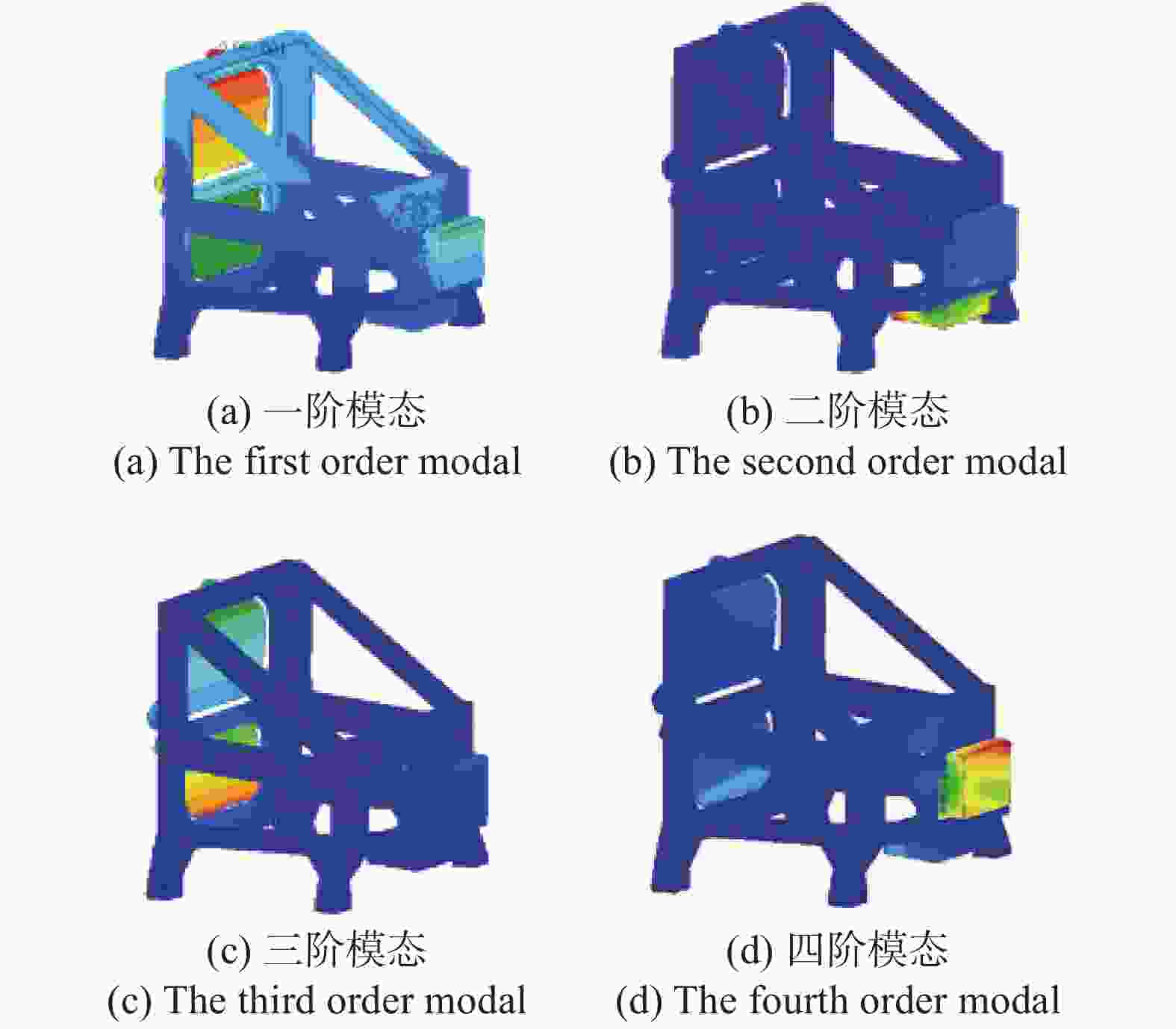
Figure 5. The order modals of remote sensing camera
按鉴定级振动试验,遥感相机加速度响应10 g计算,X向、Y向和Z向最大应力为6.1 MPa、8.1 MPa和9.4 MPa,均小于10 MPa,满足可靠性要求,各方向的变形云图如图6所示。
Figure 6. 10 g overload deformation diagram of camera
低阶频率直接反映动态刚度特性。相机一阶频率大于100 Hz,具有较高的动态刚度,在100 Hz内正弦振动响应无明显放大。随机振动指那些无法用确定性函数来描述、但又有统计规律的振动,具有难以预测的特点,频率范围为10~2 000 Hz。随机激励以功率谱密度(PSD)的形式描述,通过计算PSD响应的统计均方根值(RMS)来衡量随机振动的剧烈程度。卫星平台随机振动均方根值为2.0 grms,输入条件如表2所示。
Frequency range/Hz Power spectral density/g2·Hz−1 10-65 0.000147-0.0155 65-100 0.0155 100-150 0.0077 150-500 0.00617 500-2 000 0.00617-0.000000617 Table 2. Input conditions for random vibration
反射镜和焦面是相机的核心部件,易损坏,为保证经历发射后光学系统依然工作正常,进行随机振动仿真分析时,将主镜、次镜、三镜、分光镜以及两个焦面组件安装点作为测点进行分析。以主镜组件安装点为例,仿真分析时,功率谱密度曲线如图7所示,与另外两个方向相比,Y向的功率谱密较大,表明Y向的随机振动响应较大。

Figure 7. Curves of power spectrum density
从分析结果看,主镜组件安装点、次镜组件安装点、三镜组件安装点和分光镜组件安装点最大响应分别为8.14grms(Y向)、4.07grms(Z向)、5.04grms(Y向)和4.03grms(Z向),焦面组件安装点最大响应分别为4.01grms(Z向)和3.27grms (Z向),各侧点处的响应均有不同程度的放大,除Y向主镜组件、三镜组件安装点外,其他安装点的响应均在2.2倍以内。这是由于主镜、三镜组件质量较大,与其他方向相比,Y向受到外包络的限制,跨距较小、弯矩较大造成的,可考虑增加隔振器来降低随机振动响应,保证其稳定工作。
-
主镜和次镜在相机的两端,较小的轴间距或俯仰偏离会对成像质量产生较大的影响,因此要对各反射镜组件安装点进行热稳定性分析。
反射镜均采用碳化硅材料,线膨胀系数与主承力结构一致,有利于消除热应力,对均匀温度变化不敏感。在10 ℃温升环境下,主镜组件安装点(PMAMS)、次镜组件安装点(CMAMS)和三镜组件安装点(TMAMS)变形如表3所示。可以看出,反射镜安装点的变形量较小,表明主承力结构热稳定性较高,也为遥感相机实现在轨无调焦设计奠定了一定基础。
Deformation PMAMS CMAMS TMAMS X displacement/mm 0.0116 0.0064 0.0069 Y displacement/mm 0.0004 −0.0009 0.0004 Z displacement/mm −0.0055 0.0063 −0.0042 X turning angle/(″) 0.099 0.779 −0.142 Y turning angle/(″) − 0.054 0.136 0.361 Z turning angle/(″) 0.017 −0.588 −0.092 Table 3. Deformation of mirror mounting points
-
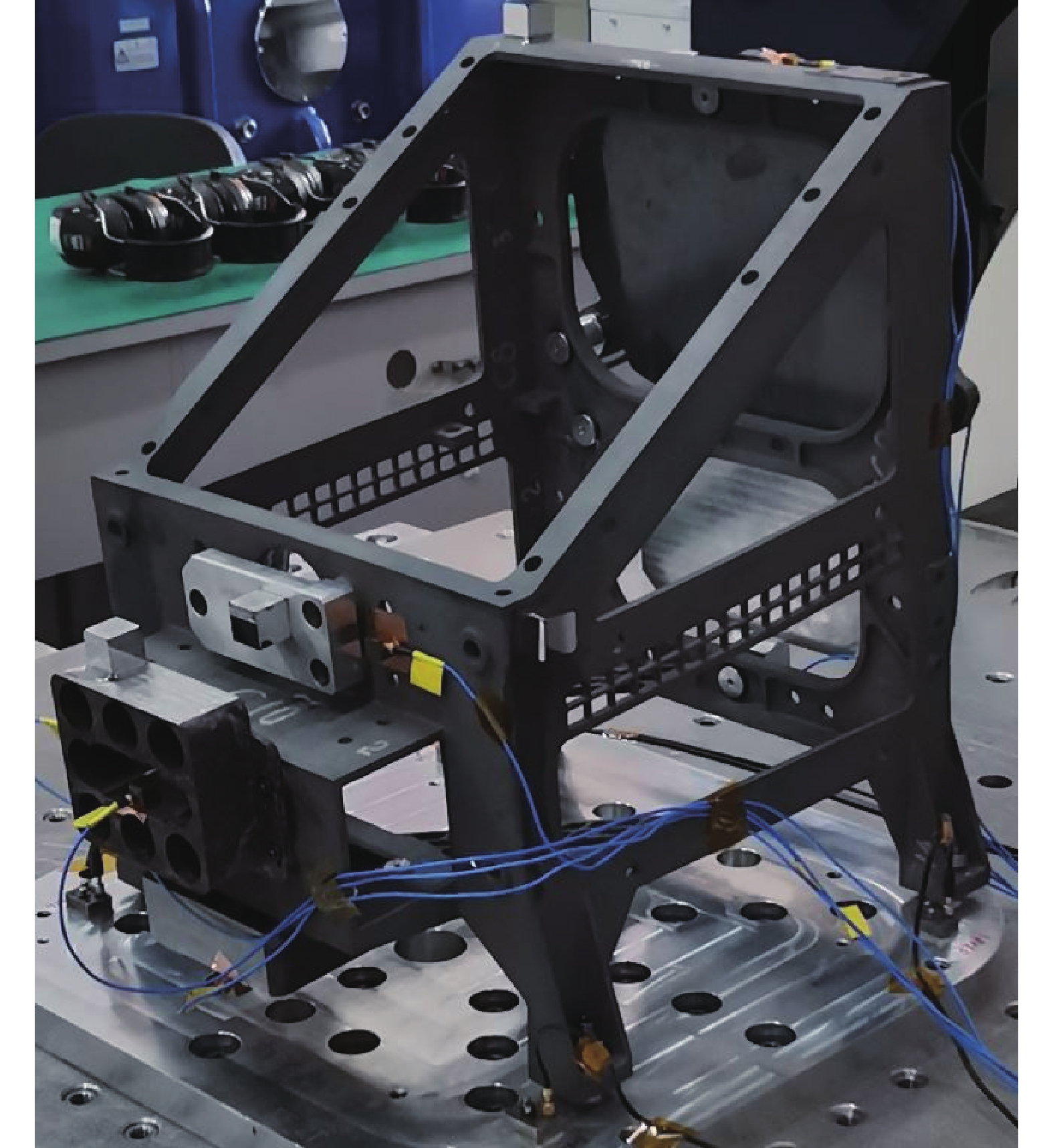
针对该相机进行力学环境试验测试,主承力结构在X向、Y向和Z向的基频分别为287 Hz,265 Hz和224 Hz,满足使用要求,与仿真结果一致性超过95%,试验现场如图8所示。
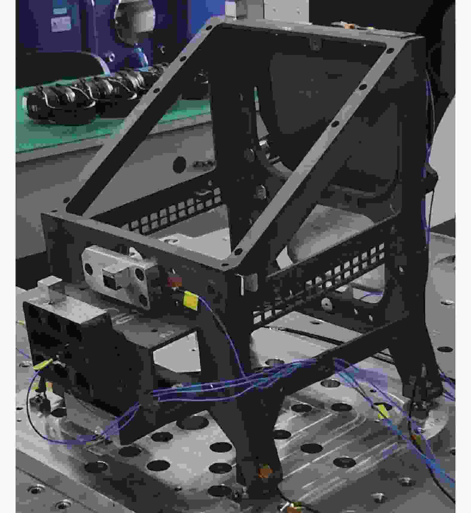
Figure 8. Mechanic vibration test
除主镜、次镜、三镜组件安装点外,将折镜组件安装点(FMAMS)、焦面1安装点(FP1AMS)和焦面2安装点(FP2AMS)选为试验测点,当按表2的条件进行试验时,力学测试结果如表4所示。
Key points RMS acceleration/grms Magnification PMAMS X-direction:2.68 1.34 Y direction:7.96 3.98 Z-direction:3.96 1.98 CMAMS X-direction:2.26 1.13 Y-direction:3.11 1.56 Z-direction:3.71 1.86 TMAMS X-direction:2.46 1.23 Y-direction:4.96 2.48 Z-direction:3.96 1.98 FMAMS X-direction:2.42 1.21 Y-direction:3.32 1.66 Z-direction:3.78 1.89 FP1AMS X-direction:3.34 1.67 Y-direction:3.11 1.56 Z-direction:3.67 1.84 FP2AMS X-direction:2.98 1.49 Y-direction:3.02 1.51 Z-direction:3.08 1.54 Table 4. Mechanical test results of key points
从测试结果可以看出,试验结果与仿真分析结果基本相同,一致性超过90%。除因试验设备引入的测量误差外,两者之间的差异主要是由碳化硅粉末力学性能不均匀导致的。
通过试验进一步验证了所论述的主承力结构设计方法的合理性和正确性,证明了采用碳化硅3D打印技术研制的主承力结构具有较高的稳定性,能够承受发射段恶劣环境的考核,对复杂环境具有良好的适应能力。
-
文中首先介绍了碳化硅材料和3D打印技术的特点以及能够给予遥感相机主承力结构带来的设计突破。针对二者的特点,总结了采用碳化硅3D打印技术研制主承力结构的设计方法。随后,以一款三反离轴遥感相机主承力结构为例进行结构设计,验证了该方法的可行性和正确性,为碳化硅3D打印技术在空间光学遥感相机研制应用方面提供了一定的思路和借鉴。
采用碳化硅3D打印技术研制的主承力结构外包络为400 mm×370 mm×430 mm,一阶频率为639.9 Hz,质量仅为4.2 kg,与传统方案相比减重约41.6%,具有良好的力、热稳定性,为遥感相机在轨实现无调焦设计奠定了基础。另一方面,轻量化程度的提高降低了对卫星资源的需求,节约了发射成本,提高了产品竞争力。
Design and verification of main bearing structure of remote sensing camera based on SiC 3D printing
doi: 10.3788/IRLA20210267
- Received Date: 2021-04-24
- Rev Recd Date: 2021-06-30
- Publish Date: 2022-04-07
-
Key words:
- silicon carbide /
- 3D printing /
- remote sensing camera /
- main bearing structure
Abstract: The rapid prototyping technology of 3D printing is becoming more and more mature, and its application scope is more and more extensive. Silicon carbide material has excellent physical properties such as high elastic modulus, specific stiffness and good stability. In order to make the main bearing structure of remote sensing camera break through the limitations of traditional technology and design ideas, improve the light weight and obtain better mechanical and thermal stability, the silicon carbide as raw material was used and 3D printing manufacturing method was adopted to develop the main bearing structure. Firstly, the advantages and characteristics of silicon carbide 3D printing technology were introduced. Then, according to the technical characteristics, the design method of the main bearing structure was combed. Then, according to the design method, structural design, simulation and optimization were carried out. Finally, the outer envelope of the main bearing structure was 400 mm×370 mm×430 mm, the first-order frequency was 639.9 Hz, and the weight was only 4.2 kg, which was 41.6% lower than the traditional scheme. It has good mechanical and thermal stability and meets the use requirements. After mechanical test, it meets the design expectation.


 DownLoad: