


-
嵌入式光纤光栅滑觉传感器现多用于智能仿生皮肤的研究[1]。目前国内外对滑觉传感器的研究不断朝着小型化和智能化的方向发展[2]。检测该功能的传感器大多数为电容传感器和光波导传感器[3-7],以上传感器存在着抗电磁干扰能力较弱、柔性不足等问题。而光纤布拉格光栅(Fiber Bragg Grating,FBG)体积小,灵敏度高,响应速度快,近年来被广泛应用于桥梁隧道、航天航空等各个领域[8-11]。2018年,钱穆云等人将二维分布式 FBG传感阵列埋置于封装体中,实现了触觉、滑觉信息的测量[12]。2018年,Nobutomo M等人研究了采用滑差方式监测机械手的抓握控制能力[13]。2019年,Feng等人设计了一种基于光纤光栅机械手指尖滑移传感器,实现了滑移和表面粗糙度的检测[14]。2019年,王彦等制作了基于光纤光栅的柔性传感器,采用控制变量法单一性地测试了对温度、力觉等信息的感知和响应[15]。2020年,孙世政等人提出了一种基于光纤布拉格光栅的双层分布式传感单元,将触觉与滑觉信号分离[16]。许会超等人采用3×3 FBG传感阵列作为柔性传感元件聚二甲基硅氧烷材料作为双层柔性基体,制作了柔性触觉传感器 [17]。
上述所提到的研究中大多只是对触觉信息的测量或将触觉与滑觉交叉响应分离的问题,没有对物体整个运动状态进行监测。因此文中提出了一种在硅胶中嵌入FBG阵列的柔性滑觉传感器,并增加了与应变传感器相同封装形式的温度补偿光栅,实现了对物体运动状态的实时监测。该传感器模型通过将物体运动所产生的应力转换为FBG中心波长响应输出,再对输出响应进行解算从而获取物体实时运动状态信息。
-
该系统主要由扫频激光器、耦合器、光隔离器、解调模块、温度补偿模块等组成,如图1(a)所示。

Figure 1. (a) Overall structure of the system; (b) Direction and speed of the object's movement
该测试系统是针对监测物体滑动路线的研究,物体按一定路线在硅胶块上滑动时,物体施加在硅胶块上的应变导致光纤光栅传感器阵列中心波长发生偏移,解调器上位机实时显示中心波长的偏移以及物体运动时间,文中建立光纤光栅中心波长偏移量与物体位置之间关系,从而实现对物体滑动路线的监测。
-
FBG的传感原理是通过光纤芯进行反射和透射,在外界环境感知应变时,反射和折射的光会发生变化,从而达到测量目的。
根据耦合理论有:
式中:
${\lambda _B} $ 为反射波波长;${n_e} $ 为光纤光栅的有效折射率;$\varLambda $ 为光栅周期。当光纤光栅周围应力和温度变化会引起折射率和栅距的变化,导致FBG波长${\lambda _B} $ 的移位,满足线性关系式:式中:
$ \Delta {\lambda _B} $ 为FBG波长变化量;$\alpha $ 为光纤光栅的热膨胀系数;$\xi $ 为光纤光栅热光系数;$\Delta {T}$ 为温度变化;${{{P}_e}}$ 为光纤光栅弹光系数;$\varepsilon $ 为光纤光栅轴向应变。当环境温度发生变化时,系统中的温度补偿FBG产生一定的温漂补偿应力传感器温漂,因此在后续测量过程中只考虑应变所引起的中心波长的偏移。
首先对光纤光栅进行标定实验,得到每一个光纤在每一个小区域处的分辨率K。36个不同的小区域分别对应8个不同FBG的分辨率。当物体在不同位置时,FBG中心波长偏移量有不同的响应。
根据每一个FBG的响应正负以及响应程度,可以初步判定物体所在区域,假设物体所在图1(b)所示区域,该区域内有1~9个小区域,进一步确定物体所在位置则需要知道每一小区域处两个FBG的分辨率比值,任意区域皆满足关系式:
式中:
$\Delta {\lambda } $ 为光纤光栅传感器中心波长偏移量(其中m=1,2,···,8;n=1,2,···,8);$ {K_m} $ 表示第m个光纤光栅传感器在点$\left( {{x_i},{y_j}} \right) $ 处的系数。由于光纤光栅位移监测模块中所铺设的光纤是完全对称的状态,以横轴0~75 mm、纵轴75~150 mm的范围为例,该范围分为9个小区域,按照由左到右、由上到下的顺序分别命名为A1、A2、A3、A4、A5、A6、A7、A8、A9,设Δλ2/Δλ1=Δλ21=b21, Δλ3/Δλ1=Δλ31=b31,则测试点位置与波长响应的分布关系可表示为: 如公式(5)所示,相邻两个FBG都有对应的特定比值范围,由两两相邻的FBG响应范围可以准确地判断出物体所在区域位置。
-
在确定物体先后两个位置坐标之后,可以由相邻的两个位置坐标确定物体在任意两个时刻的运动轨迹以及速度。如图1(b)所示,T1时刻物体位置坐标为(x1,y1),T2时刻物体位置坐标为(x2,y2),则物体运动方向与x轴夹角即物体运动方向:
假设物体在该时刻匀速运动,则物体移动速度为:
因此,在确定物体前后时刻位置坐标后即可得到物体的运动方向以及某一时刻物体的运动速率。
-
文中的传感单元采用150 mm×150 mm×1.5 mm硅胶进行双层封装,结合实际情况对硅胶块进行有限元分析,指导光纤应变传感器布局设计。其中硅胶块密度为1.2 g/cm3,杨氏模量为1.66×103 MPa,泊松比为0.486。预设一段运动轨迹并在该运动轨迹内选取19个测量点施加20 N的力进行仿真分析,得到应力场分布情况如图2所示。
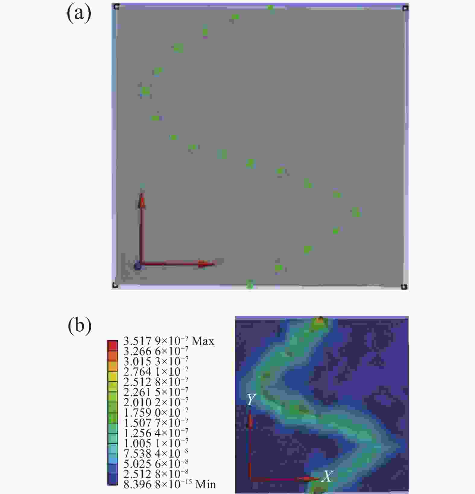
Figure 2. (a) Slide object trajectory;(b) Strain field distribution of silica gel block
图2(a)为预设的物体运动轨迹,该轨迹上半段为曲线运动,下半段为直线运动。从图2(b)中的仿真结果可以清晰地分辨出物体的曲线与直线运动轨迹。由仿真结果可知,硅胶受力后在x轴及z轴存在一定的位移变形量,有实验表明,当硅胶厚度为1.5 mm时其沿x轴的变形量最大,约为0.3 μm,因此上层硅胶选用1.5 mm的厚度。如图2(b)所示,硅胶块在受到应力时,发生变形较大的区域分别是硅胶块边缘区域为3.5×10⁻⁴ μm以及物体运动轨迹中心处为2.6×10⁻⁴ μm。
-
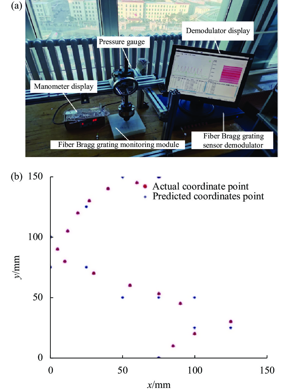
滑觉传感标定实验系统如图3(a)所示,该实验系统主要由解调仪、传感模块、压力计组成。解调仪最小分辨率为0.5 pm。实验中所用光源波长解调范围为1525~1565 nm,最小分辨率为0.5 pm。实验施力物体为一半径2 mm的金属施力杆,受力面尺寸较小,可看作点施力。硅胶块内铺设的FBG写入了8个不同峰值的光栅,每一个光栅长度为10 mm,光栅间距为8 cm,每一个光栅的反射率都能达到90%以上,且边模抑制比都大于15 dB。8个光纤光栅传感器带宽均为0.195 nm,其中光纤弹光系数、光纤热光系数分别为0.120、0.275,泊松比为0.17。

Figure 3. (a) Calibration experiment device; (b) The actual points and the predicted points of the static object position
实验过程中分别在36个小区域处施加20 N的力,反复多次进行实验,通过解调仪采集回36组光纤光栅中心波长偏移量值,用MATLAB对实验数据进行拟合,得到每一个光纤光栅传感器在每一个区域处的分辨率值,完成对光纤光栅传感模块的标定。表1为标定实验所得每一个光纤在每一个小区域处的分辨率k。
k/nm Area 1 Area 2 Area 3 Area 4 Area 5 Area 6 Area 7 Area 8 Area 9 FBG1 0.06 0.48 1.92 0.36 0.44 0.29 0.45 1.93 1.07 FBG2 0 0.01 0.54 0.32 0.09 0.76 0.29 0.84 0.45 FBG3 0 0.26 −0.37 0 0 0 0 0 0 FBG4 0.26 0.35 −0.97 −0.46 0.02 0 0 0 1.95 FBG5 0 0 −0.36 0 0.07 −0.46 0 0 0.39 FBG6 0 −0.17 −0.23 0 0 0 0 0 0 FBG7 0 −0.48 −0.20 9 10 0.74 −0.02 −0.04 0 FBG8 0.36 1.96 0.01 −0.19 −0.04 0 0 −0.07 0.04 Table 1. Different resolution values of different FBG in different regions
按照仿真图中的轨迹点用金属施力杆模拟静止物体,使其对硅胶块施加20 N的力得到如图3(b)所示的实际坐标点与预测坐标点对比图,可见以该实验标定的各个FBG响应区域能够较准确地判断物体位置坐标。
-
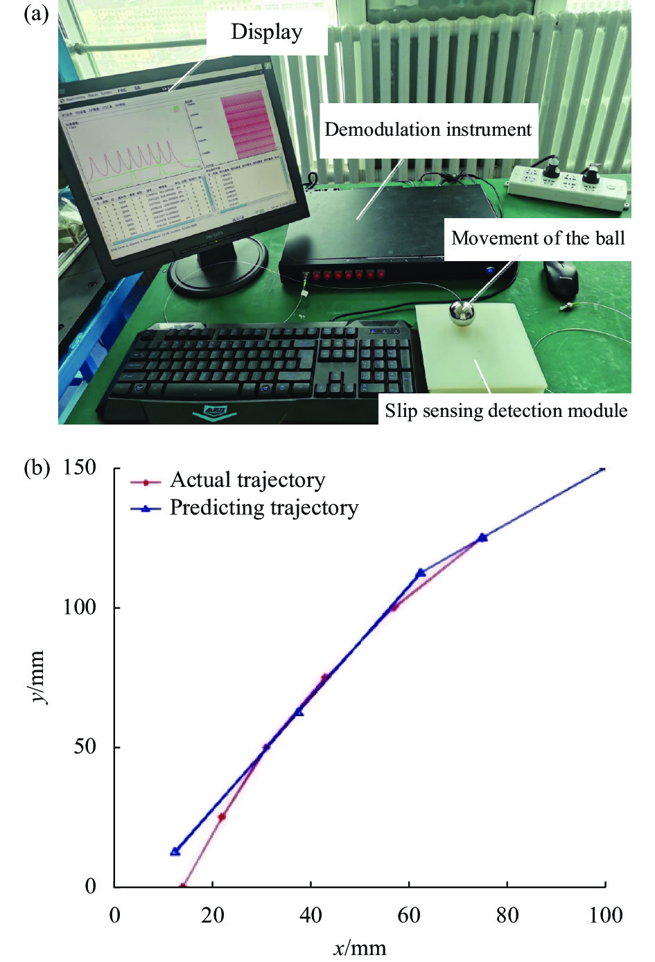
在实际轨迹监测实验中所用运动物体为0.255 kg的钢制小球,实验装置如图4(a)所示。假设物体移动过程中对硅胶作用力集中于点,给物体一定的初速度并使物体任意运动一段轨迹。物体在不断移动的过程中,对硅胶块的不同位置施加相同的力,使硅胶块发生一定的形变。与此同时,光纤光栅传感器产生相应的响应,通过解调仪记录物体移动时间以及光纤光栅中心波长实时偏移量。以公式(5)为依据,对获得的光纤光栅中心波长偏移量进行数据处理,获得铁球运动过程中实际位置坐标与预测坐标间对比图,如图4(b)所示。

Figure 4. (a) Experimental installation of monitoring small ball sports trajectory; (b) Actual trajectory comparison and measurement of small ball sports
结合标定实验与小球实验结果可知,对硅胶传感模块施加不同大小的力只是改变光纤光栅传感器响应范围以及信噪比。质量越大,压力越大,则传感器相应范围更广,其信噪比更好。由于文中是通过FBG间响应参数比值进行位置解算,即使重物的质量发生改变也不会对传感模块的解算精度产生影响。实验对质量为0.255 kg的小球进行监测,光纤光栅传感器已具有很理想的响应结果,足以证实该传感模块可应用到仿生体滑觉监测系统中。
图4(b)中红色为实际运动轨迹点,蓝色为预测运动轨迹,可以看出,以6×6来划分硅胶块,通过光纤光栅传感器的实时监测能够较准确地确定物体运动的大致路线,因此该传感组能够用来监测物体的非线性运动轨迹以及运动方向。
-
小球运动轨迹实验中选取7个点,确定每一个点所处区域以及具体位置坐标,并求得实际位置与测量位置间的距离误差,如表2所示。
Actual location/mm Section number Measuring position/mm Section number Range error/mm (14,0) A11 (12.5,12.5) A11 12.5 (22,25) A11 (12.5,12.5) A11 15.7 (31,50) A23 (37.5,62.5) A23 14 (43,75) A23 (37.5,62.5) A23 13.6 (57,100) A35 (62.5,112.5) A35 13.6 (75,125) A45 (87.5,137.5) A45 17.6 (100,150) A55 (100,150) A55 0 Table 2. Ball trajectory and prediction trajectory
实际点与测量点间的距离误差为:
实际点与测量点间的角度误差为:
由计算结果可知,运动过程中小球实际运动位置与该系统预测位置距离最大误差为17.6 mm,该系统预测的小球的区域位置与实际区域位置完全一致,而位置误差大小均小于所划分区域数值大小。由最后的实验结果可知,在将光纤传感模块划分为6×6的分辨率的情况下,可以较准确地确定物体的具体位置和运动方向,并且系统在位置角度的测量过程中可以通过调节FBG铺设密度来实现更准确的测量。如果想要更进一步提高位置坐标的准确度,可以以同样的粘贴方式增加FBG的数量或者划分成更小的区域。由于光纤光栅传感器是嵌入到硅胶中,在实际应用中可根据测量现场具体问题对硅胶的形状、大小以及厚度进行调整,实现了某些特定测量场合对传感器微型化的要求。
-
文中利用光纤光栅传感器监测物体的滑动,对光纤光栅传感组结构设计进行优化,建立了新型滑觉感知系统。仿真和实验结果表明,光纤传感模块中最大敏感位置的平均形变量约为0.32 μm,且传感模块可准确无误地确定物体所在区域位置。目前大多数光纤光栅触觉传感器只解决单个触觉或者滑觉问题,或者是如何区别触觉与滑觉问题,而文中则是重点解决当物体存在滑觉时,监测物体实时的运动状态问题,并且完成了对滑动物体运动轨迹的监测,该传感模块有望运用到仿生体的滑觉智能传感领域。
On-line slippage measurement system for optical fiber sensing array
doi: 10.3788/IRLA20210278
- Received Date: 2021-04-28
- Rev Recd Date: 2021-06-23
- Publish Date: 2022-04-07
Fund Project:
National Natural Science Foundation of China (61703056);Key research and development projects of medical devices in Jilin Province(20220204106YY)
-
Key words:
- fiber Bragg grating sensor /
- displacement monitoring /
- state analysis /
- perception array /
- simulation analysis
Abstract: Aiming at the real-time monitoring of position and velocity in smart flexible sliding sensor, a fiber optic sensing module for real-time monitoring of target displacement and velocity was designed. First, the temperature compensation module was used to solve the temperature cross-sensitivity problem; then, based on the analysis of the stress distribution simulation results of the sensing unit, the "meter" type FBG network structure was proposed; finally, the standard pressure gauge and the ball were used to complete the test of the position direction and the speed state, and a target state solution model suitable for this structure was proposed. The simulation results show that the average deformation of the target trajectory is about 0.32 μm, and the attenuation distance width is about 3.0 mm. The experiment carried out a sliding test on a 0.255 kg steel ball. The FBG stress sensitivity was better than 0.0206 nm/N. The FBG center wavelength offset can accurately determine the location of the object and the direction of the object's movement. The sensor module can monitor the movement state of the object in real time, and intelligently adjust the force and posture of the object. The results show that the plane positioning accuracy, motion angle and speed conversion of the sliding sensor system meet the design requirements, and according to the model function relationship, it can be known that the control of accurancy of the position, angle and speed can be achieved when adjusting the total amount of FBG in the sensor network. In summary, the system has the capability of real-time monitoring of the target position and movement status in the detection area, and is suitable for technical fields such as flexible intelligent assembly and intelligent bionic skin.


 DownLoad: