


-
土体水分场反规律性变化是山体滑坡[1]、泥石流[2]、洪水[3]等重大自然灾害发生的激发条件之一,准确获取土体水分场的变化信息能够对可能发生的自然灾害提前预警,避免造成重大人员伤亡和经济损失。此外,土体水分场也是岩土工程地质评价[4]、农业精准灌溉[5]、区域水文条件研究[6]的重要影响因子。
目前测量土壤水分含量有很多种方法。烘干法是国际公认的土壤水分含量检测方法,但需要从室外取土,这一过程中会破坏土体本身构造,耗用时间长,一般适用于实验室测量或对其他测量方法进行标定[7];时域反射法易受干扰且结构复杂,价格昂贵[8];张力计法稳定性能低,且易被土壤理化特性影响,难以实现连续原位监测[9];电阻法容易受到土壤盐分、质地、孔隙分布等因素的影响,标定复杂[3];中子法标定过程存在误差,且有放射性危害[10];探地雷达法适合于大面积场所的水分含量探测,但解译难度大,受电导率影响显著[6];遥感法多用于大范围土壤水分宏观估测,而不适合小区域精准测量[11]。
光纤传感技术具有体积小、质量轻、耐腐蚀、本质安全、传输距离远、易于大规模组网等突出优点,近年来在电力、化工、矿山、军事等领域得到广泛应用[12-17]。在土壤水分含量测量方面,2015年曹鼎峰等人提出了一种基于碳纤维加热光缆的分布式测定方法,加热过程需要外加电源,功率消耗大[6];2017年 J.S.Hallett 等人利用长周期光纤光栅设计了一种土壤含水量传感器,但不适用于测量低含水率[18]。针对上述测量方法的不足,结合光纤传感的优异性能,文中基于掺杂光纤的光热转换效应和光纤光栅测温原理研发了一种全光纤微型土壤水分含量传感器,可实现土壤水分含量的远距离在线监测,特别适合野外等取电困难的应用场合。
-
全光纤微型土壤水分含量传感器的测量原理是:土壤水分含量不同会导致其热传导性能发生变化,含水率越高,其热传导能力越强。将具有自加热和测温功能的微型光纤传感探头置于待测土壤中,探头内的掺杂光纤将泵浦激光能量转换成热能,实现光热转化。并通过刻写在掺杂光纤上的光纤Bragg光栅测量探头的温度变化,利用升温过程中温度特征值与土壤含水率之间的关系可测定土壤水分含量。
假设待测土样为均质且各项同性,可以将土壤内部热传递视为一维问题[6]。在单位时间内,单位长度光纤在泵浦光作用下产生的热量为:
式中:
$ p_0 $ 表示光纤入射端的初始光强;$ \alpha $ 表示光纤对泵浦光的吸收系数;${\rm{e}}$ 表示自然对数的底数;$ l $ 表示光纤长度;$ k $ 表示光热转化系数。散失的热量为:
式中:
$ \lambda $ 为导热系数,与土体自身性质相关;$\dfrac{{\partial T}}{{\partial n}}{\vec {{n}}_0}$ 为温度梯度。则实际用于加热光纤的热量表示为:
式中:
$ c $ 为热源比热容;$ m $ 为热源质量;$ {T_0} $ 为加热前光纤的初始温度;$ T $ 为加热后光纤温度;$ \Delta T_t = T - T_0 $ 定义为温度特征值,表示加热后土体热量扩散程度。将公式(1)~(3)联立推导出土体导热系数$ \lambda $ :当温度场稳定后,待测土体各项同性且均匀,温度梯度
$\dfrac{{\partial T}}{{\partial n}}{\vec {{n}}_0}$ 为常数,公式(4)可简化为:土体导热系数
$ \lambda $ 为水溶液导热系数$ \lambda_{\rm{w}} $ 和固体导热系数$ \lambda_{\rm{s}} $ 之和(气体导热系数可忽略),即当温度场达到稳定,土体间相邻位置的固体与液体等温,相互热传递可忽略。其中
$ \lambda_{\rm{w}} $ 与土样含水率$ w $ 呈正相关关系:$ {\lambda _{\rm{w}}} = aw $ ,则土样含水率为:式中:
$ {k_1}{\text{ = }}{k_0}/a $ 为水温转换系数;${b_1}{\text{ = }} - {\lambda_\rm{s}}/a + {b_0}/a$ 为水温修正系数。可见温度特征值$ \Delta {T_t} $ 与含水率$ w $ 呈线性关系,利用该关系可进行土体含水率定量测定。 -
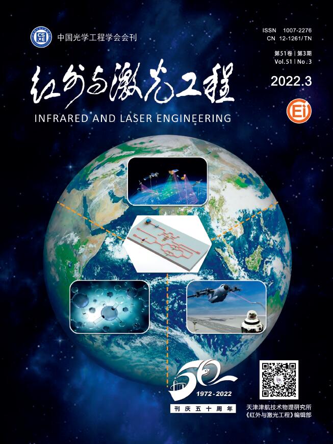
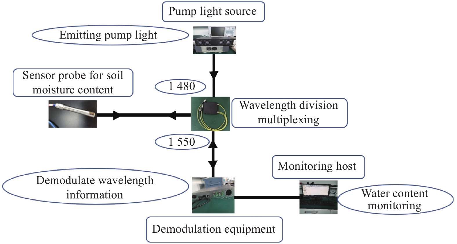
全光纤土壤水分含量传感系统(图1)包括泵浦光源、传感探头、波分复用器(Wavelength Division Multiplexing, WDM)、光纤光栅解调模块、数据处理模块等。1480 nm的泵浦光用于对传感探头内部掺杂光纤加热,光纤光栅解调模块发射1550 nm的脉冲激光,同时接收解调光纤光栅的反射信号。WDM将泵浦光和解调模块发射光合光接入到传感探头,掺杂光纤内的钴离子吸收泵浦光能量从基态跃迁到激发态,再通过非辐射跃迁(多声子驰豫)过程将激光能量转换成热能,实现光热转化[19],引起光纤本身温度升高,进而导致掺杂光纤内部Bragg光栅中心波长偏移,光栅反射信号通过WDM进入解调模块,由解调模块解算出该波长偏移[20]。然后再由数据处理系统实时读取解调模块内的波长信息,解算为实际温度数据,并计算出温度特征值,最后根据温度特征值与土壤含水率之间的线性关系(公式7)计算出需要测量的土壤水分含量。
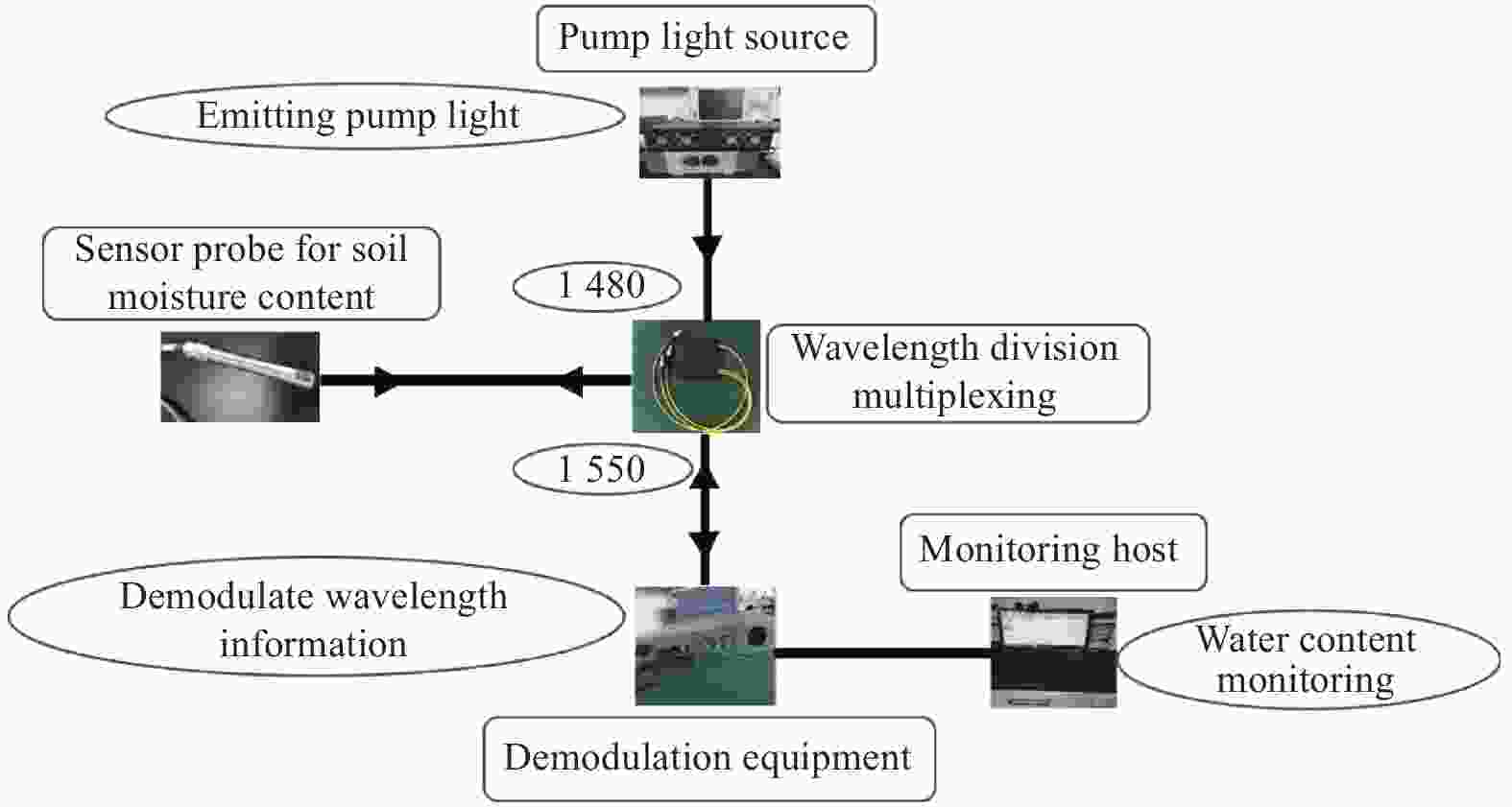
Figure 1. Sensing system structure diagram
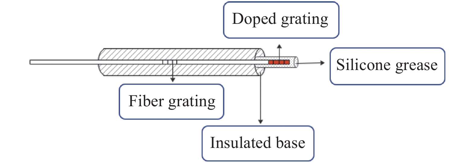
图2为全光纤土壤水分含量传感器探头结构。刻写在掺杂光纤上的光纤Bragg光栅用来测量加热过程中掺杂光纤的温度变化,在不同含水率土壤中掺杂光纤的温度变化情况不同。掺杂光纤温度变化,进而引起光纤光栅的反射光中心波长发生偏移。通过精确测量光栅的中心波长即可准确反演出土壤含水率。为消除环境温度变化造成的含水率测量误差,探头后端设置了一只普通测温光栅,用于反映土壤自身温度变化。

Figure 2. Probe structure of all optical fiber soil moisture content sensor
-
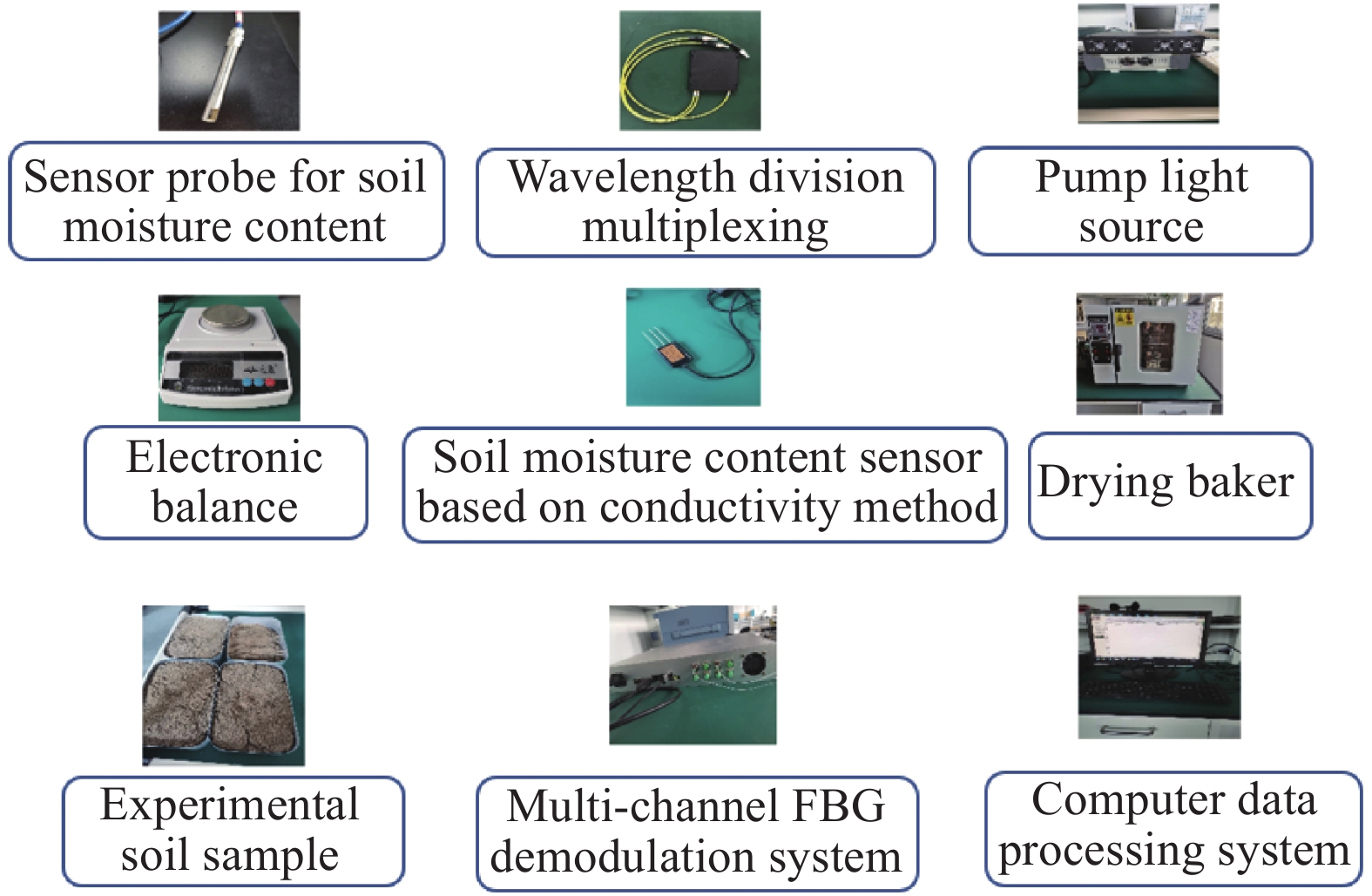
为了验证上述传感系统的可行性,并对系统技术指标进行标定和测试,搭建了土壤水分含量测试平台,图3为测试平台基础配置图,主要由全光纤土壤水分含量传感系统、实验土样、烘干机、电子称重仪、基于电导率法的土壤含水率传感器(作为参考)等组成。各模块技术规格见表1。实验用传感探头内部为高浓度掺钴光纤光栅(长度为8 mm,泵浦光吸收率约为38%)和普通测温光纤光栅,为减小掺杂光纤热量传导引起普通光栅的测量误差,实验中将二者间距保持20 mm,同时增设了隔热底座。
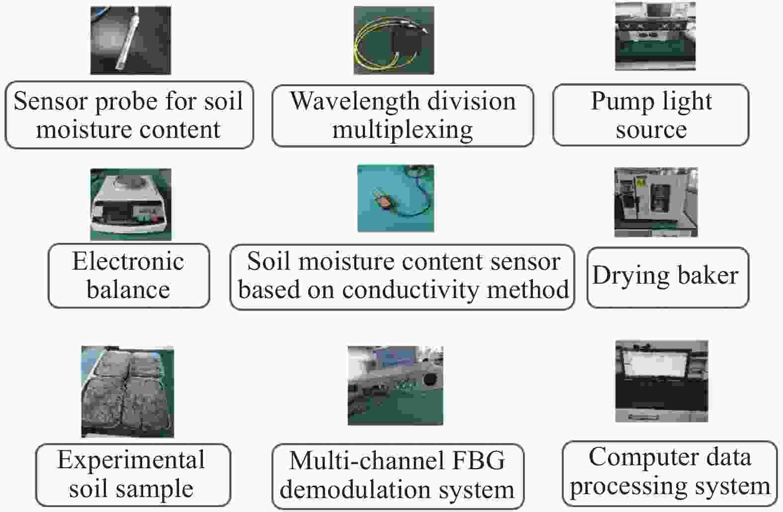
Figure 3. Basic configuration diagram of the experimental
Parameter Value Probe material Stainless steel Soil type Sand/Loess Pump light source wavelength 1480 nm Demodulator model GC-97001C Pump light heating power 450 mW Electronic weighing instrument accuracy 0.001 g Drying box temperature/heating time 120 ℃/12 h Doped Bragg grating center wavelength 1550.038 nm Reference grating center wavelength 1539.870 nm Table 1. Parameters of soil moisture content test platform
-
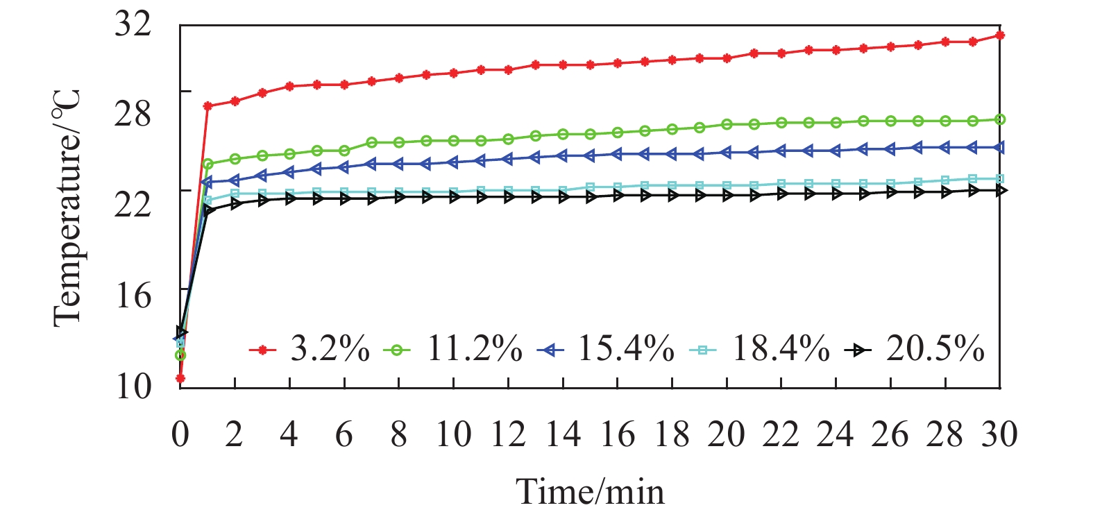
将全光纤传感探头埋于五组水分含量逐级递增的实验土样中,鉴于土壤的热传导性能易受土壤颗粒大小、干密度等因素影响,实验采用粒径1 mm、干密度基本一致的砂性土样,饱和含水率为23.87%。设定泵浦功率为450 mW对传感探头加热,实验时长为30 min,每间隔1 min取一个温度采样点,则每组土样得到30个采样数据。测量结束后用烘干法测得土样含水率分别为3.2%、11.2%、15.4%、18.4%、20.5%。图4所示为在不同含水率土壤中传感探头温度随加热时间的变化情况。可以看出,开始加热后,传感探头在不同含水率土壤中温度均呈现上升趋势,开始2 min传感探头快速升温,处于不稳定状态,温度升高速率随着土壤含水率增加呈减小趋势。2 min后传感探头升温过程逐渐趋于稳定。土壤含水率越低,温度特征值越高。
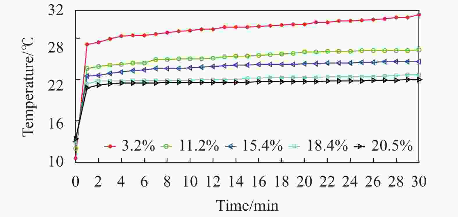
Figure 4. Change of soil moisture probe temperature with time
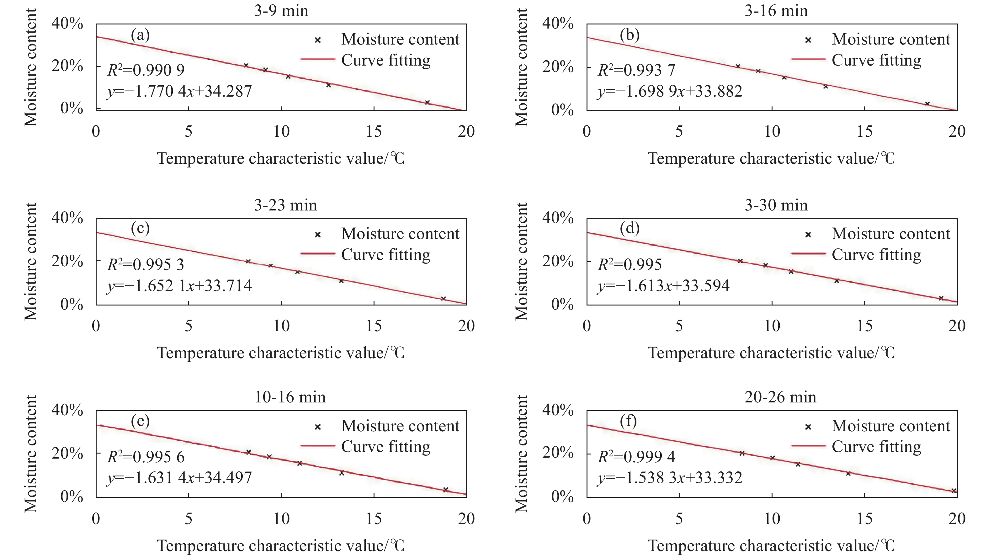
选择3~9 min、3~16 min、3~23 min、3~30 min、10~16 min、20~26 min时间段,得到土壤含水率和对应的温度特征值的拟合曲线,如图5所示。可以看出,各时间段土壤含水率与温度特征值呈线性关系,温度特征值随着土壤含水率增大而减小。3~9 min时间段的拟合度比其他时间段略低,随着温度特征值逐渐趋于稳定,线性关系斜率逐渐减小,相关系数逐渐提高,20~26 min时间段相关系数最好,达到0.9964。这说明取实验中后期时间段的测量结果更精准,初始时间段测量结果可用于土壤水分含量快速测量。

Figure 5. Temperature characteristic value fitting curve
-
为了进一步验证全光纤微型土壤水分含量测量传感器的可行性和精确性,选取五组含水率未知,土壤直径和干密度相同的砂性土壤,分别用烘干法、全光纤微型土壤水分含量传感器和电子土壤水分传感器测量土壤样本的含水率,进行对比实验,测量结果如表2所示。以烘干法测量结果作为基准,光纤传感器的最大测量误差−1.41%,基于电导率法的土壤含水率传感器的测量误差整体偏大,最大误差达到2.90%。可见相比于基于电导率法的土壤含水率传感器,全光纤微型土壤水分含量传感器测量误差更小,可以满足岩土工程模型试验、农业精准灌溉等实际应用中对含水率的测量需求。
Drying method Fibe r method Electronic method Value Error Val ue Err or 3.1% 4.26% 1.16% 5.3% 2.20% 6.5% 6.99% 0.49% 8.9% 2.40% 14.4% 12.99% −1.41% 15.6% 1.20% 15.6% 15.4% −0.20% 18.3% 2.70% 17.5% 18.28% 0.78% 20.4% 2.90% Table 2. Results of different moisture content measurement methods
-
将传感器探头置于含水率为21.3%的砂性土样中,选择温差较大的时间段,实验时长为6 h,每间隔10 min记录含水率测量值,图6为温度补偿前后土壤水分含量测量误差对比图。可以看出,土壤温度变化对传感器的检测精度影响较大,在未进行温度补偿时,传感器的最大测量误差可达−2.51%,利用参考光栅进行温度补偿后,测量误差明显减小,整体误差可控制在±0.5%以内,基本消除了昼夜温差或季节变化等因素对测量结果的影响。
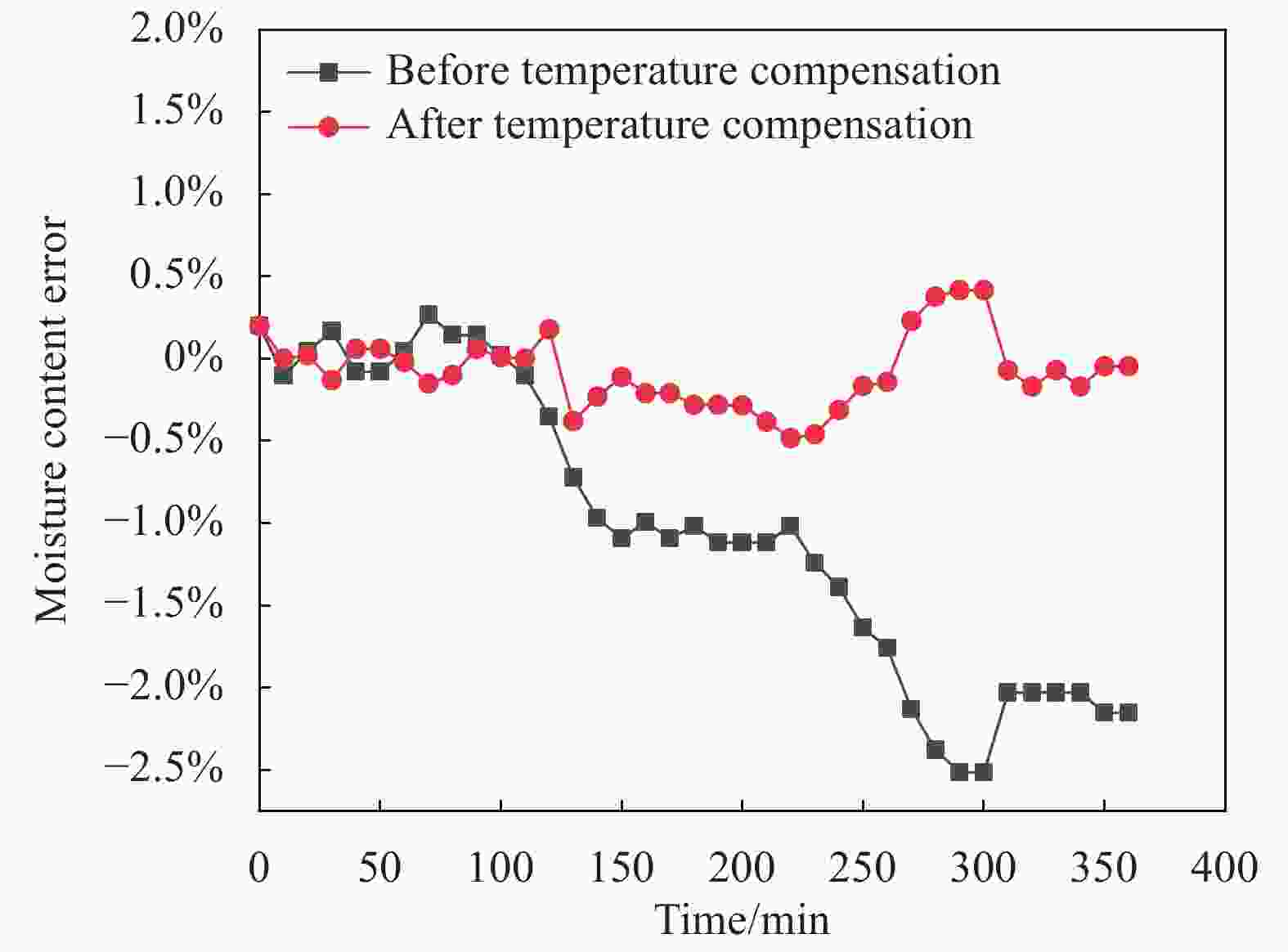
Figure 6. Comparison of measurement errors of soil moisture content before and after temperature compensation
-
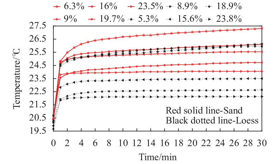
选择含水率不同的砂土土样和黄土土样各五组,保持土壤密实度不变,设定泵浦功率为450 mW,测量时长30 min,通过全光纤土壤水分含量传感器测得砂土土样和黄土土样中探头温度变化如图7所示。可以看出,在土壤含水率相似的不同类型土样中,传感探头的温度变化差异较大,则温度特征值与含水率之间的率定关系(公式7)也存在差异。因此,传感器在实际使用时需要提前标定土样:将含水率作为唯一变量,测量不同梯度水分含量土壤的温度特征值,将各级含水率
$ w $ 与对应的温度特征值$ \Delta {T_t} $ 进行拟合,即可标定得到该类型土体的水温转换系数$ {k_1} $ 和水温修正系数$ {b_1} $ 。
Figure 7. Temperature variation diagram of sensing probe in different types of soil samples
-
文中采用掺杂光纤作为加热元件,光纤光栅作为测温元件,研发了一种全光纤微型土壤含水率传感器,根据土壤温度特征值和含水率的线性关系可实现土壤含水率的在线原位监测。该传感器敏感部件和传输介质均为光纤,无需外加电源,同时具备环境温度补偿功能,适用于工作环境复杂且取电困难的野外场所。实验表明:传感器所测土壤含水率与烘干法具有较好的一致性,最大误差−1.41%,满足农业生产和工业安全等领域对实际应用中水分含量的测量要求;另外,对不同类型及密实度差异较大的土样,该传感器的水温转换系数、水温修正系数存在差异,实际使用中需要提前标定。下一步将开展不同土样的灵活定标、环境温度自适应补偿等技术研究,进一步提升该技术的准确性和实用性。
All-optical fiber miniature soil moisture content sensor
doi: 10.3788/IRLA20210299
- Received Date: 2021-05-10
- Rev Recd Date: 2021-09-17
- Publish Date: 2022-04-07
Fund Project:
Natural Science Foundation of Shandong Province - Youth Foundation(ZR2020QF088);Natural Science Foundation of Shandong Province(ZR2020KC012)
-
Key words:
- all-optical fiber soil moisture content sensor /
- light-to-heat conversion /
- in-situ measurement
Abstract: Based on the photothermal conversion effect of doped fiber and the principle of Fiber Bragg Grating (FBG) temperature measurement, an all-fiber miniature soil moisture content sensor was developed. The 1480 nm pump laser was used to heat the cobalt-doped fiber embedded in the soil, and the temperature change was measured by the Bragg grating engraved on the cobalt-doped fiber. The in-situ measurement of soil moisture content was realized according to the linear relationship between temperature characteristic value and moisture content in the heating process. In order to verify the feasibility of this method and the accuracy of the sensor, a soil moisture content test platform was built and experiments were carried out. The experiments show that there is a linear relationship between the characteristic value of temperature and soil moisture content; the soil moisture content measured by the all fiber micro soil moisture content sensor is in good agreement with the drying method, and the maximum error is −1.41%, which is obviously better than the conductivity method. This new type of soil moisture content measurement method has the characteristics of miniaturization and low power consumption.


 DownLoad: