


-
基于磁光调制的通视方位传递技术要求携带方位信息的偏振光必须沿直线传播且无遮挡,对此提出了基于保偏光纤的新型非通视方位传递技术[1],在原有基础上,借助保偏光纤理论上能够实现非通视条件下方位信息的传递,该技术在航天器发射初始对准、仪器测量及隧道工程等诸多领域有着广阔的应用前景。
保偏光纤应用广泛,如偏振控制、光纤传感和相干通信[2-4]。按照光纤的结构分类,保偏光纤可以依据截面几何形状不同将其分为熊猫型、领结型、椭圆型等;按照双折射产生机理[5],保偏光纤可分为几何双折射和应力双折射,几何双折射保偏光纤产生机理为光纤纤芯的非圆性造成光纤两轴(
$x$ 轴和$y$ 轴)上折射率的不一致性,应力双折射保偏光纤产生机理为纤芯外部施加应力致使圆型纤芯受到非对称的拉力,引起两轴上折射率偏差。不论是几何双折射保偏光纤还是应力双折射保偏光纤,都是通过一定的方式使两轴折射率产生差异[6-8]。近年来,学者们对应力双折射保偏光纤展开了全面研究。2018年,贝勒大学设计并提出了一种高双折射保偏负曲率光纤[9],这种设计在对偏振效应敏感的光纤设备中非常有用;2020年,天津大学建立了一个用于估算熊猫型保偏光纤中应力诱导双折射的分析模型,模型的研究方案清晰简单,为文中的研究提供了关键参考[10]。此外,学者对调整保偏光纤结构以满足不同系统要求有着浓厚的兴趣[11]。2018年,上海大学提出并证明了三应力单元光纤中应力场分布的经验公式,分析了三应力单元光纤的传输特性[12]并于2020年详细研究了三扇形应力单元光纤的应力分布特性,通过参数调整,优化确定了圆偏振态稳定传输的光纤结构[13]。2019年,哈尔滨工程大学提出了一种新型应力诱导保偏光纤,并进行了模式场性能分析[14]。2019年,华中科技大学设计了一种熊猫型四芯光纤,光学特性优异[15]。非通视方位传递系统中重点关注相位差引起的方位角变化,对于应力型保偏光纤而言,应力双折射与相位差直接密切相关。文中从非通视方位传递系统原理出发,根据热应力和平面应力应变关系,推导保偏光纤折射率表达式,详细分析了熊猫型保偏光纤不同参数与双折射值之间的关系,对比分析了领结型保偏光纤的光学性能。
-
图1所示为基于保偏光纤的非通视方位传递系统,上、下仪器分别安装在非通视位置,两仪器利用保偏光纤连接。上仪器中激光器发出的激光经过起偏器成为线偏振光,携带起偏器方位信息的线偏振光耦合进入保偏光纤,并传输至下仪器的调制器中。偏振光通过调制器内部磁光材料时,在调制信号驱动产生的交变磁场作用下,实现了偏振光信号的调制。调制后的偏振光信号经过检偏器、聚焦镜、光电转换、信号检测处理等,提取出与方位角对应的电信号,并驱动下仪器转动,完成方位同步,实现非通视条件下方位信息传递。非通视方位传递系统中,保偏光纤双折射直接决定相位差精度,进而影响方位传递精度,因此重点分析保偏光纤的双折射。

Figure 1. Schematic diagram of non-line-of-sight azimuth transmission system based on polarization-maintaining fiber
从系统原理出发,非通视方位传递系统对保偏光纤双折射的设计要求为:有限元仿真结果得到数量级处于108的应力张量分量,且通过进一步计算后熊猫型保偏光纤双折射值处于
$3.55 \times {10^{ - 4}}$ ~$5.32 \times {10^{ - 4}}$ 范围内时,即可说明达到系统对双折射的要求。运用有限元方法对熊猫型保偏光纤和领结型保偏光纤求解之前,需要了解保偏光纤制作的基本流程,充分把握制作流程才能选用准确的物理过程借助有限元分析软件进行模拟,使得建模仿真与真实的物理过程尽可能地保持一致。当有限元分析结果达到双折射要求,进一步开展的研究才能求解出对保偏光纤设计有实际参考的仿真结果,保证仿真分析结果可靠。
假设保偏光纤沿传播方向是均匀的,传播方向上单位长度的应变能[16-18]为:
式中:
${\rm{d}}x$ 、${\rm{d}}y$ 表示光纤横截面上的积分;${{T}}$ 表示应力矢量;${\boldsymbol{\varepsilon}} $ 表示应变矢量。当保偏光纤结构在
${\textit{z}}$ 方向上的尺寸远大于$x$ 和$y$ 两个方向上的尺寸,且施加的力作用在$x - y$ 平面上,并在$z$ 方向上没有变化时,应力-应变关系为:其中,
$[c] = \left[ {\begin{array}{*{20}{c}} {\dfrac{{(1 - v)E}}{{(1 + v)(1 - 2v)}}}&{\dfrac{{vE}}{{(1 + v)(1 - 2v)}}}&0 \\ {\dfrac{{vE}}{{(1 + v)(1 - 2v)}}}&{\dfrac{{(1 - v)E}}{{(1 + v)(1 - 2v)}}}&0 \\ 0&0&{\dfrac{E}{{2(1 + v)}}} \end{array}} \right]$ ${{T}} = \left[ {\begin{array}{*{20}{c}} {{\sigma _x}} \\ {{\sigma _y}} \\ {{\sigma _{xy}}} \end{array}} \right]$ ,${\boldsymbol{\varepsilon}} = \left[ {\begin{array}{*{20}{c}} {{\varepsilon _{xx}}} \\ {{\varepsilon _{yy}}} \\ {2{\varepsilon _{xy}}} \end{array}} \right]$ ,${{\boldsymbol{\varepsilon}} _0} = \left[ {\begin{array}{*{20}{c}} {(1 + v)\alpha \Delta T} \\ {(1 + v)\alpha \Delta T} \\ 0 \end{array}} \right]$ 。式中:$E$ 为杨氏模量;$\nu $ 为泊松比;$\alpha $ 为热膨胀系数;$\Delta T$ 为温度变化;${\sigma _x}$ 、${\sigma _y}$ 为正应力;${{\boldsymbol{\varepsilon}} _0}$ 为初始应变;${\varepsilon _{xx}}$ 、${\varepsilon _{yy}}$ 为正应变;${\varepsilon _{xy}}$ 和${\sigma _{xy}}$ 分别为剪切应变和应力。应变-位移关系为:式中:
${\nabla _\varepsilon } = \left[ {\begin{array}{*{20}{c}} {\begin{array}{*{20}{c}} {{\partial / {\partial x}}} \\ 0 \\ {{\partial / {\partial y}}} \end{array}}&{\begin{array}{*{20}{c}} 0 \\ {{\partial / {\partial y}}} \\ {{\partial / {\partial x}}} \end{array}} \end{array}} \right]$ ;${{u}} = \left[ {\begin{array}{*{20}{c}} {{u_x}} \\ {{u_y}} \end{array}} \right]$ ,${u_x}$ 和${u_y}$ 分别为位移${{u}}$ 的$x$ 和$y$ 分量,整理公式(1)~(3)可得:光纤横截面划分成许多线性三角形单元后,将每个单元中的位移
${{u}}$ 展开:式中:
${\left\{ {{u}} \right\}_e} = \left[ {\begin{array}{*{20}{c}} {{{\left\{ {{{{u}}_{{x}}}} \right\}}_e}} \\ {{{\left\{ {{{{u}}_{{y}}}} \right\}}_e}} \end{array}} \right]$ ;$\left[ {{N}} \right] = \left[ {\begin{array}{*{20}{c}} {\left\{ {{N}} \right\}}&{\left\{ 0 \right\}} \\ {\left\{ 0 \right\}}&{\left\{ {{N}} \right\}} \end{array}} \right]$ ;${\left\{ {{{{u}}_{{x}}}} \right\}_e}$ 和${\left\{ {{{{u}}_{{y}}}} \right\}_e}$ 为节点位移矢量;$\left\{ {{N}} \right\}$ 为形状函数矢量;$\left\{ 0 \right\}$ 为零矢量。假设每个单元初始应变恒定,根据变分原理可以得到:式中:
$\left[ K \right] =\displaystyle \sum\limits_e {\iint_e {\left[ B \right]}} \left[ c \right]{\left[ B \right]^{\rm{T}}}{\rm{d}}x{\rm{d}}y$ ,$\left\{ {{f}} \right\} = \displaystyle\sum\limits_e {\iint_e {\left[ B \right]}} \left[ c \right] $ ·$ {{{\varepsilon}} _0}{\rm{d}}x{\rm{d}}y $ ,$\left[ B \right] = \left[ {\begin{array}{*{20}{c}} {\begin{array}{*{20}{c}} {\left\{ {{{{N}}_{{x}}}} \right\}}\;\;{\left\{ 0 \right\}}\;\;{\left\{ {{{{N}}_{{y}}}} \right\}} \end{array}} \\ {\begin{array}{*{20}{c}} {\left\{ 0 \right\}}\;\;{\left\{ {{{{N}}_{{y}}}} \right\}}\;\;{\left\{ {{{{N}}_{{x}}}} \right\}} \end{array}} \end{array}} \right]$ 。应力型保偏光纤中,纤芯和包层的不同热膨胀系数将导致热应力,从而在光纤中引入双折射。遵循应力光弹效应,使用张量:
式中:
${n_{ij}}$ 为材料的折射率,存在$\Delta {n_{ij}} = {n_{ij}} - {n_0}{I_{ij}}$ ,${I_{ij}}$ 为单位张量;${B_{ijkl}}$ 为应力光学张量;${S_{kl}}$ 为应力张量,也称为应光系数。由于保偏光纤的对称性,
${n_{ij}}$ 和${S_{kl}}$ 都是对称的,因此存在${B_{ijkl}} = {B_{jikl}}$ ,${B_{ijkl}} = {B_{jilk}}$ 。可进一步简化为${B_1}$ 和${B_2}$ ,${B_1}$ 为第一应力光学系数,${B_2}$ 为第二应力光学系数。因此公式(8)简化为:式中:
${n_x} = {n_{11}}$ 、${n_y} = {n_{22}}$ 、${n_{\textit{z}}} = {n_{33}}$ 分别表示$x$ 、$y$ 、$z$ 三个单位方向上的折射率;${S_x} = {S_{11}}$ 、${S_y} = {S_{22}}$ 、${S_z} = {S_{33}}$ 分别表示$x$ 、$y$ 、${\textit{z}}$ 三个单位方向上的正应力。依据公式(9)可得:假设
${n_{ij}}$ 的非对角部分忽略不计。将公式(10)两两作差可得:式中:
$c$ 为对应的保偏光纤材料相对应力光弹系数,存在$c = {B_2} - {B_1}$ 。 -
根据构建的应力光学模型,利用仿真软件对熊猫型保偏光纤的双折射进行重点分析,并对领结型保偏光纤进行了对比分析。
-
非通视方位传递系统的光源波长为
${\rm{532 }}\;{\rm{nm}}$ 。初步考虑选用的熊猫型保偏光纤截面结构如图2所示,纤芯半径$r1 = 2 $ μm,应力区半径$r3 = $ 13.5 μm,包层半径$r2 = 50 $ μm,纤芯中心和应力区中心距离$d\_cs = 22$ μm。详细参数如表1所示。
Figure 2. Cross-section of Panda polarization-maintaining fiber
Parameter Core Clad Saps Refractive index 1.443 1.431 1.427 Young’s modulus/GPa 78.3 72.5 28.6 Poisson’s ratio 0.186 0.452 0.193 Density/kg·m−3 2 203 2 203 2 380 Thermal expansion 6.4e-7 5.4e-7 37e-7 First stress factor/m2·N−1 - 0.65e-12 - Second stress factor/m2·N−1 - 4.2e-12 - Working temperature/℃ - 20 - Reference temperature/℃ - 1 000 - Table 1. Material parameters of Panda polarization-maintaining fiber
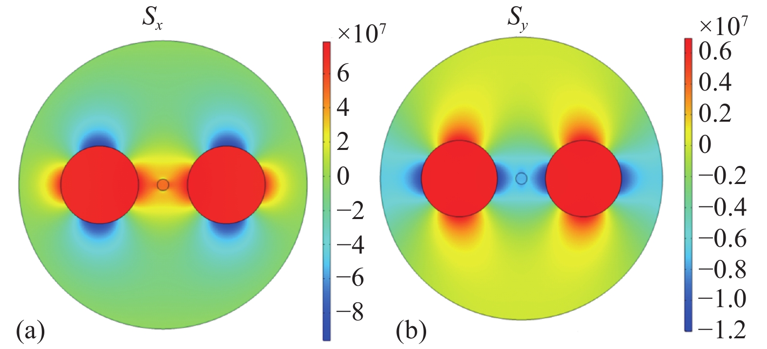
通过几何建模、材料定义、物理场设置、网格划分后,初步得到局部效果见图2。图3所示为计算得到熊猫型保偏光纤的应力张量,应力区的应力张量明显大于其他区域的应力张量,同时在应力区分别衍伸出两个方向的变化趋势。图3(a)中,包含纤芯的
$x$ 方向应力张量大于$y$ 方向应力张量,(应力区分别受到$x$ 方向的正应力和$y$ 方向的负应力),图3(b)则与之相反。
Figure 3. Stress component. (a)
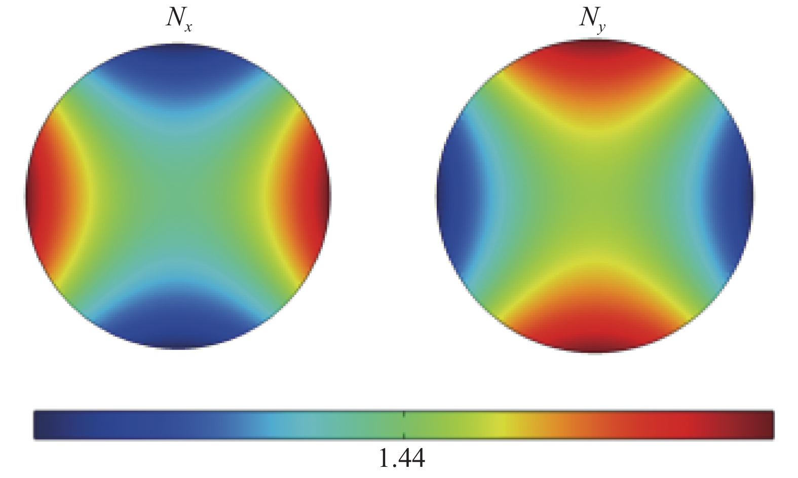
${S_x}$ ; (b)${S_y}$ 非通视方位传递系统中,方位信息传输主要聚焦于保偏光纤的纤芯,因此选定纤芯部分得到折射率分量
${N_x}$ 和${N_y}$ ,具体如图4所示。由图4可见,纤芯$x$ 方向边缘的折射率明显大于中心的折射率,$y$ 方向也有类似规律,保证了纤芯中心信息的高效传输。
Figure 4. Refractive index diagram of fiber core region
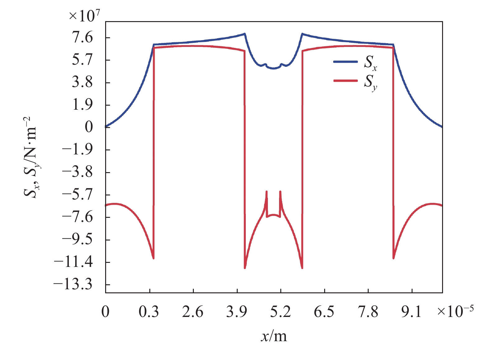
添加沿
$x$ 方向的二维截线,使二维截线依次穿过包层、应力区、纤芯,得到二维截线上应力张量分量${S_x}$ 和${S_y}$ 的二维线图,如图5所示。由图5可知:(1)二维截线上应力张量分量
${S_x}$ 全为正值,纤芯部分的数值大小为${S_x} = 5.08 \times {10^7}\;{\rm{N}}/{{\rm{m}}^2}$ ,纤芯部分的应力张量分量${S_y}$ 数值大小为${S_y} = - 7.52 \times {10^7}\;{\rm{N}}/{{\rm{m}}^2}$ ,计算可得纤芯中心处双折射为${n_B} = c({S_x} - {S_y}) = 4.473\;00 \times {10^{ - 4}}$ ;(2)根据双折射数值可知沿$x$ 轴存在拉应力,沿$y$ 轴存在压应力,当保偏光纤受到拉应力或压应力时,应力区和包层区域产生的应变不同,使纤芯区的各向异性应力改变,根据计算结果可知$x$ 方向是慢轴,$y$ 方向是快轴,与理论符合。
Figure 5. Stress component along
$x$ 为了关注纤芯区域的双折射,特别是纤芯中心部分的变化趋势,添加一组通过纤芯并且长度关于纤芯中心对称的二维截线,得到纤芯中心附近沿
$x$ 方向的折射曲线,如图6所示。
Figure 6. Birefringence curve of Panda polarization- maintaining fiber core
图6表明纤芯中心部分双折射值最低,为
$4.409\;93 \times {10^{ - 4}}$ ,中心两侧的双折射值呈对称增大,纤芯的双折射整体处于$4.410\;42 \times {10^{ - 4}}$ 左右。 -
由于保偏光纤双折射受多种因素影响,改变不同参数可以获得更好的双折射,进一步提高保偏能力。
调整纤芯与应力区的距离,得到相应的双折射值,双折射值随距离变化曲线如图7所示,在纤芯中心附近,双折射值随距离的增大而变小,同时可知纤芯与应力区的距离分别为
$d\_cs = 17 $ μm和$d\_cs = 23$ μm时,双折射数值不同,但整体变化趋势基本保持一致。熊猫型保偏光纤应力区大小影响光纤性能,是一项重要参数。增大应力区半径大小,得到双折射值随应力区半径的变化曲线,如图8所示,图中结果表明随着应力区半径增大,双折射值逐步提高。一定范围内,尽量增大应力区半径能够获得较高的双折射值,同时也应该综合考虑纤芯半径、纤芯与应力区之间的距离。熊猫型保偏光纤制备工艺复杂,为获得高双折射而引入了应力区,但是应力区温度稳定性较差,使得保偏光纤对温度较为敏感。在温度影响下,保偏光纤的折射率和双折射都会发生变化,使得光纤的保偏性能产生波动甚至总体性能下降。
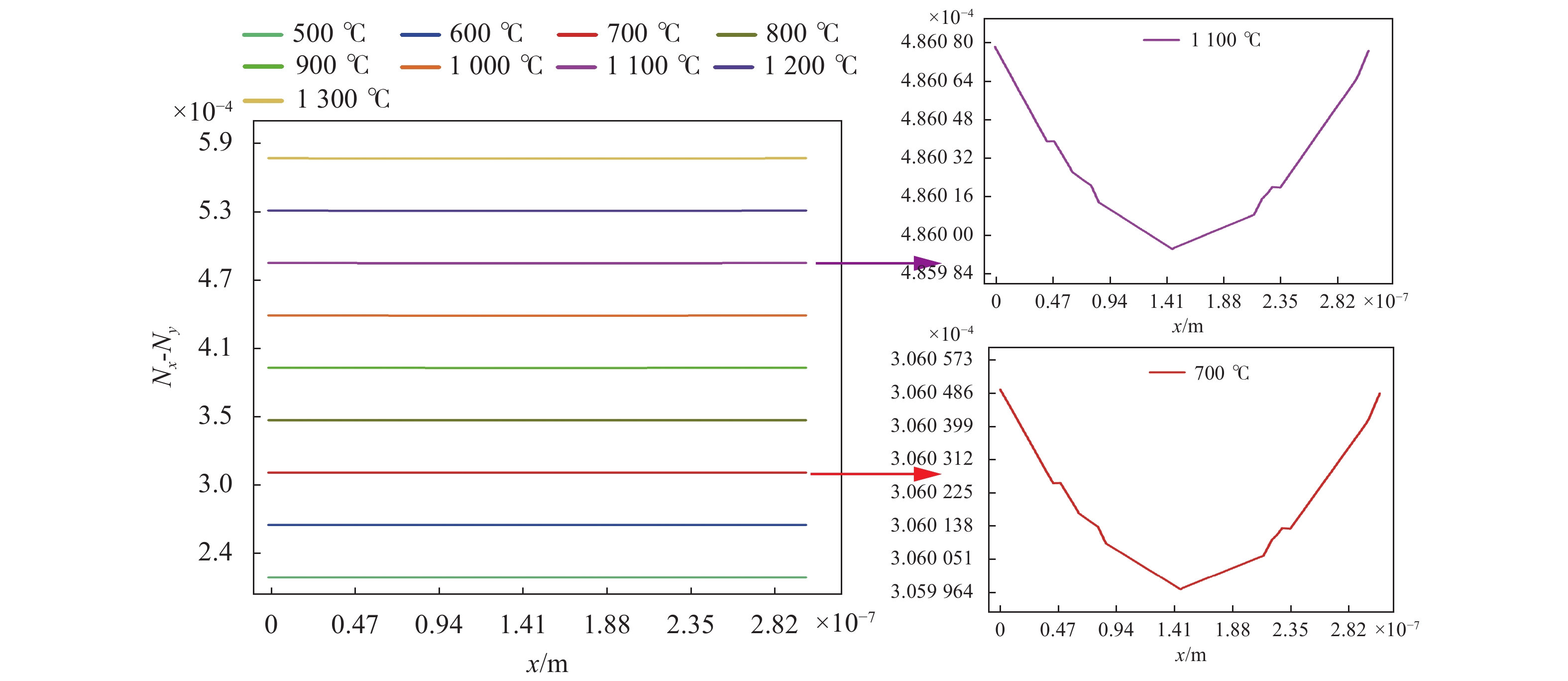
同时,温度的变化还会引起保偏光纤的拍长、偏振串音、偏振消光比发生改变。以0 ℃为界线,分别进行参数调整分析,结果如图9(a)、(b)所示,图中,低于0 ℃时,随着温度降低,双折射值呈上升趋势,温度增幅和双折射增幅呈良好的线性关系;而高于0 ℃时,随着温度上升,双折射值逐步下降。综合来看,保偏光纤在0 ℃以上时受温度影响较大。

Figure 7. Schematic diagram of the relationship between the distance between fiber core and stress zone and birefringence

Figure 8. Schematic diagram of relationship between birefringence and radius of saps

Figure 9. Schematic diagram of relationship between birefringence and temperature. (a) Birefringence diagram of below 0 ℃; (b) Birefringence diagram of above 0 ℃
保偏光纤的生产制造过程参考温度直接影响材料参数,进而改变保偏光纤性能,保偏光纤双折射值与参考温度之间的关系如图10所示。图中,可发现参考温度直接影响保偏光纤双折射数值,参考温度升高,双折射数值增大,通过结合保偏光纤的材料性能和工作温度,可以得到适合系统、满足要求的可靠温度参数。
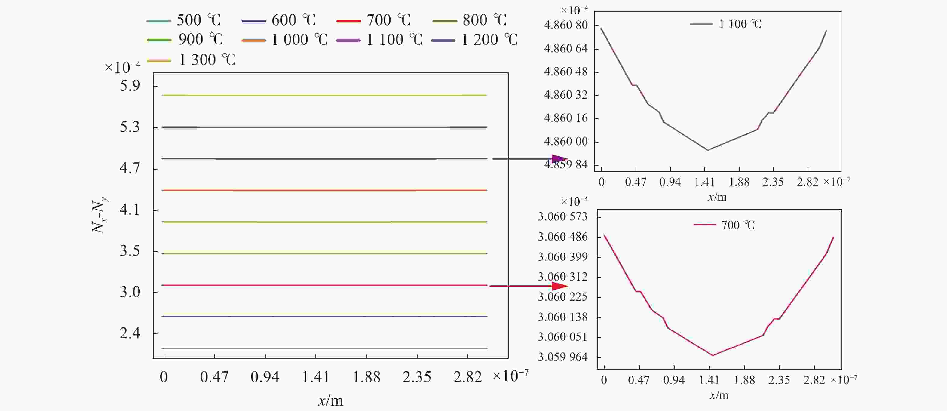
Figure 10. Schematic diagram of relationship between birefringence and reference temperature
芯包比是指保偏光纤纤芯尺寸和包层尺寸比值,是评估保偏光纤的一项重要参数。较低的芯包比能够提高空间分辨率,且保证了传输速率。图11为固定纤芯尺寸后,通过增大包层尺寸降低芯包比的仿真图。由图可知,降低芯包比后,双折射值大幅上升,包层半径增大至
$r2 = 62$ μm以后,增幅变缓,表明控制芯包比的过程中需要同时兼顾包层和纤芯的尺寸,以达到比较理想的比例和效果。
Figure 11. Schematic diagram of relationship between birefringence and the ratio of core to clad
-
采用与2.1节相同的数值模拟条件,分析了领结型保偏光纤的相关性能,应力区小半径为
$a = 9.5$ μm,应力区大半径为$b = 37.5 $ μm,应力区两边扇形角度为 90°。领结型保偏光纤的应力张量如图12所示。图中,应力张量分量${S_x}$ 约为$\left( {0.6 - 0.8} \right) \times {10^8} \;{\rm{N}}/{{\rm{m}}^2}$ ,应力张量分量${S_y}$ 约为$\left( {0.4 - 0.6} \right) \times {10^8} \;{\rm{N}}/{{\rm{m}}^2}$ ,由于应力张量分量${S_x}$ 和${S_y}$ 均为正值且${S_x} > {S_y}$ ,因此纤芯内产生正双折射,根据应力张量数值结果可以得到应力双折射值为${n_B} = c({S_x} - {S_y}) = 7.327\;42 \times {10^{ - 4}}$ 。
Figure 12. Stress component. (a)
${S_x}$ ; (b)${S_y}$ 图13给出了纤芯附近区域的双折射分布。由图可知,与熊猫型保偏光纤类似,在纤芯附近区域,领结型保偏光纤纤芯中心双折射最低,远离纤芯中心,双折射值对称增大。此外,相同条件下领结型保偏光纤双折射值明显大于熊猫型保偏光纤双折射值。

Figure 13. Birefringence curve of bow tie polarization- maintaining fiber core
-
基于有限元分析软件,文中分析了熊猫型保偏光纤、领结型保偏光纤的应力双折射特性,得到以下结论:(1)熊猫型保偏光纤沿x轴存在拉应力,沿y轴存在压应力;(2)对于熊猫型保偏光纤,在纤芯中心附近,双折射值随纤芯与应力区的距离的增大而降低,在高温下工作系统受温度影响较大,双折射值随工作温度升高急速降低,一定范围内,双折射值随参考温度的升高而变大,纤芯尺寸不变时,可以通过增大包层尺寸、增大应力区尺寸提高双折射值;(3)对于领结型保偏光纤,由于其独特的几何结构,具有比熊猫型保偏光纤更优越的双折射值,通过合理调整参数,可以实现许多奇特而优越的光学性能。文中的研究结果可为后期非通视方位传递系统保偏光纤的选择和设计提供更多参考,以期达到更高的传递精度。
Analysis of polarization-maintaining fibers in non-line-of-sight azimuth transmission system
doi: 10.3788/IRLA20210315
- Received Date: 2021-05-17
- Rev Recd Date: 2021-07-05
- Publish Date: 2022-06-08
Fund Project:
National Natural Science Foundation of China (61505254)
-
Key words:
- azimuth transmission /
- polarization-maintaining fiber /
- birefringence /
- stress optical effect /
- finite element analysis
Abstract: According to the design requirements of the birefringence of polarization-maintaining fiber in the non-line-of-sight azimuth transmission system, the influence of different types of polarization-maintaining fiber parameters on the birefringence is emphatically analyzed. Firstly, the stress-optical coupling relationship of polarization-maintaining fiber was deduced based on the stress-strain, variational principle and the stress-photoelastic effect. Then, the influence of different factors on the birefringence of polarization-maintaining fiber was investigated by means of finite element analysis software, and two kinds of polarization-maintaining fiber (Panda polarization-maintaining fiber and Bow-tie polarization-maintaining fiber) were compared and analyzed. The results show that the higher birefringence value near the center of the core can be obtained by a variety of methods, such as reducing the distance between the core and the stress zone, increasing cladding radius when fixing core size, or increasing the reference temperature of the polarization-maintaining fiber. Simultaneously, the birefringence of the bow-tie polarization-maintaining fiber is larger in the same conditions. The research results can provide some reference for the design and selection of polarization-maintaining fiber in the non-line-of-sight azimuth transmission system.


 DownLoad: