


HTML
-
在星地或星间光通信中,二维转台是星载ATP系统指向机构的重要组成部分,广泛应用于空间技术、船舶技术、国防建设等领域。如瑞士OPTEL高性能通信终端[1-2],美国天基空间目标监视系统[3],我国风云三号卫星上搭载的太阳辐射监视仪及嫦娥三号着陆器上搭载的极紫外相机等[4-5]。激光通信常见的指向结构形式有十字跟踪架结构,潜望式结构和摆镜式结构。图1(a)是十字跟踪架式二维转台,具有转动范围大,控制简单等特点,但因其负载为整个光学系统,故转动惯量和结构尺寸非常大。图1(b)是潜望式二维转台,采用两个万向节实现俯仰方位运动,回转半径大,光路经过两次反射,控制光路难度大。图1(c)是摆镜式二维转台,由于负载为反射镜,具有转动惯量小、运动部件质量轻和刚度高等特点,但缺点是俯仰方向调整能力有限,适用于低轨道与高轨道、高轨道对高轨道之间的激光通信。通过对三种转台结构形式的对比研究,根据系统的约束和应用背景,选用摆镜式二维转台结构作为激光通信的光机结构,将其应用在高轨上可避免俯仰方向调整限制的缺点。
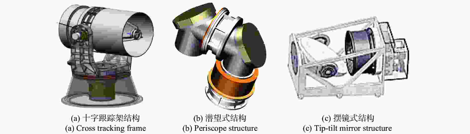
Figure 1. Structure form of two-dimensional turntable
星载二维转台随着卫星发射将经受许多恶劣的环境,在发射过程中二维转台要承受由于运载火箭的加速度而产生的过载以及振动、冲击等严酷的力学环境,需要转台机构具有足够高的刚度抵抗外界环境的干扰。此外,为了降低发射成本,星载二维转台需要轻量化设计,在保证抗力学特性的基础上,降低质量从而节约卫星资源。因此,在充分考虑卫星平台振动特性的基础上,合理设计二维转台整体结构的刚度,既能保证整机满足体积质量的严格限制,又具有抵抗复杂外界环境的抗力学特性。文中的主要工作是对星载二维转台结构设计,包括摆镜组件的高刚度轻量化的集成优化设计,U形架和轴系结构的刚度设计。然后,研究了二维转台进行了有限元建模,特别对影响刚度分析的轴承部件建立了改进的弹簧单元等效模型并推导了等效刚度计算公式。最后对整机结构进行了刚度特性分析和样机试验验证。
-
考虑到二维转台的力学环境及轻量化需求,为了星载二维转台顺利完成光通信的科学目标,表1详细提出了对星载二维转台结构的设计指标。
Parameter Index Clear aperture/mm 183×220 Total weight/kg <12 Resonant frequency/Hz >120 Surface precision ${\rm{{RMS }{_{G{{rav}}} } } } \leqslant \lambda /30$${{\rm{{RMS} }{_{Temp}}} } \leqslant \lambda /40$ Horizontal tracking range/(°) $0-300$ Vertical tracking range/(°) 45±5 Operating temperature/℃ 20±5 Table 1. Design requirements of two-dimensional turntable
-
星载二维转台主要包括方位轴及其驱动组件,俯仰轴系及其驱动组件、U形架与摆镜组件等,星载二维转台总体结构如图2所示。U形架作为连接俯仰轴系和方位轴系的主体,它既是俯仰轴系的支撑结构,又固连于方位轴系;摆镜组件通过转接件与俯仰轴相连接,且由俯仰轴系两端的轴承承载。俯仰轴一端为固定端,轴承选用一对背靠背安装的角接触球轴承(71802AC),采用压圈和端盖压紧轴承内外圈,同时承受径向和轴向两个方向的轴向负载;另一端为固定端,采用深沟球轴承(61802),可以承受径向负载,轴向少量游动可以补偿温度变化造成的影响。方位轴系也是采用一对角接触球轴承(71908AC)来承担双向轴向和径向负载,底端的深沟球轴承(61902)能降低方位轴的径向跳动。
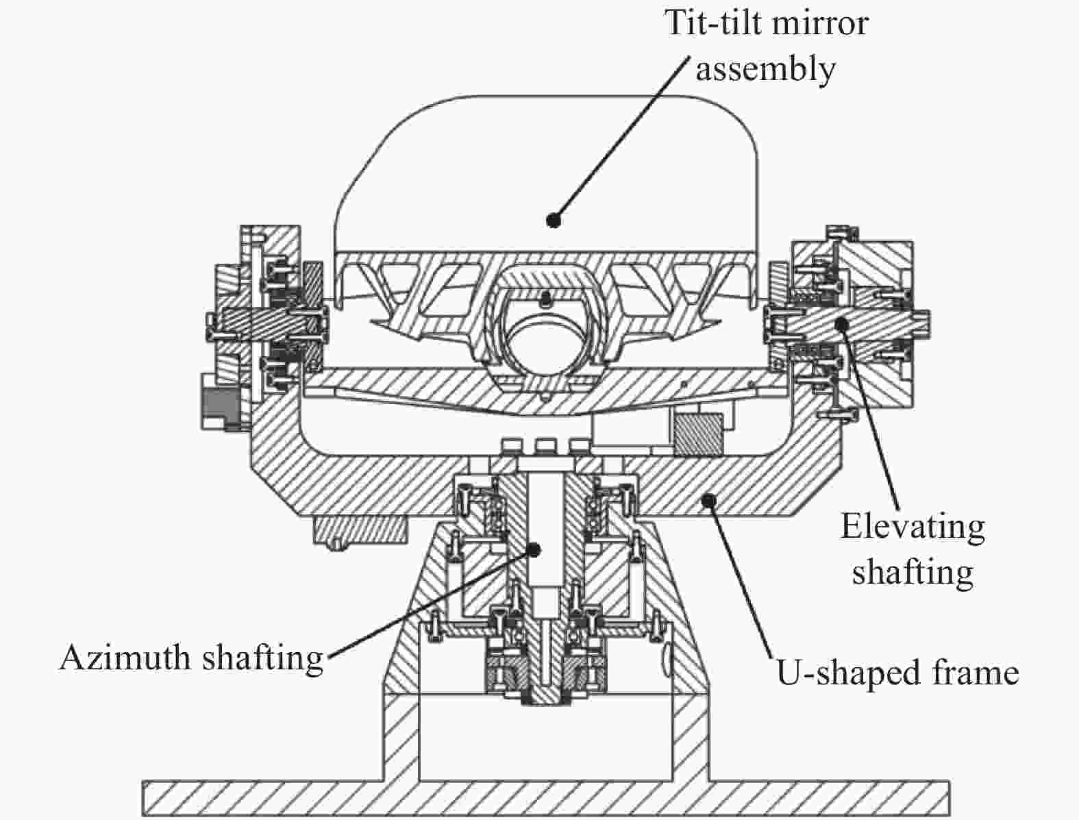
Figure 2. Overall structure of spaceborne two-dimensional turntable
-
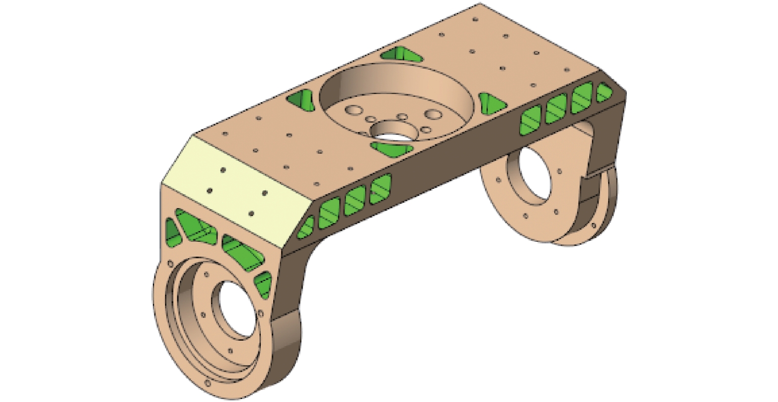
不同于传统椭圆形结构的摆镜,如图3所示,摆镜的外形包络是根据由缩束主镜和粗相机的通光口径在45°平面确定了两个椭圆,并且对摆镜结构进行了上下对称处理,故而摆镜外形包络呈现图3中的结构形式。该摆镜作为系统的粗跟踪机构使用,而系统采用粗精共光轴的设计,摆镜反射镜光束同时一部分进入粗探测,一部分进入精探测,从光路上需要覆盖粗探测和精探测。摆镜材料的选择主要从材料的力学性能和热性能两个方面重点考虑,在众多制造摆镜材料中,碳化硅(SiC)因其比刚度高,光学加工后可以获得较高的光学表面质量,所以SiC作为摆镜的首先材料。在空间摆镜支撑方式中,对于小口径的摆镜,中心支撑结构简单,质量轻,刚度好,并且对摆镜优化设计后可以获得很高的面形精度[6]。轻量化孔形式决定摆镜组件的刚度和重量,因此,针对背部开放式的三角形孔和矩形孔两种结构形式进行优化设计及对比分析。
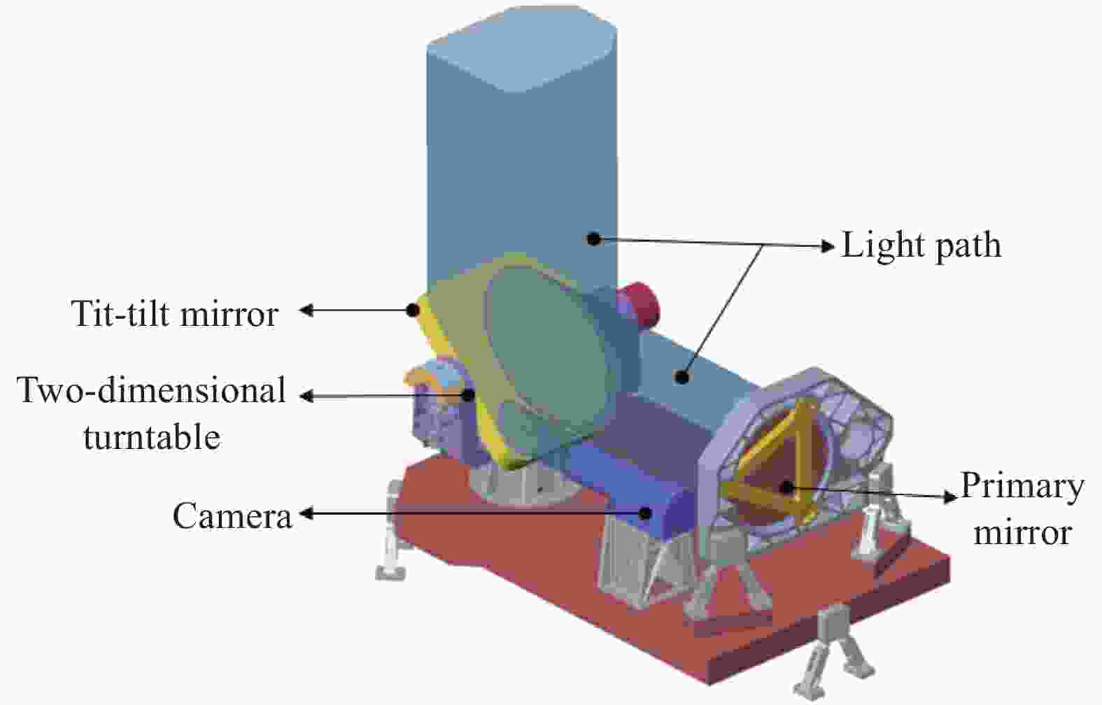
Figure 3. Schematic diagram of part components of the optical machine structure
图4所示为设计的摆镜组件,摆镜与嵌套胶接,柔性支撑螺接嵌套和支撑板,支撑板最终与二维转台俯仰轴系相连,从而实现摆镜的支撑固定,其中嵌套材料为殷刚,柔性支撑材料和支撑板都为钛合金材料(TC4),各结构材料性能见表2。
Material Density/g·cm−3 Young`s modulus/GPa Poisson`s ratio SiC 3.21 446 0.21 Invar 7.98 141 0.3 TC4 4.45 117 0.33 Table 2. Structural material properties of hole tip-tilt mirror assembly

Figure 4. Two kinds of lightweight tip-tilt mirror assembly models
-
为了对两种结构形式的摆镜进行准确的分析比较,利用集成优化方法对其结构参数进行优化设计后,通过对比刚度、质量和面形精度等评价指标对比两种摆镜的结构性能。摆镜优化问题的设计变量包括,镜面厚度(Ft),支撑孔壁厚(Ht),侧壁厚(St),轻量化筋厚(Rti, i=1,2,3,4,5,6)以及轻量化背部形状控制变量(hj, j=1,2,3,4),如图5所示。集成优化中以质量(Mass)和Y向重力工况下面型精度(RMSY)最小为优化目标,以一阶固有频率Freq1,摆镜X向重力工况下面形精度(RMSX)和温升5 ℃的面形精度(RMST5)为约束条件,优化问题描述为:

Figure 5. Schematic of design variables of two back lightweight form tip-tilt mirrors
基于Isight[7]的摆镜集成优化优化结果如表3所示。Result-Ⅰ是矩形轻量化孔的优化结果,Result-Ⅱ是三角形轻量化孔的优化结果。集成优化结果表明,尽管矩形孔式的温升变化下的面形精度RMST5和重量Mass略优于三角形孔式摆镜,但重点关注的结构刚度Freq1和Y向重力工况下的面型精度RMSY却远远不如三角形轻量化形式的优化结果。综上所述,提出的三角形轻量化孔的摆镜结构具有高刚度,高轻量化率和高面形精度。
Variables Domain Result-Ⅰ Result-Ⅱ Ft [2,5] 2.1 2.0 Ht [3,7] 5.5 6.9 St [2,6] 3.2 2.3 Rt1 [2,6] 5.9 5.4 Rt2 [2,6] 2.6 3.8 Rt3 [2,6] 4.0 2.1 Rt4 [2,6] 3.4 2.2 Rt5 [2,6] 3.4 - Rt6 [2,6] 3.2 - h1 [−7,−3] −2.1 −5 h2 [−15,−8] −8.1 - h3 [−20,−10] −18.3 −10.4 h4 [−28,−20] −26.7 −26.4 Freq1 - 355 408 RMSX - 1.793 0.175 RMSY - 10.62 6.603 RMST5 - 0.33 1.2 Mass - 0.95 1.2 Table 3. Design variables and optimal results
-
U形架作为连接俯仰轴系和方位轴系的主体,它的结构刚度和应力变形有着较高的要求。U形架在二维转台整机中质量相对较大,合理的轻量化设计,使其高刚度与低质量两种性能兼备,足以抵御外界复杂的力学环境[8]。首先,二维转台对于质量和体积约束有着很严格的要求,U形架的结构形式为轻量化孔与加强筋相结合,如图6所示,根据对U形架有限元分析,对其轻量化孔区域,加强筋的布置及厚度进行了设计。其次,材料选择方面,由于航天材料选用范围、可靠性和整机质量的限制,在载荷的阻尼设计上受到很多限制[9]。故选用了铸造铝基复合材料(LY12)作为二维转台主支撑结构(U形架、光学主体框架、轴系基座)的加工基材。这种材料具有很高的比模量,而且材料阻尼系数也较一般镁合金(AZ41M)和钛合金(TC4)高。表4对比了这三种不同U形架材料的质量和模态。
Material Mass/kg Modal 1st 2nd 3rd LY12 1.598 446 696 806 AZ41M 1.010 430 675 795 TC4 2.628 439 689 798 Table 4. Analysis results of three different U-shaped frame materials

Figure 6. U-shaped frame lightweight structure
由表4可以看出,镁合金(AZ41M)材料相比于其他两种材料质量最轻,为1.010 kg,但是对应的前三阶模态也是最低,一阶模态为430 Hz;铝合金(LY12)材料刚度最高,一阶模态为446 Hz,并且重量在许可范围内,为1.598 kg;钛合金(TC4)材料不仅质量大,而且固有频率也相比较低。如图7所示,更近一步,对铝合金材料U形架应力分析,在沿着发射方向Y向重力加速度过载9 g作用下,最大应力在U形架底部,为13.3 MPa。铝合金材料的屈服极限为420 MPa,结构应力远小于其屈服极限,U形架结构强度满足设计需求。

Figure 7. Stress response nephogram of the U-shape structure
-
俯仰轴系和方位轴系的刚度决定了整个转台的谐振频率,要求二维转台机构能抵抗发射,振动和在轨运行等复杂的空间环境的影响[10]。如图8所示,轴系配置分固定端和游动端两部分,俯仰方位轴系均采用“一端背对背角接触球轴承,一端为深沟球轴承”的配置方式。固定端靠近负载面安装,支撑轴承采用一对背对背角接触球轴承同时实现轴向与径向支撑,通过选择不同的轴承型号和接触角来调整和分配轴向、径向的支撑刚度。游动端用于轴向温升卸载和降低尾部轴系跳动,对轴向支撑不起作用,故游动端轴承常采用深沟球轴承。

Figure 8. Shafting structure design section
俯仰/方位-角接触轴承公称内径
$\phi 17\;{\rm{mm}}$ 和$\phi 35\;{\rm{mm}}$ ,采用背对背安装方式,轴与轴承外圈、轴承与轴套、轴套与U形架立柱间均采用过盈配合,过盈量在0.001~0.003 mm范围内;俯仰/方位-深沟球轴承公称内径$\phi 15\;{\rm{mm}}$ ,轴与轴承间、轴承与轴套间采用过盈配合,深沟球轴承外圈通过轴用压圈固定,内圈不做定位。俯仰/方位轴承固定端采用接触角为$25^\circ $ 的P4精度角接触球轴承,俯仰/方位轴承游动端采用P5精度的深沟球轴承。轴承装配时需要锁紧,通过调整隔圈的厚度来控制轴向预紧量。轴承各部件装配完成时,要求不存在轴向跳动,满足俯仰轴的轴系晃动量小于$ 5''$ ,方位轴的轴系晃动量小于$ 10''$ 。根据如上的设计轴系结构具有很高的轴向和径向刚度,能够满足力学环境试验的技术指标要求。 -
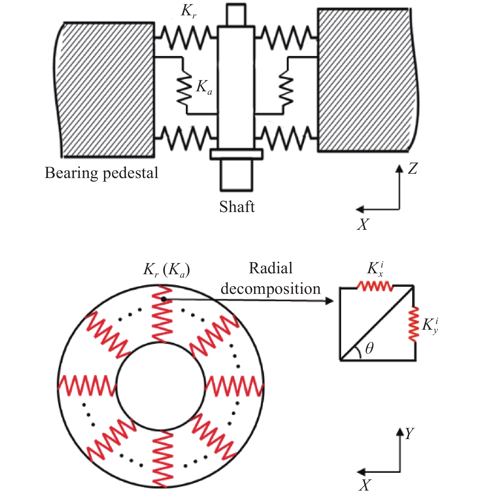
轴系结构是二维转台中的重要部件,它的刚度特性直接影响整个转台的力学性能。由于轴承的结构较为复杂,包含了滚动体与内外滚道的结合部、轴承外圈与轴承座的结合部及轴承内圈与主轴结合部。如果对每一部分精细建模,建立模型就很复杂并且不可避免的建模误差,所以对轴承准确的力学等效建模是非常必要的[11]。为了刚度分析的方便,往往将轴承的结构视为一个整体,这样就只需要考虑轴承表现出的综合力学参数。根据转轴的受力和运动方式,可以将轴承等效为上下左右均匀布置的四组弹簧阻尼单元[12-14]。尽管这种等效方式涉及参数和自由度较少,但为了能更精细的反应轴承内部的力学模型,采取将轴承中每一个滚珠等效为一组弹簧单元,将所有弹簧单元均匀布置于轴径的圆周方向上,如图9所示。

Figure 9. Schematic diagram of the bearing equivalent model
基于Hertz点接触理论[15],对于轴承中的单个的滚动体,定义单个滚动体与两个滚道之间的法向趋近量
$\delta $ ,轴承接触角为α,滚珠与内圈滚道接触的曲率和函数$\displaystyle\sum {\rho _i^{1/3}} $ 和滚珠与外圈滚道接触的曲率和函数$\displaystyle\sum {\rho _{{e}}^{1/3}}$ ,则可推导出仅受单一径向或轴向载荷时,刚度系数$K$ 、径向刚度${K_r}$ 和轴向刚度${K_a}$ :如图9所示每组弹簧单元处分别设置一个轴向弹簧和径向弹簧,设
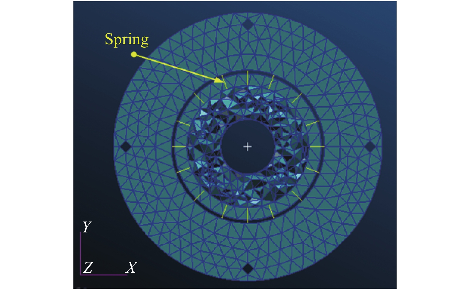
$K_{{x}}^i$ 、$K_{{y}}^i$ 、$K_z^i$ 分别代表第i个弹簧单元的X、Y、Z三个方向的等效刚度,滚轴数目为n。在圆周方向上任意位置取一组弹簧单元,设其与X方向夹角为${\theta _i}$ (i=1···n),则满足如下关系式:以方位轴-角接触球轴承为例阐述建模方法,其他轴承的等效建模不再赘述。图10所示为方位轴系中的角接触球轴承简化后的局部有限元模型,轴径上布置了16组弹簧单元,根据有限元网格划分情况,在轴径圆周方向均匀布置。由表5得到的计算结果和公式(5)~(6)对简化模型中处于任意位置的弹簧单元刚度进行求解,由于弹簧单元数目较多,其具体计算结果数据不予以列出。在Hypermesh中用Cbush单元模拟的弹簧,并在Property的Pbush单元属性中赋予计算的刚度值,忽略阻尼、摩擦等非线性因素。结合已划分好网格的其他部件,建立了二维转台轴承的等效有限元建模。
Name Stiffness/N·mm−1 Ka Kr 71802 $4.579\;9 \times {10^4}$ $3.084\;4 \times {10^5}$ 61802 - $2.570\;7 \times {10^5}$ 71908 $2.367\;3 \times {10^5}$ $7.509\;3 \times {10^5}$ 61902 - $3.104\;3 \times {10^5}$ Table 5. Angular contact bearing and deep groove ball bearing stiffness calculation results

Figure 10. Simplified local finite element model of angular contact ball bearing
-
对二维转台模型经过简化处理,将不必要的倒圆角,孔及曲面特征删除。方位轴系及俯仰轴系使用4.1节中轴承的等效建模方法应用在二维转台的整机有限元建模中,有限元建模选用实体单元Hex6作为网格单元,共有网格单元420556,有限元模型如图11所示。二维转台在X、Y、Z方向的固有频率及振型如表6所示。
Table 6. Modal analysis results of two-dimensional turntable

Figure 11. Finite element model of two-dimensional turntable
二维转台仿真分析计算得到三个方向的模态,分别为X向115.5 Hz、Y向235.8 Hz、Z向369.8 Hz。模态分析结果见表6。三个方向X、Y、Z一阶频率振型见图12。

Figure 12. Mode diagram of two-dimensional turntable
-
图13是样机力学试验现场,为了验证二维转台的结构设计合理性和刚度分析的正确性,采用了与二维转台设计模型结构1∶1的试验样机进行了三个方向的0.2 g的特征试验,正弦振动和随机振动试验,表7给出了特征扫频试验的结果及仿真误差。
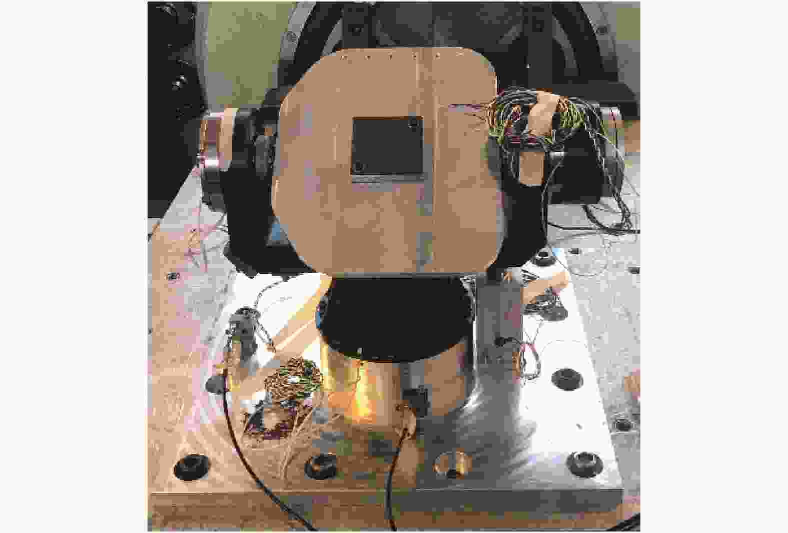
Figure 13. Mechanics test of two-dimensional turntable
二维转台模拟样机力学试验结果与有限元分析结果一致性良好,相对误差在6%以内,满足有限元分析误差范围内。表明有限元仿真分析结果比较准确,改进的弹簧单元模拟的轴承能有效应用在二维转台的工程分析之中。图14是沿X向特征扫频响应曲线。
Orientation Experiment FEA Relative error X 111.9 115.5 3.6% Y 222.74 235.8 5.9% Z 351.3 369.8 5.3% Table 7. Mechanics test results and simulation errors of two-dimensional turntable
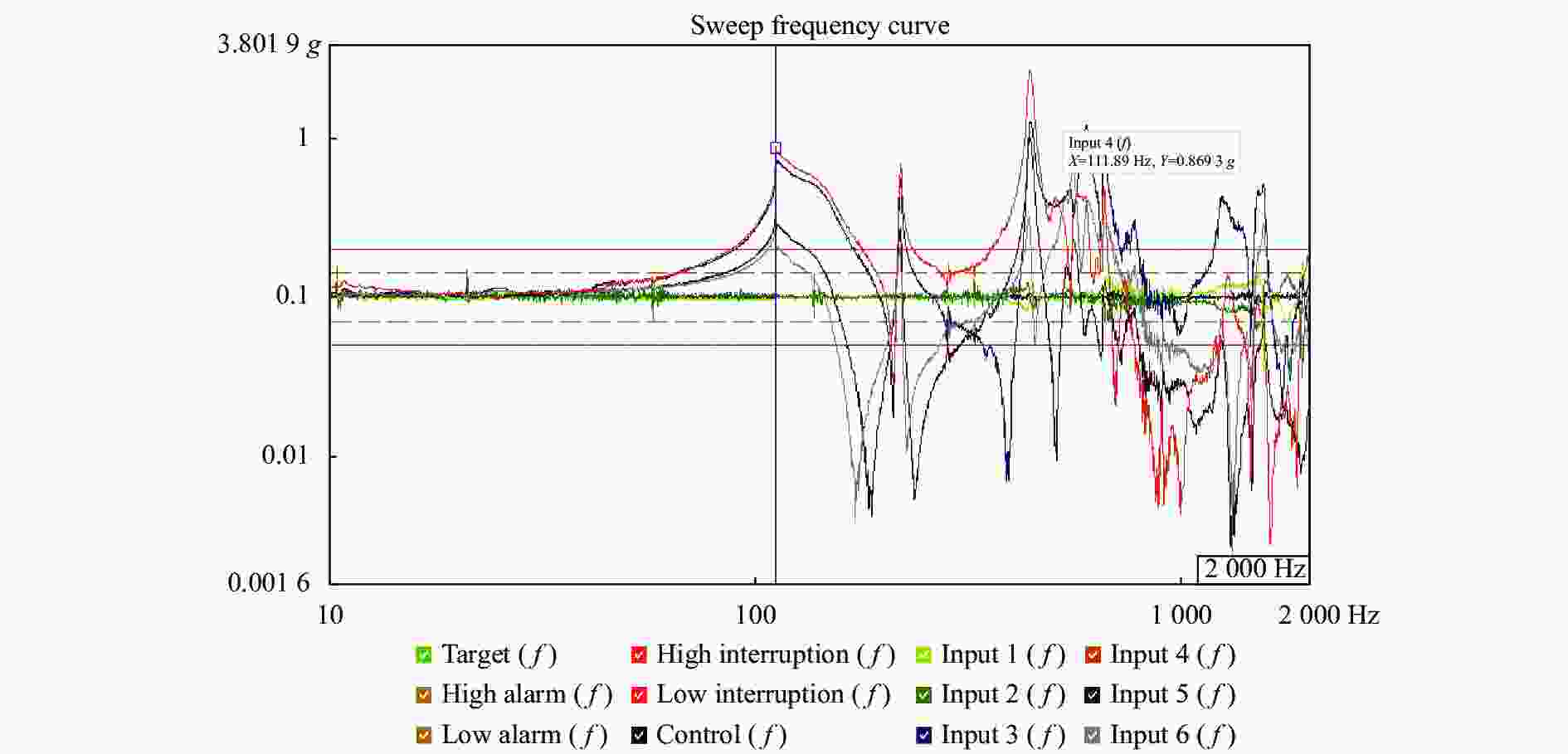
Figure 14. Sweep frequency curve of the direction of X
-
根据星载小型二维转台的结构需求,主要从整机的刚度及轻量化等方面对二维转台结构进行了详细设计和刚度分析,包括对摆镜组件的轻量化设计、U形架的刚度设计,轴系结构的刚度设计和等效建模及整机结构的刚度分析。二维转台的有限元分析及力学试验验证表明,转台的俯仰轴系、方位轴系刚度设计良好,高轻量化高刚度的摆镜组件和U形架满足具有较高的刚度和强度。二维转台在X、Y、Z三个方向刚度分析的固有频率与力学试验验证结果误差在6%以内,说明轴承的等效建模方式能够准确的模拟轴承的刚度特性,适用于二维转台的刚度分析。通过对星载二维转台的动力学试验表明,在保证了二维转台的质量约束和刚度需求,各部分组成部件结构刚度设计合理。


 DownLoad: