


-
太阳光为世间万物提供能量,光波的反射、折射与散射为我们勾勒出五彩斑斓的世界。相机帮我们记录下美好的瞬间、利用光的反射可以对样品的含量进行分析、望远镜让我们瞭望星海、显微镜帮助我们认识微观世界,这些光信息皆是光给我们带来的福利。
但是,光在散射介质里传播的过程中会经历散射现象,使传播的光强信息受到干扰。偏振作为光的基本属性,也可以作为信息的一个维度[1],由于其与物质相互作用所表现出来的一系列优势而广泛应用于生物医学[2-3]、光通信[4]、大气遥感[5]、三维成像[6]、图像复原和质量提升[7-10]等诸多领域。从20世纪起,国内外课题组进行了一系列利用红外偏振技术对海面目标探测、地面目标探测的研究[11-13],在海面场景中,水体的红外辐射呈现出较强的偏振特性;而在地物场景中,自然物体的红外偏振度较小,人造物体则呈现出较强的偏振特性,利用偏振特征的不同,可以实现对目标和背景进行分辨。
光在生物组织中传播时会经历多次散射,散射光的偏振态与散射介质的微观结构密切相关,通过对散射光偏振态变化的解析可获得散射体的结构信息。因此,偏振信息可用于对浅层生物组织高分辨率和高灵敏度探测,是一种行之有效的早期(某些特定)癌症诊断方法[14]。目前光的偏振角(Angle of Polarization, AoP)、偏振度(Degree of Polarization, DoP)信息已经被用于癌症的诊断,Anderson 等[15]也将“偏振差”方法应用于皮肤癌的检测。Jacques等[16]利用DoP对癌变组织进行检测,实验结果表明,DoP相比于偏振差更具有区分皮肤癌变和正常组织边界的能力。然而生物组织内部结构复杂,为此人们尝试寻找更多与特定微观结构对应的偏振参量。MM(Mueller Matrix)作为散射介质的“名片”,包含丰富的组织微观结构信息,可以用于癌变组织检测[17]。然而,MM元素物理意义不够清晰,MM所蕴含的信息难以直接解构提取。为了解决这一问题,MM被分解为双向衰减矩阵(
${{{M}}_{{D}}}$ )、延迟矩阵(${{{M}}_{{R}}}$ )和退偏矩阵(${{{M}}_{{\Delta }}}$ )[18],并通过MM得到退偏指数${P_\Delta }$ ,上述参数可应用于生物医学检测等诸多领域,实现对不同退偏组织进行分辨[19-21]。传统的偏振指标对散射介质的变化不敏感,不能对散射介质的细微差别进行分辨[22-23]。近年来,一种新的偏振表征方法—偏振纯度指数(Index of Polarization Purities, IPPs)被提出[24-26],用于表征散射介质及目标的退偏特性,相对于传统的DoP、AoP、Stokes矢量等表征方式,IPPs表征方式可以提供散射介质及目标更多新的维度信息。文中综述了IPPs的理论,以及其在目标识别、医学检测、不同分散体系的退偏特性分析等方面的应用研究进展,并且展望了IPPs表征方案的具体应用方式及前景。
-
光与散射介质相互作用时,光的偏振状态会改变,可以用Stokes矢量及MM来描述这种现象。Stokes矢量的四个分量的物理意义与偏振椭圆的椭圆度ε和方位角θ有关[27]。偏振光在散射介质中传输过程中发生的偏振状态的改变可以使用4×4的MM来描述[28],以这样一种方式,出射光的Stokes矢量可表示为入射光Stokes矢量和MM的乘积。散射介质的MM可以通过测量辐射得到,这些辐射是由不同偏振状态的偏振光对散射介质及目标进行照明产生的,并随后对辐射的偏振进行分析,这种情况用下列表达式在数学上加以描述:
式中:I为由辐射强度组成的n×n矩阵;MSample为样品的4×4 MM;SPSG是一个4×n矩阵,其中n列表示照亮样品的不同偏振态的Stokes矢量;SPSA是一个n×4矩阵,它是n行Stokes向量的转置,这些向量代表从偏振分析仪出射的偏振态。通过计算分析仪和照明矩阵(SPSA和SPSG)的伪逆,可以推导出MM,得到:
上式表明至少需要四组不同照明和分析状态用于测量完整的MM。因此,至少需要16次辐射测量才能完全确定散射介质及目标的MM。
无源线性光学系统(退偏系统)可以等效为四个纯系统(非退偏系统)的非相干叠加[29-32]。穆勒-琼斯矩阵(Muller-Jones Matrix, MJM)可用来描述一个纯系统,所有的完全偏振光入射到这个纯系统后,不会发生退偏,出射光的DoP仍然等于1。并且所有纯系统MJM都满足无源性的条件,即透光率永远不超过1[29]:
式中:
${{{g}}_{{f}}}$ 表示纯系统的正向无源条件;${{{g}}_{{r}}}$ 表示纯系统的反向无源条件。任意退偏系统等效为四个纯系统的非相干叠加,因此可以得到,任何退偏系统MM必须满足正向无源条件:同时还要满足反向无源条件:
从退偏系统MM中提取出来的协方差为半正定矩阵H(M),能够体现出退偏系统的统计信息。协方差矩阵H(M)与其对应的退偏系统MM之间的关系可以表示为[29]:
由于MM与其协方差矩阵H(M)之间的一对一关系,所以任何以MM表示的并行分解都可以直接转换成以H(M)表示的对应表达式[29]。MM可分解为四个纯系统MJM,其相对权重由H(M)的特征值大小决定。
H(M)的特征值可以写成如下形式:
现在考虑H(M)的四个特征值之间的相对差异,即纯系统相对权重之间的差异。从H(M)的特征值中可以定义三个新的无量纲的不变量。这三个量包含了有关偏振纯度的所有信息,被称为IPPs:
式中:trH表示H(M)的迹,在退偏系统等效分解成的四个纯系统中;
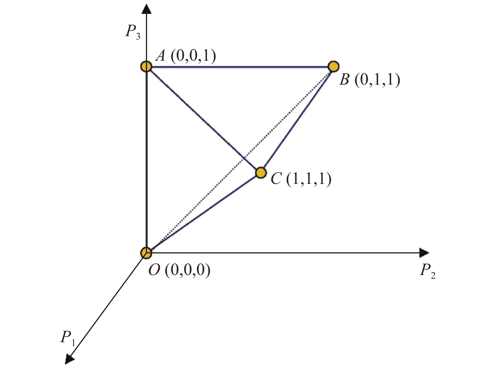
${P_1}$ 表示权重最大的两个纯系统的权重之差;${P_2}$ 表示权重最大的两个纯系统权重之和减去权重第三的纯系统的权重的两倍;${P_3}$ 表示权重最大三个纯系统的权重之和减去权重最小的纯系统权重的三倍[32]。IPPs构成纯度空间的可行域如图1所示[32],其是由${P_1}$ 、${P_2}$ 、${P_3}$ 构成的三维数学空间,它们不是完全独立的,而是相互关联的。纯度空间不仅提供了光在相互作用中被退偏的信息,而且还提供了关于它是如何被样品退偏的信息[29]。利用${P_1}$ 、${P_2}$ 、${P_3}$ 的不同,可以揭示不同退偏系统之间的差异,从而用于区分不同类型的退偏系统。图中O点代表完全退偏的系统,IPPs都等于0;C点IPPs都等于1,代表纯系统。系统的退偏能力越弱,分布在纯度空间中的表征点越靠近C点;相反,系统退偏能力越强,表征点就越靠近O点。与IPPs提供完整的退偏信息相比,退偏指数${P_\Delta }$ 提供了样品整体退偏能力,其可从IPPs中计算得到: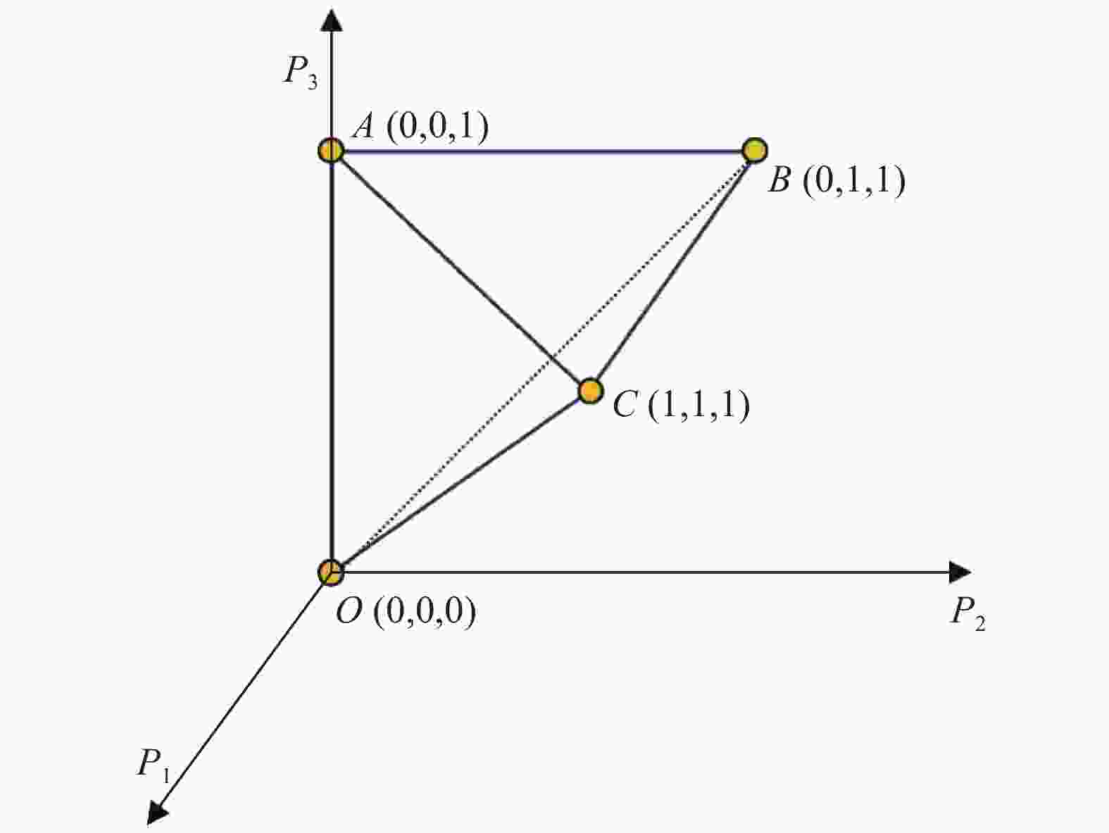
Figure 1. IPPs’ feasible region
也可从MM中计算得到:
-
偏振光在散射介质中传播时,会因为和散射介质发生相互作用而退偏,从而改变其偏振状态。于是可以通过出射光的偏振状态来间接表征散射介质的退偏特性[33-37]。但是利用出射光的偏振态对散射介质的退偏特性进行表征时,会因为入射光的偏振状态不同而改变,从而不能很好的表征散射介质的退偏特性。近年来,笔者课题组使用IPPs对散射介质的退偏特性进行研究[33-34]。研究表明对于单粒子均匀散射体系而言,散射粒子的数密度、入射光波的波长以及相对折射率对散射介质的退偏特性有较大影响;当散射介质是由多种分散微粒组成时,散射介质的退偏特性与粒子的混合比有关。当散射介质为单分散均匀体系,在后向探测时[33],散射介质的退偏能力随散射粒子的数密度的增加而增强。入射光波的波长相同时,随着散射介质相对折射率的增大,散射介质的退偏能力先减弱后增强。在前向探测时[34],随着传输距离增加,散射介质的退偏能力增强,随着入射波长增加,散射介质的退偏能力减弱。
当散射介质为双分散体系时,张曼[33]等人利用纯度空间对散射介质的退偏特性进行分析,如图2所示。根据纯度空间中每个点的特殊意义,在O点上,IPPs都等于0,代表完全退偏的散射介质;在C点上,IPPs都等于1,代表完全非退偏的散射介质。散射介质的退偏能力越弱,分布在纯度空间中的表征点越靠近C点,相反,散射介质退偏能力越强,在纯度空间中的表征点越靠近O点。如图2(a)所示,当发射可见光并在后向接收时,随着双粒子混合体系中瑞利小颗粒体积比例的增加,散射介质对应在纯度空间中的表征点逐渐趋近于C点,这说明介质的退偏能力随着小粒子体积比例的增加而减弱。这是由于随着散射介质中小粒子的体积比的逐渐增加,会使得光子与小粒子碰撞的几率增加,后向探测器会接收到更多散射角较大的光子,而这些散射角较大的光子偏振状态变化较小,导致散射介质退偏能力的减弱。当发射红外辐射并在前向探测时[34],情况如图2(b)所示,随着小粒子的增加,散射介质的保偏性逐渐增强。上述结果表明,双粒子混合散射介质中退偏能力取决于小粒子在整个散射介质中的混合体积比,即散射介质中瑞利散射微粒的增加将导致散射介质退偏能力的减弱。

Figure 2. (a)
${P_1}$ ,${P_2}$ ,${P_3}$ varying with the proportion of small particles in the purity space (backward detection); (b)${P_\Delta }$ of scattering medium as a function of the proportion of small particles (forward detection); (c)${P_1}$ ,${P_2}$ ,${P_3}$ varying with different mean values for standard deviation of 0.01 μm (backward detection); (d)${P_1}$ ,${P_2}$ ,${P_3}$ varying with different mean values for standard deviation of 1.05 μm (backward detection)当散射介质为多分散体系时,假设散射介质中的粒子大小满足对数正态分布,在此基础上研究了两种不同标准差下,均值逐渐增大时散射介质的退偏能力。同样的,将后向探测散射介质的IPPs在纯度空间上表示出来。在标准差分别为0.01 μm、1.05 μm的情况下,粒子分布的均值变化范围为0.1~2.1 μm时,可见光后向探测到散射介质退偏能力如图2(c)~(d)所示。纯度空间里分布的点随着粒子均值的增加越来越接近O点,也就是说粒子的平均值变大,散射介质的退偏能力增强,这说明多分散体系中粒子分布的标准差的差异不会改变散射介质退偏能力的总体变化趋势。
清华大学马辉教授课题组针对散射介质提出了一种新的物理可实现空间[38],其横坐标为
${P_\Delta }$ ,纵坐标为$PI{\rm{ = }}\sqrt {{\rm{((}}{P_{\rm{1}}}{{\rm{)}}^{\rm{2}}}{\rm{ + (}}{P_{\rm{2}}}{{\rm{)}}^{\rm{2}}}{\rm{ + (}}{P_{\rm{3}}}{{\rm{)}}^{\rm{2}}})/3} $ ,提出的物理可实现的空间相比于S(M)-${P_\Delta }$ 空间[39]有了很大的改进,提供了一个更加简单的几何表示,更便于对散射介质进行分类。同样的,他们利用蒙特卡洛(MC)算法得到了单分散体系下,对于不同的散射系数(5 cm−1,10 cm−1, 15 cm−1),随着粒子半径的增加,前向和后向散射在PI-${P_\Delta }$ 空间中的分布。结果表明,在前向散射的过程中,PI随着粒子直径的增大而增大;在后向散射过程中,随着散射介质中粒子直径的变化,PI的值随着${P_\Delta }$ 的变化关系在空间中呈现出一条曲线。 -
植物组织图像的对比度可以通过二色性或双折射的测量加以提高。二色性与植物结构对光的偏振依赖性吸收有关,其在很多研究中都被成功地用于揭示植物中叶绿体和相关细胞器的组织和浓度[40-41]。双折射也已成功地用于表征双折射大分子。但退偏作为一种偏振特性,通常被忽略。当不同偏振态的光子非相干地到达探测器的同一区域时,就会出现退偏现象。在植物中,退偏主要是由位于组织内的细胞、细胞器和其他元素散射光引起的。迄今为止,最常用的探测植物组织退偏的方法是测量散射光的DoP。由于DoP依赖于植物成分的内在特征,它是对给定标本状态的一种有针对性和信息性的观察。然而,一种更普遍的方法,IPPs在植物学却上很少被使用。
近来,Albert Van Eeckhout开始尝试利用IPPs对植物组织进行成像,标本为植物叶片。实验中对叶片的退偏进行测量,得到对叶片偏振响应进行编码的MM图像。为了从测量的MM图像中获得进一步的物理信息,对MM图像进行分解,得到一组后续的偏振和退偏振度量图像。在实验中,Albert Van Eeckhout课题组使用了退偏指数
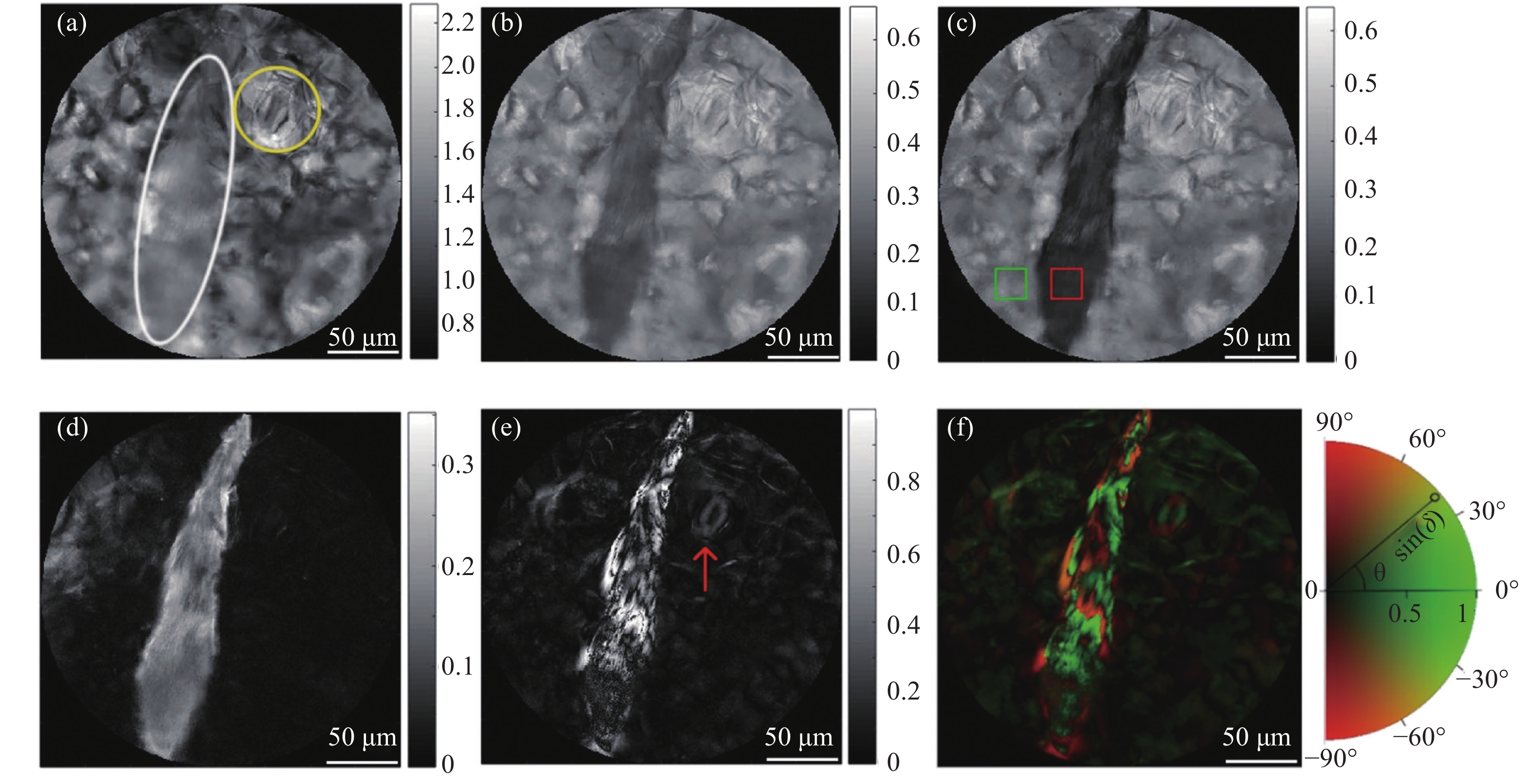
${P_\Delta }$ 和IPPs观测数据,${P_\Delta }$ 和IPPs能够根据其对照明光退偏能力的不同对微观结构进行分类。其中,${P_\Delta }$ 表示散射介质总体的退偏能力,而IPPs可以区分散射介质中不同的退偏成分。图3(b)~(d)为${P_\Delta }$ ,${P_1}$ ,以及${P_2}$ -${P_1}$ 对应的图像。图3(e)显示了植物线性延迟的图像,图3(f)显示其伪彩色图像,它给出了叶片成像区域结构的双折射信息。在图3(b)~(e)中可以看到菊粉的细长形状,菊粉是一种针状结晶的多糖,针状晶体倾向于聚集在一起形成裂片,这种裂片存在于一些植物的实质细胞中。在图3(b)~(e)中,针状晶体的边缘可以清晰的区分出来,整个结构与背景形成了高度对比。在${P_1}$ 图像(图3(c))中,针状晶体红色方形区域的${P_1}$ 平均值为0.11,而与背景相对应的绿色方形区域的${P_1}$ 平均值为0.29,${P_1}$ 的值分别在0.11和0.29附近很好地聚为两组,这表明了${P_1}$ 能够区分不同类型的物质,而这在非偏振光图像下(图3(a))是不可能的。图3(d)中${P_2}$ -${P_1}$ 的观察结果显示,针状晶体的同一部分的值约为0.13,而背景单元格的同一部分的值为0.02。对于不同的退偏物体,${P_1}$ 和${P_2}$ -${P_1}$ 针状晶体的能见度比${P_\Delta }$ 高。因此,使用IPPs观察退偏物体比使用${P_\Delta }$ 和传统的光强效果更好。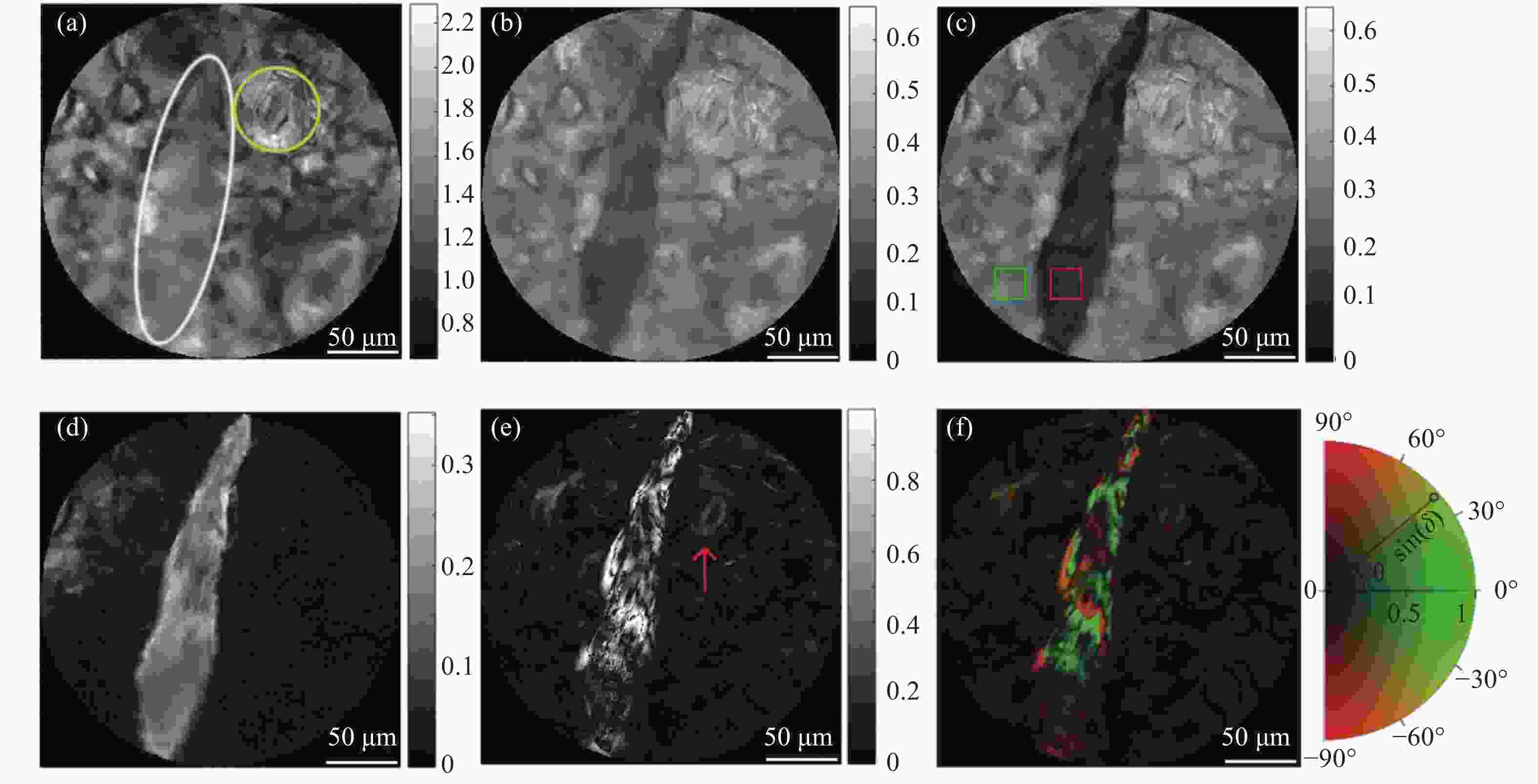
Figure 3. Polarization analysis of leaf. (a) Intensity; (b)
${P_\Delta }$ ; (c)${P_1}$ ; (d)${P_2}$ –${P_1}$ ; (e) Linear retardance δ and (f) Pseudo-colored image of linear retardanceAlbert Van Eeckhout团队同样利用IPPs对动物组织进行观测。实验选取了兔腿上的肌肉作为实验样品,使用MM成像时对比度太差,以至于无法对不同生物结构进行分辨,接着他们利用IPPs对生物组织进行成像。IPPs在成像的过程中则具有较好的分辨能力,会导致某些生物结构的对比度增大。并且IPPs与传统方法相比,不需要进行偏振分解,其中的
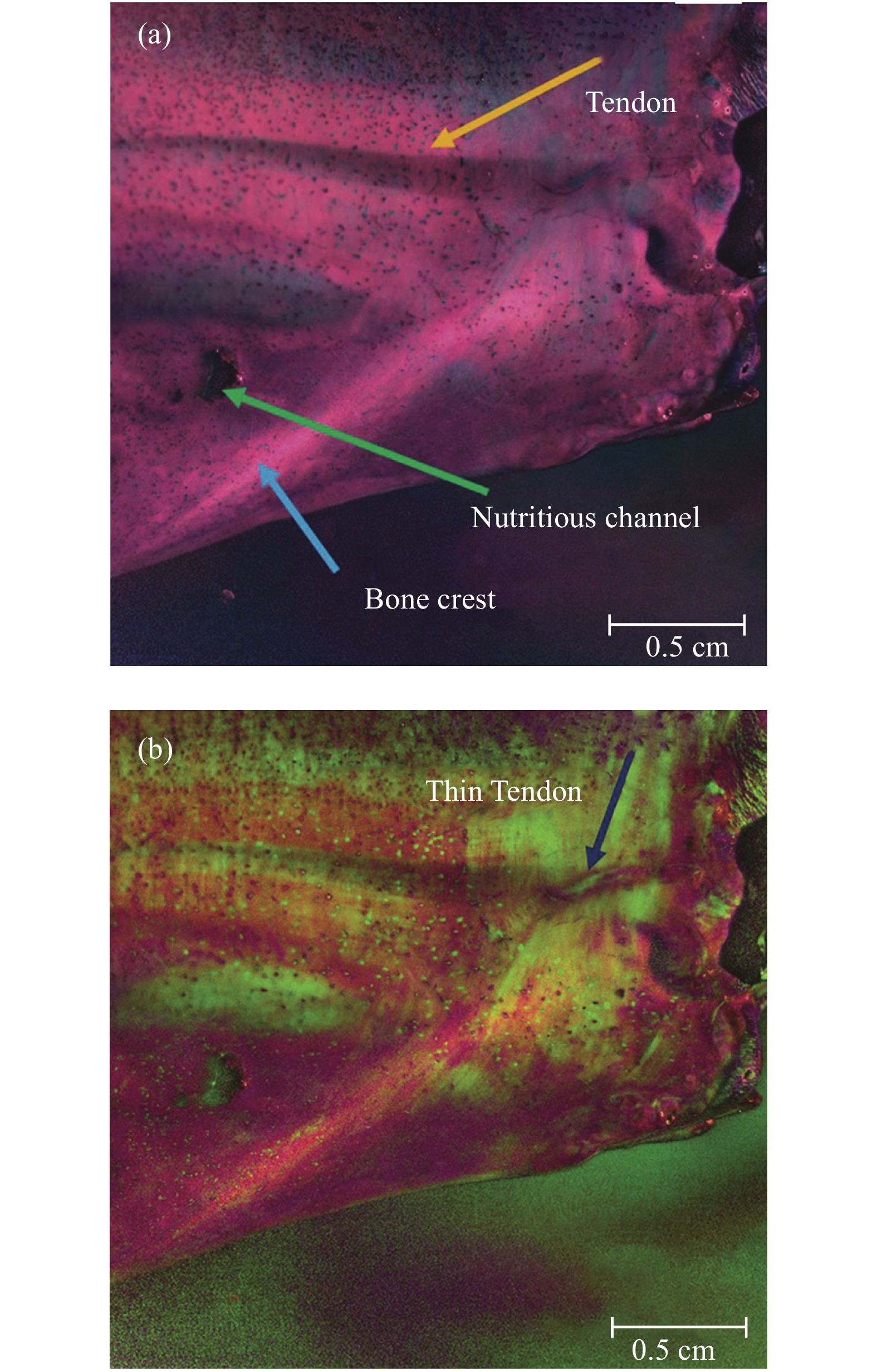
${P_1}$ 、${P_2}$ 、${P_3}$ 易于获得。紧接着为了进一步的增加不同结构之间的对比度,Albert Van Eeckhout团队利用伪彩色的方法对实验样品的成像结果进行进一步处理,结果如图4所示。通过伪彩色来编码由IPPs提供的偏振信息的方法不是唯一的,其主要目的是尽可能使生物样本目标结构对比度更大,所以需要给
${P_1}$ 、${P_2}$ 、${P_3}$ 设置不同的权重,即α1、α2和α3的取值不同会使得具有不同偏振属性的结构成像的清晰度不同。图4中给出了两种不同的组合,首先,为了得到图4(a)中的图像,使用公式(11)对成像图片进行伪彩色处理,选取α1=3、α2=1和α3=1,这种组合增加了${P_1}$ 通道的权重,从而放大了骨孔和营养通道的对比度。视觉效果如图4(a)所示,其中营养通道形成了很高的对比度(见图4(a)绿色箭头)。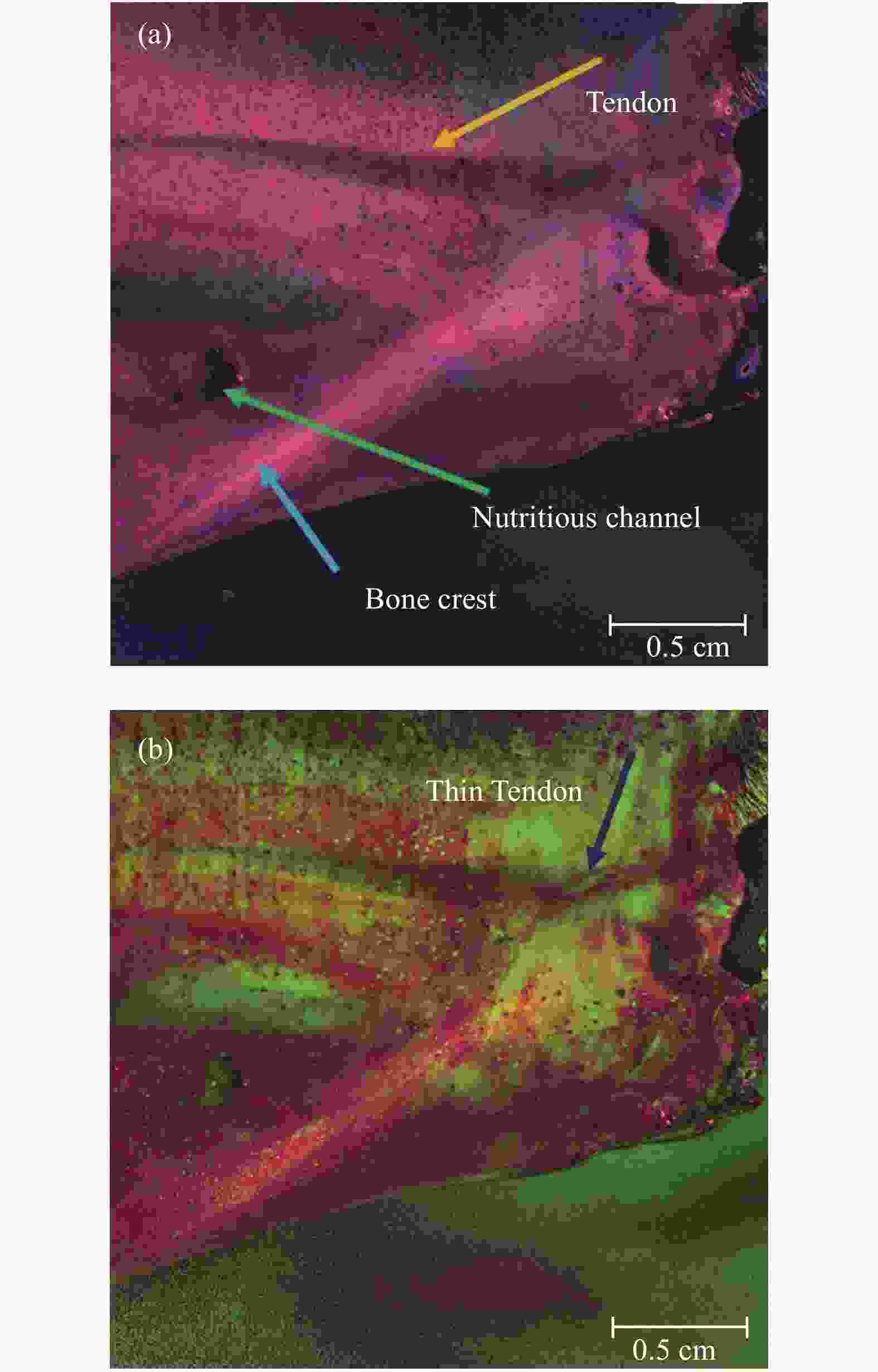
Figure 4. Pseudo-colored image of different bases and weights. (a) α1 = 3, α2 = 1 and α3 = 1 of Eq. (11); (b) α1 = 2, α2 = 2 and α3 = 1 of Eq. (12)
此时,修改公式(11)中的权重,甚至进一步修改伪彩色编码关系本身,以增加目标结构区域的对比度,即可以调整伪颜色编码的基,突出目标结构区域。例如,修改了公式(11)中的基,变成了公式(12):
公式(12)使用了一组非正交的伪色基。公式(12)中α1、α2和α3范围也是0~1,不过与公式(11)中考虑伪彩色空间中的点不同,公式(12)选择的非正交轴更接近于一个四面体,四面体中点的色差更大。设置权重α1 = 2、α2 = 2和α3 = 1可最大化斑点状结构和薄肌腱的对比度,得到图4(b)中的图像,薄肌腱现在可以更好地显示(见图4(b)蓝色箭头),斑点状结构清晰可见。实验表明,IPPs在对生物组织进行成像的过程中确实具有独特的优势,并且通过选取伪彩色的基和权重可以对生物组织的目标结构进行突出显示。
-
目前,糖尿病已成为第三大严重危害人类健康的疾病,也是全世界非常关注的问题之一。同时,糖尿病导致的并发症有很多,会危害人的心、脑、肾、血管、神经、皮肤等。糖尿病患者在治疗时血糖的增高或降低,也可能直接导致患者死亡。因此,糖尿病患者需要一种无创血糖监测仪来提高监测频率,更好地指导治疗。尽管其中一些技术已经达到了相当高的精度,到目前为止,没有一种技术被批准用于临床。偏振光为监测葡萄糖浓度(Glucose Concentration,GC)提供了一种可行的方法,其通过GC引起的偏振变化进行浓度的监测。Chou[42]和Pu[43]使用高灵敏度的偏光技术识别与生理GC相关的偏振面的旋转。Ablitt[44]等人利用MC模拟研究了含有手性球状粒子的混浊介质对偏振光散射的影响。Wang[45]开发了一种MC方法,利用单散射模型或双散射模型提取含葡萄糖双折射混浊溶液的MM元素。Phan和Lo[46]使用由偏振扫描发生器和高精度Stokes偏振仪组成的Stokes-MM偏振测量系统,分别检测有散射效应和无散射效应水溶液中的低浓度葡萄糖样品,但由于信噪比较小,检测葡萄糖引起的偏振面小角度的旋转是相当困难的。
近年来,笔者课题组提出利用IPPs对GC进行监测[47],并利用MC算法搭建了实验平台。结果表明,IPPs中的
${P_1}$ 相比较于传统的偏振指标对GC变化更加敏感更具有优势,可以用于指示和监测溶液中的GC。在前向散射探测中,粒径越大,优势越明显,结果如图5所示。接着拟合出${P_1}$ 与GC的多项式关系,通过拟合出的多项式对GC进行反演,误差低于5%。
Figure 5. P1 and DoP varying with GC (forward scatter)
然而,在后向散射探测中,IPPs不能明显的反映出溶液中GC的变化。但是在前向散射的过程中,
${P_1}$ 体现了对GC监测的能力,于是该课题组利用${P_1}$ 频率分布直方图来显示GC的变化。首先,将${P_1}$ 值的区间划分为30等份,分别计算每个区间上的值,然后,将直方图与曲线进行拟合,如图6(e)~(h)所示,其中N为归一化频率。如图6(a)~(b)所示,发现有葡萄糖和没有葡萄糖的两种溶液的${P_1}$ 分布有显著的不同,但在不同GC的溶液中,如图6(b)~(d),${P_1}$ 的空间分布没有明显的区别。从${P_1}$ 的频率分布直方图6(e)~(h)可以看出,随着溶液中GC的增加,最大值点的位置逐渐向左移动,这与正向散射结论一致。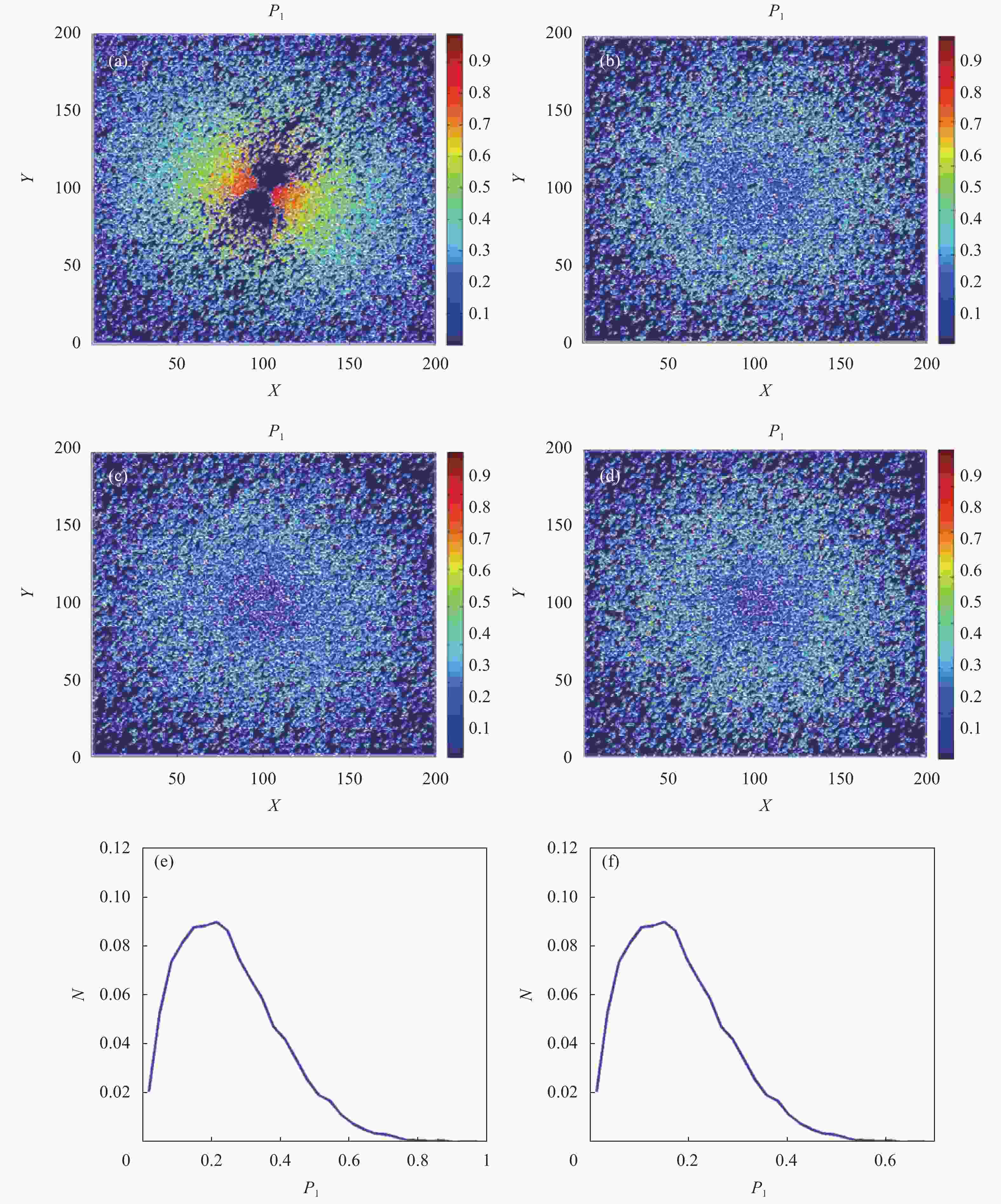
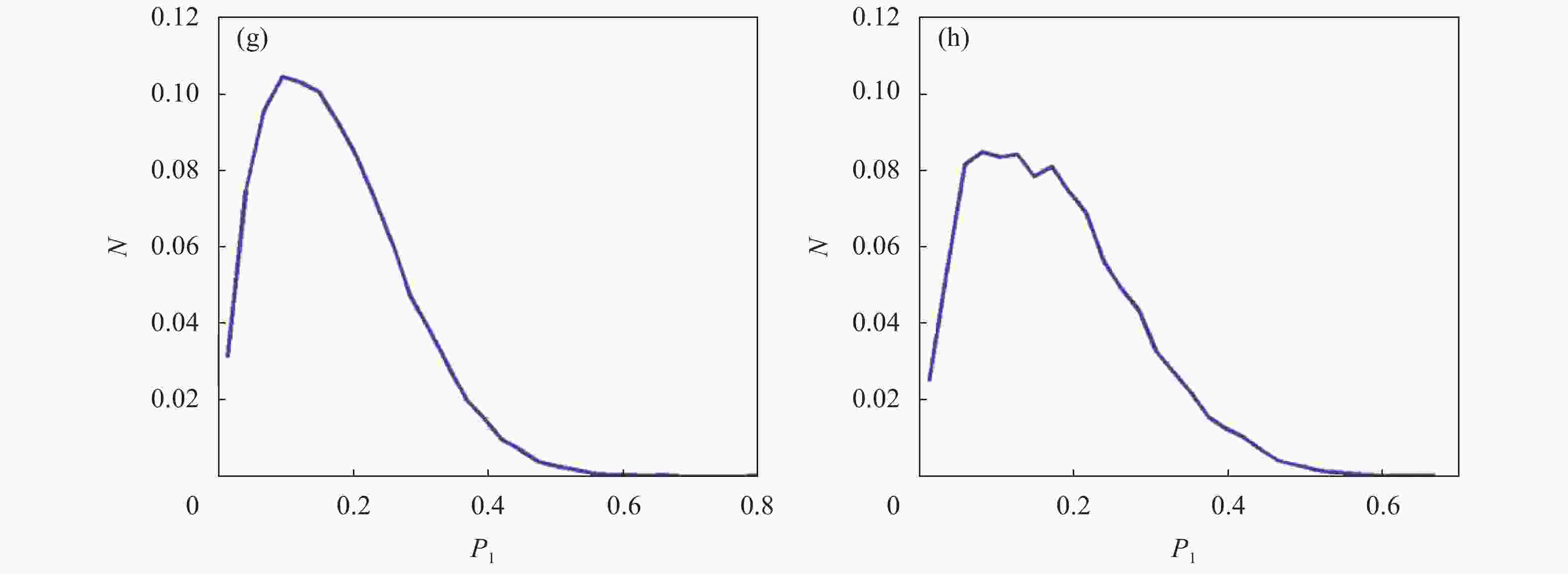
Figure 6. Space distribation and frequency distribution histogram of
${P_1}$ of detecting board with four kinds of GCs -
表征反射光的偏振变化过程对探测偏振分布、揭示目标特征具有重要意义,可用于偏振遥感[48-49]、目标检测与识别[50-52]。当目标表面不光滑时,反射光会具有不同的传播方向,即发生了散射。粗糙表面的反射通常使用双向反射分布函数(Bidirectional Reflection Distribution Function, BRDF)建模[53-55]。Wang[56]等人将MC算法与BRDF模型相结合,提出了一种从粗糙表面获取反射偏振信息的方法。然而,这些模型因为没有考虑目标的退偏特性,所以识别的精度比较低,也无法对隐藏下的目标进行识别。而目标的退偏特性可以用IPPs来表征。合肥工业大学郭忠义课题组基于BRDF模型、利用MC算法搭建实验环境并利用IPPs对伪装下的目标进行识别[57]。
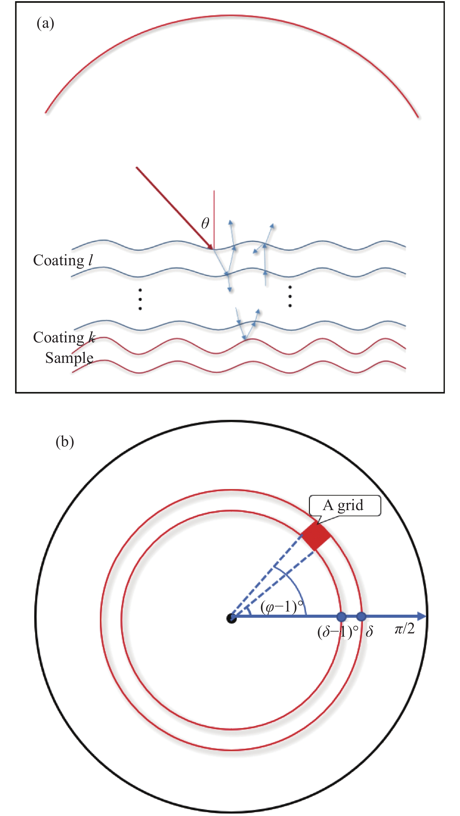
实验中使用632.8 nm的激光以天顶角θ照射到涂层,当光照射到涂层时,会发生折射和反射。反射光将立刻被上半球接收,折射光则会通过一系列的反射和折射,最终被上半球接收,模型图如图7(a)所示。接收前,将上半球分成90×360个网格,俯视图如图7(b)所示。根据相应网格中的方位角和天顶角收集出射光,即对到达同一个网格中的光叠加求Stokes矢量。因为不同网格中收集的反射光经历了不同的散射过程,所以携带了关于目标的多维信息。

Figure 7. (a) Model of refraction and reflection; (b) Top view of upper hemisphere
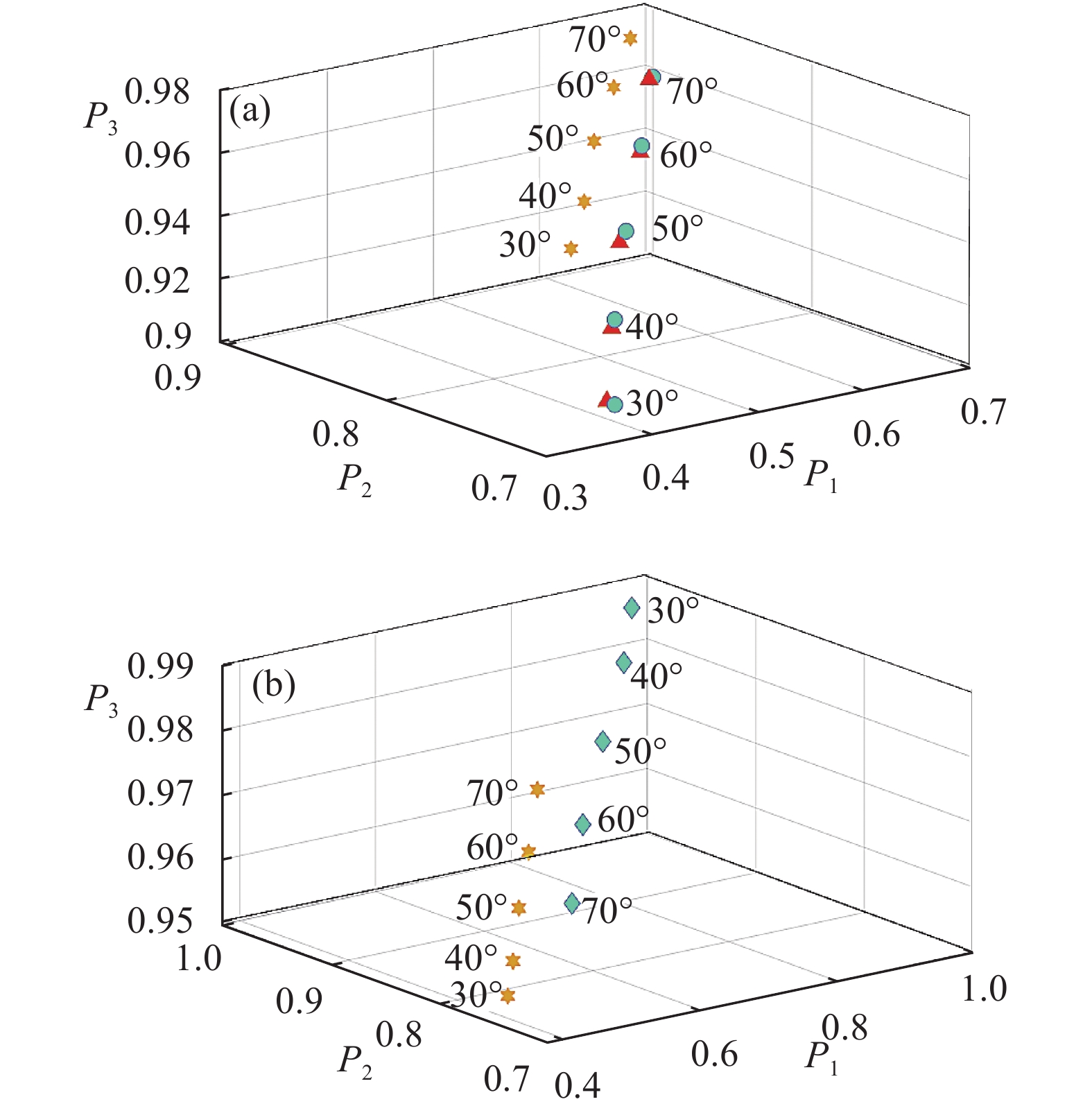
为了研究目标的退偏特性与入射角的关系,将有机涂层的表面粗糙度固定为0.2,入射角分别设置为30°、40°、50°、60°和70°计算得到上半球
${P_1}$ 、${P_2}$ 、${P_3}$ 的平均值在IPPs空间上的分布,如图8所示。
Figure 8. Distributions of
${P_1}$ ,${P_2}$ ,${P_3}$ corresponding to different incident angles. (a) Samples as Cu, Au, Al; (b) Samples as Al, Al2O3在
${P_1}$ 、${P_2}$ 、${P_3}$ 构成的IPPs空间中,点(1,1,1)代表完全非退偏目标,其他点代表退偏目标,可以根据IPPs空间中的坐标来表示目标固有的退偏特性。图8说明随着入射角的增加,金属的退偏能力逐渐减弱而氧化物的退偏能力逐渐增强,这说明金属和氧化物对入射角的依赖性相反。此外,Cu在IPPs空间分布结果接近于Au,而远离Al和Al2O3,这一现象取决于目标的折射率。由于Cu的折射率与Au的折射率相似,但与Al和Al2O3的折射率有很大的不同,所以不同的材质的目标在IPPs空间中的分布不同,这使得伪装目标的探测、识别成为可能。同时,整个上半球的${P_1}$ 、${P_2}$ 、${P_3}$ 分布随入射角的变化情况如图9所示。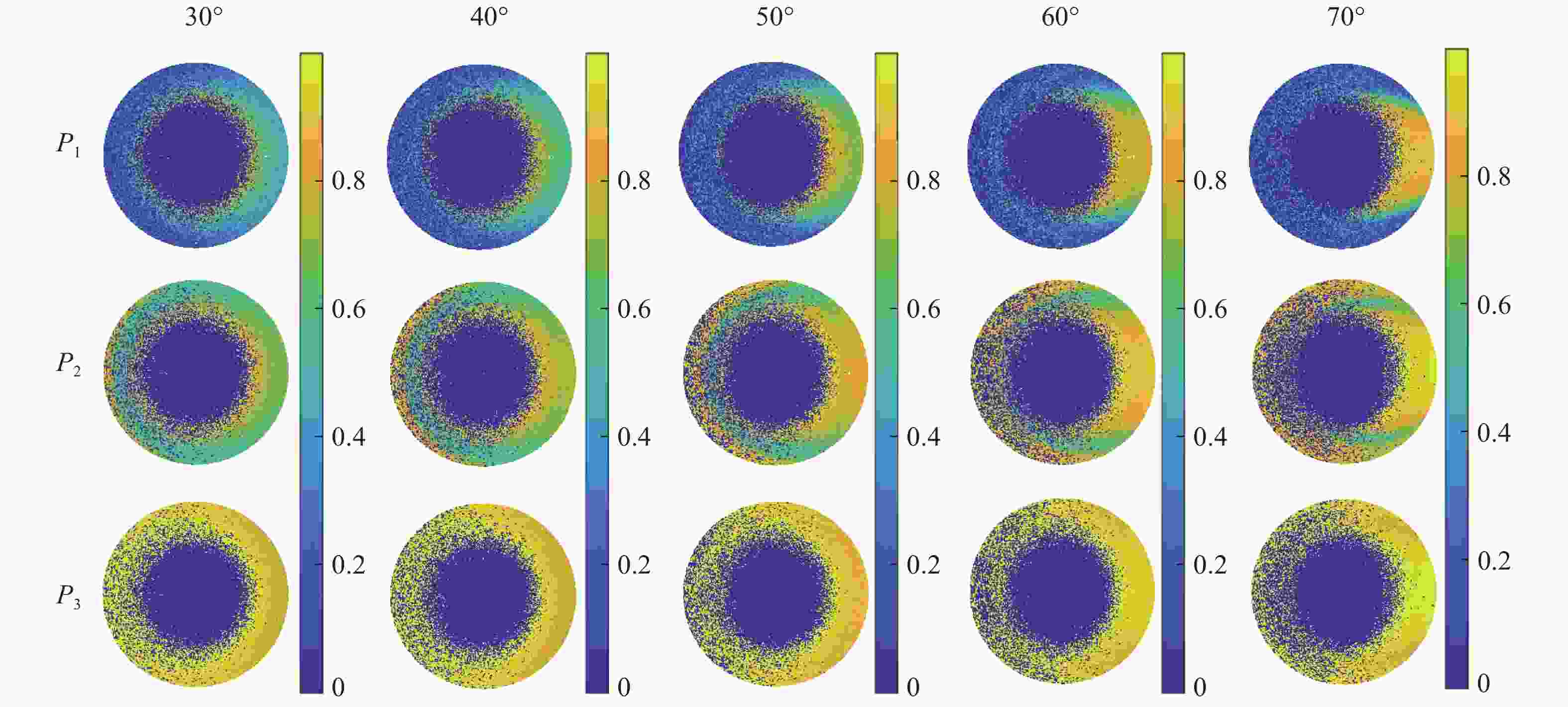
Figure 9.
${P_1}$ ,${P_2}$ ,${P_3}$ of each grid in the upper hemisphere varying with the incident angles (Cu)上半球网格中存在物理不可实现点[29]。以Cu为例,当
${P_1}$ 、${P_2}$ 、${P_3}$ 的值为零时,说明由协方差矩阵H(M)导出的特征值为负,称为物理不可实现点,即其不在图1的可行域中。可以看出,物理不可实现点的数量随着入射角的增大而减少,入射角变大,物理可实现点有向圆心扩散的趋势。此外,不同网格的${P_1}$ 、${P_2}$ 、${P_3}$ 也不相同,意味着不同网格所表现的目标的退偏特性也是不同的。该课题组同样研究了IPPs随目标表面粗糙度的变化情况,结果表明随着粗糙度的增大,
${P_1}$ 、${P_2}$ 、${P_3}$ 的值逐渐减小,说明无论是金属还是氧化物,其退偏能力都随着粗糙度的增大而增强。这是因为在粗糙的表面上,光会发生多次散射,导致入射光的退偏效应增强。此外,利用IPPs对伪装下的目标进行识别的过程中,因为目标对上半球不同网格接收到的光的编码不同,造成不同网格所展现出的目标的退偏特性不同。所以也可以结合不同网格的IPPs信息,实现伪装下的目标识别[57]。 -
文中从IPPs的来源出发,综述了IPPs较传统偏振指标的优越性以及其在生物医学、目标识别等方面的重要应用。IPPs从MM中来,但是比MM具有更简便的形式,较传统的偏振指标具有更多维的信息。在用于生物医学成像的过程中,因为组织中不同结构之间的退偏特性不同,从而可以对不同的结构进行分辨。并且,由于IPPs可以表征介质及目标更多维的信息,从而可以利用IPPs监测介质及目标的微小变化。正因如此,IPPs可以用来对目标进行识别,即使目标被伪装,也可利用IPPs的变化对目标进行成像、识别。但目前利用IPPs对退偏结构进行成像时,IPPs与特定退偏结构的对应编码关系,尚需要进一步深化研究。在今后的发展中,IPPs可以用于在传统偏振指标所不能解决的问题领域发挥积极作用,可以进一步的探索其在生物医学领域的应用,探索不同退偏结构和IPPs之间对应的编码关系,也可以将IPPs信息与人工智能相结合,通过对IPPs偏振特性数据的相关特征学习,也许可以为下一代更加智能化、更高信息维度化的目标检测、识别提供强有力的技术方案。
Research progress on theory and applications of index of polarization purities
doi: 10.3788/IRLA20210373
- Received Date: 2021-12-10
- Rev Recd Date: 2022-01-25
- Publish Date: 2022-04-07
Fund Project:
National Natural Science Foundation of China (61775050,61971177);Fundamental Research Funds for the Central Universities(PA2019GDZC0098)
-
Key words:
- polarization information /
- index of polarization purities (IPPs) /
- imaging /
- target recognition
Abstract: The optical information will experience the scattering phenomena, when it propagates in the scattering media, which will change the intensity and polarization information of the propagating light. And the depolarization property and the transmission property of the medium can be characterized indirectly, which can be used to classify and recognize the media. In theory, the Mueller Matrix (MM) can describe all polarization properties of the media, which plays a vital role in analyzing the depolarization properties of the medium, but its parameters are too complicated. However, the index of polarization purities (IPPs) obtained from the Mueller matrix can also describe the polarization properties of the media directly. IPPs are composed of


 DownLoad: