


-
大幅宽成像可以缩短卫星的重访周期,提高观测的时间分辨率;高分辨遥感图像可以提供更精细的几何特征信息,提高目标识别能力[1];多角度遥感通过地面目标多个方向的观察,使得对目标的观测信息更加丰富,为定量遥感提供了多元的信息,有利于提高遥感数据定量化水平[2];大幅宽、高分辨率、多角度三者结合,将会是未来对地遥感的重要发展方向。
目前超大幅宽对地成像方式主要有多载荷视场拼接、高轨成像和光机扫描成像。其中,光机扫描成像方式具有机动、灵活、容易实现且成本低的特点,在机载、航天大幅宽成像观测中得到广泛应用[3],如:美国MODIS[4]、我国风云三号中分辨率成像光谱仪采用反射镜摆扫的光机扫描方案[5],美国VIIRS、我国海洋一号C/D星上定标光谱仪以及正在研制的新一代海洋水温水色仪采用主光学望远扫描的光机扫描方案[6-9]。但超大幅宽成像时,传统光机扫描成像方式受观测斜距、地球曲率的影响,使得地面空间分辨率随扫描角度增大而迅速降低,降低视场边缘目标可探性的;同时带来观测天顶角逐渐增大,成像幅宽范围内大气斜程路径差异大,影响定量化应用的问题。
文中提出了一种基于斜视等距扫描的成像方法,旨在解决大幅宽光机扫描成像过程中视场边缘地面空间分辨率急剧降低、不同像元大气程辐射差异大而影响定量化应用的问题。推导了大幅宽斜视等距扫描成像过程中扫描方向与垂直扫描方向(线阵方向)空间分辨率随扫描角度的关系式,幅宽随扫描角度的关系式;进一步给出了该成像体制,通过卫星平台俯仰机动实现多角度观测时分辨率、幅宽的数学表达式,并进行了仿真分析。为大幅宽成像提供了一种新的解决途径,对推动超大幅宽、高分辨率、多角度遥感的发展具有一定参考意义。
-
由于受观测斜距、地球曲率的双重影响,穿轨光机扫描成像方式空间分辨率随扫描角度增大而迅速降低,导致地面轨迹存在明显的蝴蝶结效应[10-11]。以卫星运行轨道高度705 km、相机焦距4250 mm、探测器像元尺寸10 μm、扫描角度范围
$ \left[ { - {{60}^ \circ },{{60}^ \circ }} \right] $ 为例,图1给出了中心视场像元沿轨$ GS{D_x} $ 及穿轨$ GS{D_y} $ 两个方向分辨率的退化情况,可以看出沿轨与穿轨方向地面分辨率从星下点1.66 m分别退化到扫描边缘4.25、15.44 m,分辨率退化严重。图2给出了1976年美国标准大气、乡村可视距离5 km气象条件下,该相机从星下点到视场边缘成像,可见到长波红外全谱段的大气程辐射在相机入瞳总能量的占比随观测天顶角的变化趋势,星下点观测天顶角为0°时大气程辐射占比为42.2%,扫描边缘观测天顶角为60°,大气程辐射增加到56.32%,大气程辐射差异大。为此,文中提出了一种斜视等距扫描成像方案用以解决上述问题。
Figure 1. GSD of cross-track scanning imaging

Figure 2. Proportion of atmospheric radiation in the total energy of imager entrance pupil
-
如图3所示,建立坐标系,X方向为卫星平台飞行方向,Z方向指向地心,Y方向满足右手坐标系扫描镜与XOY平面夹角为
$ \theta $ ,扫描镜旋转轴为P,卫星不姿态机动时,P轴与Z方向平行。光学系统光轴方向与Y轴平行,探测器位置固定,线阵方向平行于X轴,垂直线阵方向平行于Y轴。扫描成像过程中,探测器任一像元$ i $ 扫描的物方矢量为圆锥形,对应的探测斜距相同,地面投影扫描轨迹为环带,中心视场像元对应的观测天顶角为$ 2\theta $ 。因此,可以消除传统穿轨光机扫描成像时探测斜距对分辨率的影响。此外,采用斜视等距观测时大气路径相同,大幅宽成像时不同视场的大气程辐射接近,利于降低大气程辐射的影响及载荷的定量化应用。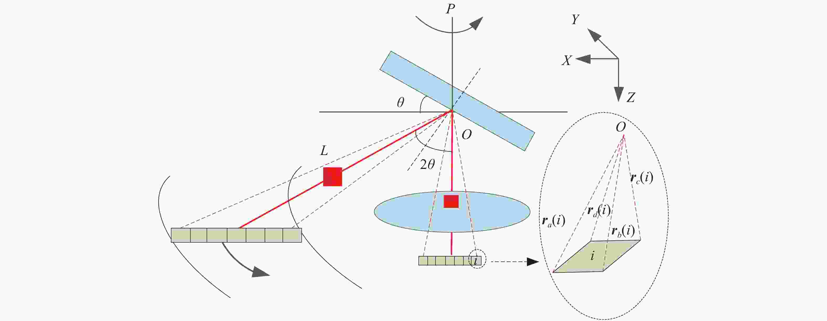
Figure 3. Schematic diagram of imaging principle
-
如图1所示,任一像元
$ i $ 的像方矢量用矩形四个角点的单位化矢量表示:${{\boldsymbol{r}}_I} = \left[ {{{\boldsymbol{r}}_a}\left( i \right),{{\boldsymbol{r}}_b}\left( i \right),{{\boldsymbol{r}}_c}\left( i \right),{{\boldsymbol{r}}_d}\left( i \right)} \right]$ 。根据光学反射矢量基本理论,对应的单位化物方矢量${{\boldsymbol{r}}_E}\left( {i,\;\beta } \right) = \left[ {{{\boldsymbol{r}}_{a'}}\left( {i,\;\beta } \right),{{\boldsymbol{r}}_{b'}}\left( {i,\;\beta } \right),{{\boldsymbol{r}}_{c'}}\left( {i,\;\beta } \right),{{\boldsymbol{r}}_{d'}}\left( {i,\;\beta } \right)} \right]$ 可以由像方矢量$ {{\boldsymbol{r}}_I} $ 及法线向量${{\boldsymbol{N}}_{\boldsymbol{\;\beta }}} = {[{N_{\;\beta ,x}},{N_{\;\beta ,y}},{N_{\;\beta ,z}}]^{\rm{T}}}$ 决定的反射矩阵$ {R_N}\left( \;\beta \right) $ 线性表示[12]:当扫描角度
$ \;\;\beta = {0^ \circ } $ 时,扫描镜法线与X轴、Z轴、探测器线阵在同一平面内,初始法线矢量为${{\boldsymbol{N}}_{0}} = {\left[ {\sin \theta ,0,\cos\theta } \right]^{\rm{T}}}$ 。当扫描镜绕P轴转动时,法线矢量为[13]:式中:
${\boldsymbol{S}_{P,\;\;\beta }}$ 为转动矩阵。矢量
${\boldsymbol{P}}{\text{ = }}{\left[ {{P_x},{P_y},{P_{\textit{z}}}} \right]^{\rm{T}}}$ 为P轴的单位方向矢量。卫星不姿态机动时,P轴与Z方向平行。 -
如图4所示,相机探测器任一像元
$ i $ 的四个物方矢量${{\boldsymbol{r}}_E}\left( {i,\;\;\beta } \right)$ 在地面的投影点为$ a',b',c',d' $ ,则投影点指向地心的向量$ {{\boldsymbol{s}}_{a'}} $ 可表示为:
Figure 4. Schematic diagram of resolution calculation
式中:
$ {L_{a'}} $ 为视线斜距。式中:R为地球半径;H为轨道高度;
$ {\;\beta _{_{a'}}} $ 为物方视线矢量$ {{\boldsymbol{r}}_{{\boldsymbol{a}}'}} $ 与星下点Z方向的夹角。需要说明的是:只有中心视场对应像元的$ {\;\beta _{_{a'}}} $ 等于扫描角度$ \;\beta $ ,其他像元取值虽然与扫描角度$ \;\beta $ 相关,但并不等同。同理可得
$ {{\boldsymbol{s}}_b} $ ,$ {{\boldsymbol{s}}_c} $ ,$ {{\boldsymbol{s}}_d} $ ,则相机探测器线阵方向分辨率及垂直线阵方向分辨率分别为:如图5所示,斜视等距扫描成像体制的有效成像幅宽为扫描环带在地表的弦长。设
${{\boldsymbol{r}}_{{{{w}}_s}}}$ ,${{\boldsymbol{r}}_{{{{w}}_e}}}$ 分别为探测器线列中心视场像元(任取一个角点)扫描对应的物方起始向量与终止向量,可用公式(1)~(3)联合求得。${{\boldsymbol{r}}_{{{{w}}_s}}}$ ,${{\boldsymbol{r}}_{{{{w}}_e}}}$ 对应的地面扫描环带起始点与终止点分别为$ {w_s} $ ,$ {w_e} $ ,对应的指向地心向量为${{\boldsymbol{s}}_{{{{w}}_s}}}$ ${{\boldsymbol{s}}_{{{{w}}_e}}}$ ,其计算过程同公式(4),则幅宽公式如下:
Figure 5. Schematic diagram of width calculation
下面进行卫星运行轨道高度705 km、相机焦距4250 mm、探测器像元尺寸10 μm、
$ \theta $ 取27.5°进行相机斜视等距扫描成像时,分辨率和幅宽随扫描角度的变化分析。图6给出了线阵方向分辨率$ GS{D_x} $ 及垂直线阵方向分辨率$ GS{D_y} $ 的变化曲线,可见分辨率随扫描角度波动明显优于图2所示的穿轨扫描成像方式。为与传统穿轨扫描方式进行定量对比,采用各自扫描角度为0°时的分辨率进行归一化处理,结果如图7所示,可见线阵方向分辨率$ GS{D_x} $ 两种扫描方式差距不大,但穿轨扫描方式垂直线阵方向分辨率$ GS{D_y} $ 随扫描角度增大急剧增加,扫描角度为60°时的分辨率为星下点(扫描角度0°)时的9.3倍,而文中斜视等距扫描仅为2.5倍。
Figure 6. Curve of GSD changes with scanning angle

Figure 7. Curve of normalized GSD changes with scanning angle
图8给出了扫描幅宽随扫描角度的变化趋势,在扫描范围为120°(
$\; \;\beta = \pm {60^ \circ } $ )时,可实现幅宽≥2000 km。
Figure 8. Curve of width changes with scanning angle
-
相机通过卫星俯仰机动实现多角度成像,俯仰机动为绕Y轴逆时针旋转
$ \gamma $ ,则探测器任一像元像方矢量、初始法线矢量、扫描镜旋转轴向量分别转化为:将公式(10)中
$\left[ {{P_{x,\;\rho }},{P_{y,\;\rho }},{P_{{\textit{z}},\;\rho }}} \right]$ 代入公式(3)中得到转动矩阵为${{\boldsymbol{S}}_{P,\;\;\beta ,\;\rho }}$ ,进而得到卫星机动后,扫描过程中的法线矢量为${{\boldsymbol{N}}}_{\;\beta ,\;\rho }={{\boldsymbol{S}}}_{{P}_{\gamma },\;\;\beta ,\;\rho }{N}_{0,\;\rho }$ ,对应的反射矩阵为${{\boldsymbol{R}}_N}\left( {\;\beta ,\rho } \right)$ ,结合像方矢量得到物方矢量为:将公式(11)的计算结果代入公式(4)~(6)中可以计算得到卫星机动后的分辨率;代入公式(4)、(5)、(7)中可以计算得到卫星机动后的幅宽。下面同样以卫星运行轨道高度705 km、相机焦距4250 mm、探测器像元尺寸10 μm、
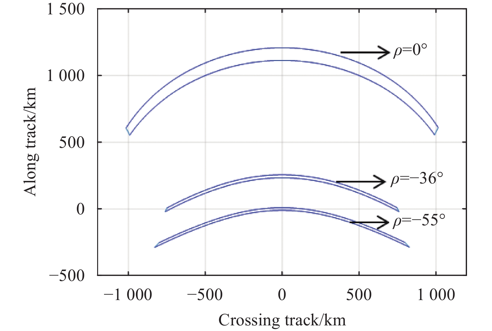
$ \theta = {27.5^ \circ } $ 进行卫星俯仰机动后的分辨率、幅宽等几何参数分析。图9所示为卫星逆时针俯仰55°和卫星不机动时两个方向分辨率的对比,可见由于卫星机动导致相机视线向星下点方向移动,斜距缩短,分辨率提高。图10、图11所示分别为给出相同扫描角度$\; \;\beta = \left[ { - {{60}^ \circ },{{60}^ \circ }} \right] $ 时,卫星绕Y轴逆时针俯仰机动$\; \rho $ 角度后的地面轨迹及幅宽,可见随着卫星俯仰机动角度的增加,幅宽先减小后增大,在$\; \rho = - {36^ \circ } $ 时,幅宽最小为1510 km。
Figure 9. Comparison of GSD between satellite maneuver and non maneuver

Figure 10. Ground trajectory at different pitch angles

Figure 11. Curve of width changes with pitch angle
-
大幅宽、高分辨率、多角度是未来对地遥感的重要发展方向,针对目前穿轨扫描成像体制存在的分辨率退化严重、大气程辐射差异大影响定量化应用等问题,提出了一种基于斜视等距扫描的成像方法,对大幅宽、高分辨率、多角度遥感探测的发展具有参考意义。给出了:(1) 大幅宽斜视等距扫描成像过程中,扫描方向与垂直扫描方向空间分辨率随扫描角度的关系式;(2) 幅宽随扫描角度的关系式;(3) 通过卫星平台俯仰机动,实现多角度观测时分辨率、幅宽关系式。将文中方法应用于某预研星载大视场相机,视场边缘分辨率退化相比穿轨扫描成像体制的9.3倍降低为2.5倍。
同时,注意到斜视等距扫描方式在两个方向分辨率变化规律不同,这主要是由扫描镜扫描引入像旋导致的,像旋会影响遥感图像的解译应用,如何针对这种斜视等距扫描体制进行消旋是载荷设计及影像应用的重点,后续将持续深入研究。
Spaceborne squint isometric scanning imaging
doi: 10.3788/IRLA20210390
- Received Date: 2021-06-09
- Rev Recd Date: 2021-09-28
- Publish Date: 2022-04-07
Fund Project:
The 14th Five-Year Civil Aerospace Technology Advance Pre-research Project
-
Key words:
- wide width /
- low resolution degradation /
- squint isometric scanning /
- cross-track scanning
Abstract: A new spaceborne imaging method based on squint isometric scanning was presented to overcome the problems of resolution degradation and atmospheric radiation difference with scanning angle in traditional cross-track scanning imaging method. Firstly, the principle of this imaging method was introduced, and the geometric imaging model was established according to the theory of geometric optics. Then, based on the geometric imaging model, the relationship between the scanning direction spatial resolution, vertical scanning direction spatial resolution and width with the scanning angle were given. Furthermore, the expressions of resolution and width for multi-angle observation via satellite pitch were derived. Finally, the simulation results of one pre-research spaceborne imager show that the resolution degradation is greatly reduced. When scanning angle is 60°, the edge view resolution is 2.5 times of central field of view far lower than traditional cross-track scanning imaging method 9.5 times. It provides a new solution for wide width imaging and has a certain reference significance for promoting the development of super wide width, high resolution and multi-angle spaceborne remote sensing.


 DownLoad: