


-
光学条纹相机[1-6]是一种具有一维连续高时间分辨和一维高空间分辨的光学探测仪器,其时间分辨可以达到皮秒甚至飞秒量级,空间分辨可以达到微米量级,测量时间窗口可以覆盖纳秒到微秒时间尺度。通过光学条纹相机自身可以对光脉冲的时间波形进行测量,也可以与光学成像镜头相结合而对光脉冲的时空演化过程进行精密测量,还可以与光谱仪进行耦合而对光脉冲的能谱变化过程进行测量。因此,光学条纹相机广泛应用于各种超快瞬态现象研究领域中[7-11],尤其在激光惯性约束聚变研究中是必不可少的诊断设备之一,无论是在神光系列激光器的激光脉冲测量,还是在物理实验中的冲击波测速和黑腔等离子状态探测研究中,都有着十分重要的应用。
然而,当前激光惯性约束聚变研究中所用的光学条纹相机的阴极通常为多碱阴极[12],谱响应范围较宽(230~850 nm),对可见光波段的各种环境光(包括散射光和周围环境杂散光)都会有响应,从而产生较强噪声而淹没待测物理信号或严重影响所测物理信号的信噪比。为解决这一问题,文中通过预置阴极直流高压叠加门控脉冲电压的方法,发展了一种阴极门控光学条纹相机,有效抑制了相机的背景噪声,提升了相机的信噪比。
-
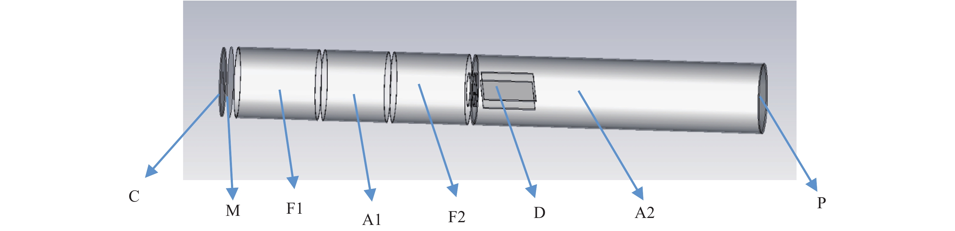
当前国内光学条纹相机所用的扫描变像管通常为轴对称型六电极扫描变像管[13-14 ],其结构如图1所示,主要由阴极(C)、栅极(M)、第一聚焦极(F1)、第一阳极(A1)、第二聚焦极(F2)、第二阳极(A2)、偏转电极(D)和荧光屏(P)组成,这种变像管阴极高压最高可达到−16.5 kV,此时栅极高压可设置为−3.5 kV。

Figure 1. Structure of the streak image tube with six electrodes
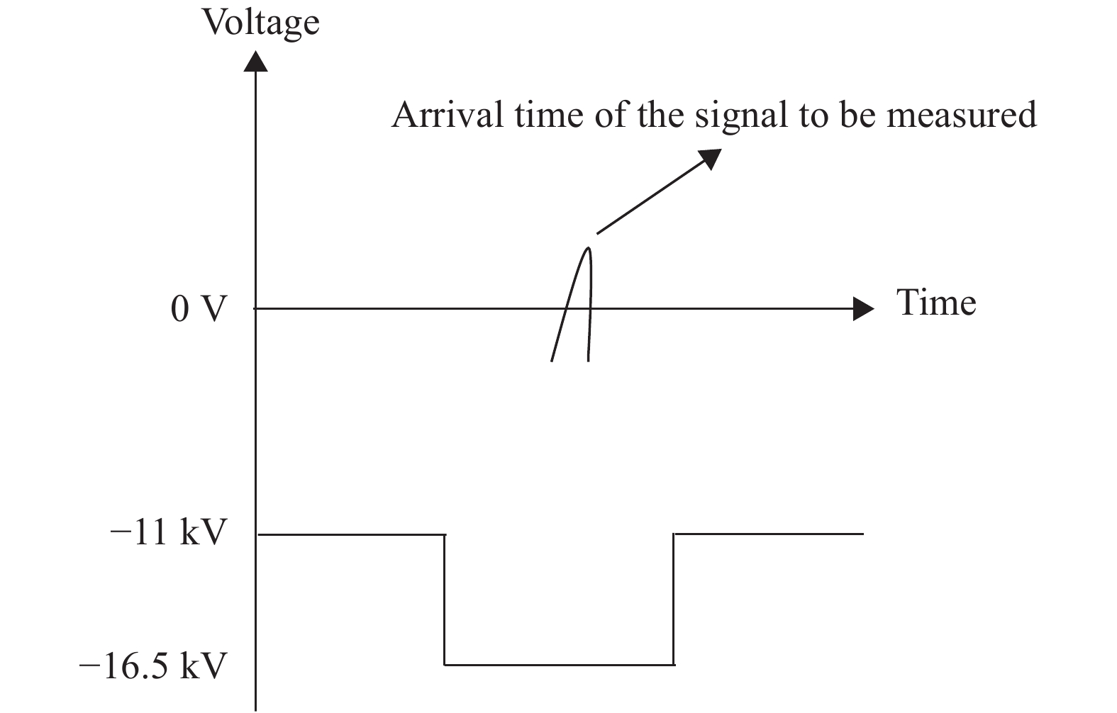
为降低环境杂散光引入的噪声,可使变像管阴极发射电子在无待测信号时处于反向截止状态,而在有用信号到达变像管时,阴极发射电子可被正常聚焦成像和扫描,并到达荧光屏。如此,应使变像管在无待测信号到来时,阴极处电压高于变像管后端某处位置电压,此时变像管的电压加载情况会使各种杂散光引起的阴极发射电子不能到达变像管的荧光屏;而在有用信号到达变像管时,通过在阴极上作用矩形脉冲高压,使变像管的各电极电压达到正常工作时的电压值,可对待测信号辐照光阴极而发射的光电子进行正常聚焦扫描。通常情况下,为使杂散光导致的阴极发射电子处于反向截止状态,一般使阴极电压高于栅极电压,如可将阴极电极电压设置为−3 kV,而为使待测信号使阴极发射的光电子能够正常到达荧光屏并聚焦成像,需要在阴极上施加的矩形门脉冲幅度需高达−13.5 kV,如此高幅度的矩形门脉冲制作难度较大,因此当前条纹相机扫描变像管只加载直流电压,无法有效抑制环境杂散光产生的噪声。
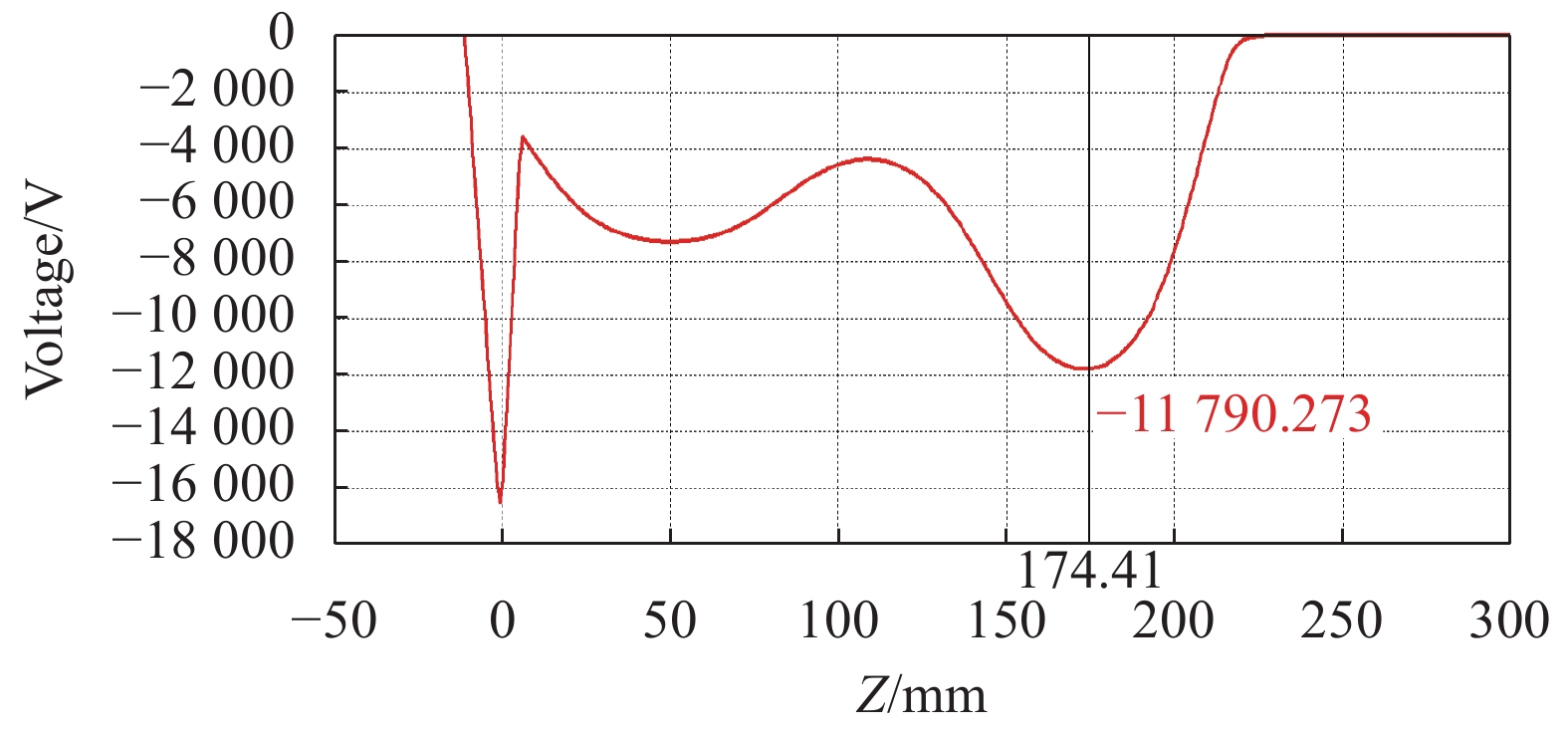
通过对变像管各电极电压加载情况进行详细分析,发现只需使阴极轴心位置处电压高于后端电极F2轴心处电压即可实现对阴极发射电子的反向截止。图2为计算得到的变像管轴心上电压分布情况,可以看出当阴极电压为−16.5 kV时,阴极处轴心位置电压为−16.5 kV,而后端F2电极位置处轴心电压约为−11.79 kV,因此,为使阴极电子能够反向截止,只需使阴极位置处电压高于−11.79 kV即可,如可将阴极电压设置为−11 kV,此时阴极出射的电子就将在F2电极处截止。而为使变像管正常工作,只需施加−5.5 kV的门控高压脉冲即可,显然这种幅度的门控高压脉冲制作相对容易。
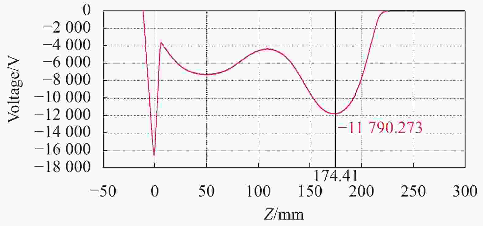
Figure 2. Voltage distribution on the axis of the streak tube
为验证变像管的电子截止情况,分别对阴极加载−16.5 kV和−11 kV电压时变像管的电子运动轨迹进行了计算,如图3所示,图3(a)为变像管阴极加载−16.5 kV时的电子运动轨迹,可以看到此时变像管为正常工作状态,电子能够正常聚焦成像到荧光屏上;图3(b)为阴极电压−11 kV时的电子运动轨迹,可以看出,电子运动到F2电极位置时即被截止,无法到达荧光屏。 因此,根据变像管的这一特性制定了如图4所示的门控技术方案,首先在阴极上施加−11 kV直流电压,其他电极施加正常工作电压,而在待测信号到达阴极时间段内,在阴极上叠加−5.5 kV的矩形门控脉冲,即可使环境光辐照光阴极发射的电子无法到达荧光屏,而降低变像管噪声水平。
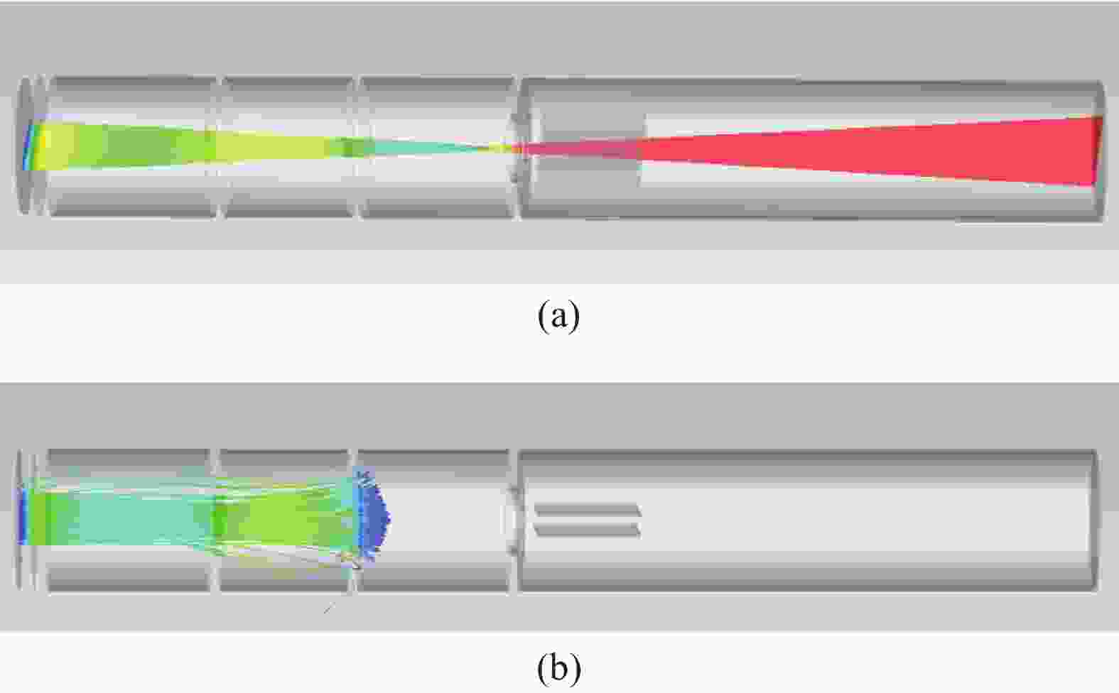
Figure 3. Electron trajectory of the streak tube

Figure 4. Time sequence of the gated photocathode technology
当扫描变像管阴极叠加矩形门控脉冲时,变像管将类似于一种高速快门,此时需要考虑变像管的开启时间τ。如果变像管不能快速开启,会难以同步待测信号到达阴极的时间与矩形门脉冲加载时间,导致待测信号到达相机阴极时,相机依然处于截止状态而无法对有用信号进行测量。理论上扫描管的开启时间τ与阴极面电阻R以及阴栅极间电容C有如下关系:
通过增加多碱导电层薄膜厚度的方法可降低面电阻,但会较大程度上降低入射信号的透过率而降低阴极光谱响应灵敏度。因此,为进一步降低开启时间τ,需要降低阴栅极间电容C。由于阴栅间类似于平板电容器,电容可按下述公式计算:
式中:C为板间电容值;ε为两板间相对介电常数;k为静电力常数;S为阴栅正对面积;d为阴栅间距。介电常数主要为真空介电常数,难以改变,而阴栅间距d的增大会降低变像管的时间分辨率,因此减少阴栅正对面积是主要方法。如图5所示,通过对变像管阴栅电极结构的优化,将阴栅面积减少了5倍以上。最后,为获得超快的阴极高压门控,需尽可能减少传输线长和寄生电感,采用从阴极位置处就近引出高压线的方式使得阴极脉冲高压引出线缩短到了100 mm以下。

Figure 5. Structure of the photocathode and mesh
-
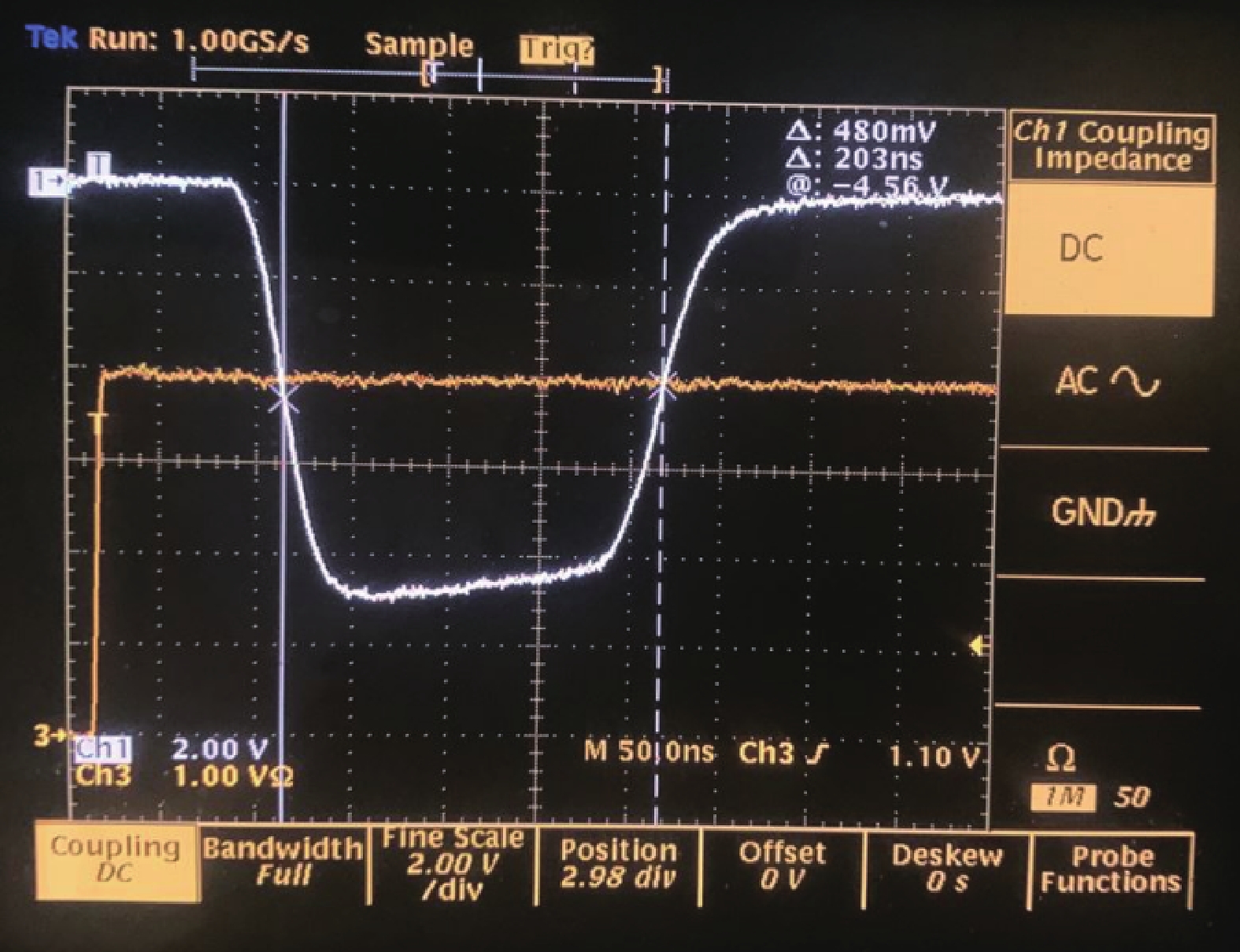
为验证阴极门控技术的可行性以及研究采用阴极门控技术后对相机性能的影响,设计了如下排布的验证实验,如图6所示。以一台阴栅改进型光学条纹相机(OSC)作为实验测试对象,分别测量OSC在门控模式和常规模式下的成像效果,以验证阴极门控技术对于背景噪声的抑制效果。所用的负高压门控脉冲如图7所示,其幅度为−5.5 kV,脉宽约203 ns。此外,实验采用一台DG535脉冲发生器提供三路触发脉冲,其中两路分别用于触发门控脉冲和激光器,并通过调节触发脉冲的延时使激光信号到达阴极时间在门控脉冲加载时间内,另外一路提供给示波器作为触发时间基准。同时,一个光电二极管用于接收短脉冲激光器分束的小部分激光能量,并将波形送到示波器监视激光与门控高压脉冲的时序。

Figure 6. Experimental arrangement of the gated photocathode technology
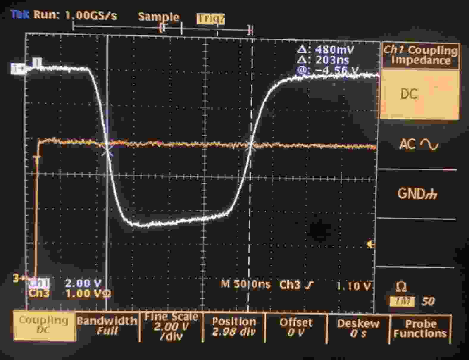
Figure 7. Waveform of the gated pulse
-
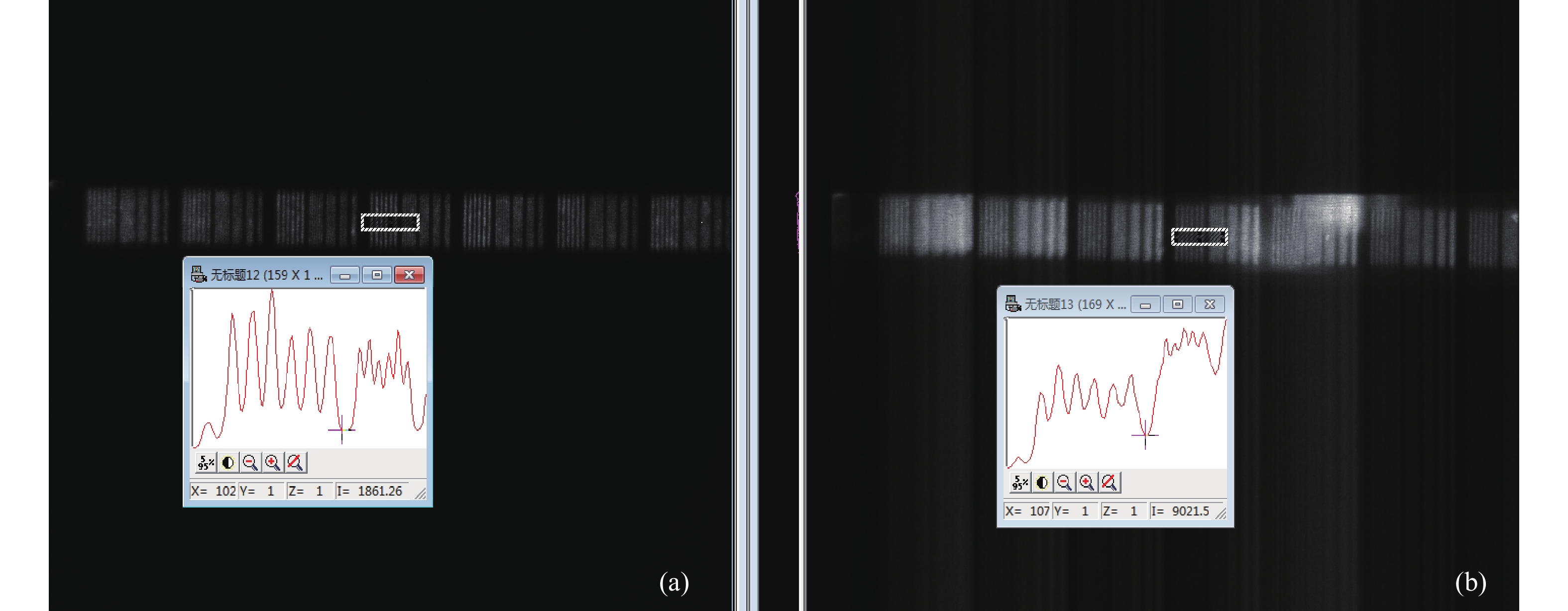
为验证阴极门控技术对于环境噪声的抑制效果,以及研究阴极门控技术对于扫描变像管的成像效果影响,分别在有无门控高压加载阴极情况下(阴极加载门控高压成像时,称为门控模式;阴极加载直流高压成像时,称为常规模式)对相机的噪声水平和空间分辨率进行了测量。在自然环境光照条件下,对施加传统直流高压和采用阴极门控技术两种情况的相机分辨率板图像进行了测量,以验证阴极门控技术对噪声的抑制效果,此时相机处于静态工作模式下,测试结果如图8所示。可以看出,当变像管只加载直流高压时,测试结果如图8(b)所示,环境光给条纹相机的成像带来很强的噪声,测试图像受强环境光影响而变得模糊,严重影响实验数据获取。作为对比,采用203 ns脉宽的阴极高压门控技术做了同样的测试,测试结果如图8(a)所示,测试图像非常干净,可以正常获取相机的分辨率图像,表明203 ns的阴极门控很好地抑制了环境噪声。定义图像信噪比为测量信号计数强度与相邻位置非信号区域强度计数的比值,如图8所示,对白色方框位置处的信噪比作了初步计算比较,在门控模式下,信号强度计数约为6200,噪声计数约为1861,CCD本底计数约为850,计算得出信噪比约为5.29;而在无门控情况下,信号强度计数约为15500,噪声计数约为9000,CCD本底计数约为850,信噪比约为1.80。可见采用阴极高压门控技术在较大程度上降低了背景噪声,提升了相机信噪比,初步的实验结果表明,信噪比至少提升了近2倍。

Figure 8. Tested images in (a)gated and (b)normal mode
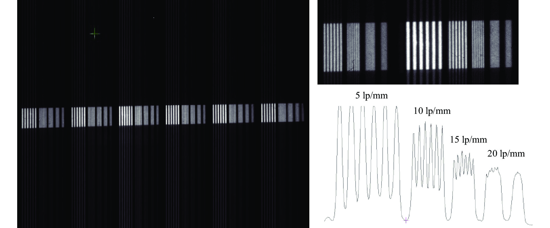
为验证条纹相机在阴极高压门控下的成像效果,在门控模式下对相机的空间分辨率图像进行了细致处理,如图9所示,可以看出相机依然可以获得15 lp/mm的空间分辨率。而施加传统直流高压时,在黑暗环境下测试得到的相机空间分辨率图像如图10所示,可以看出,不使用门控技术时,相机的空间分辨率最高可以达到20 lp/mm。阴极门控技术的使用给空间分辨带来了一定影响,但影响较小,这是由于门控脉冲的纹波导致在门控时间内阴极电压产生波动造成的。
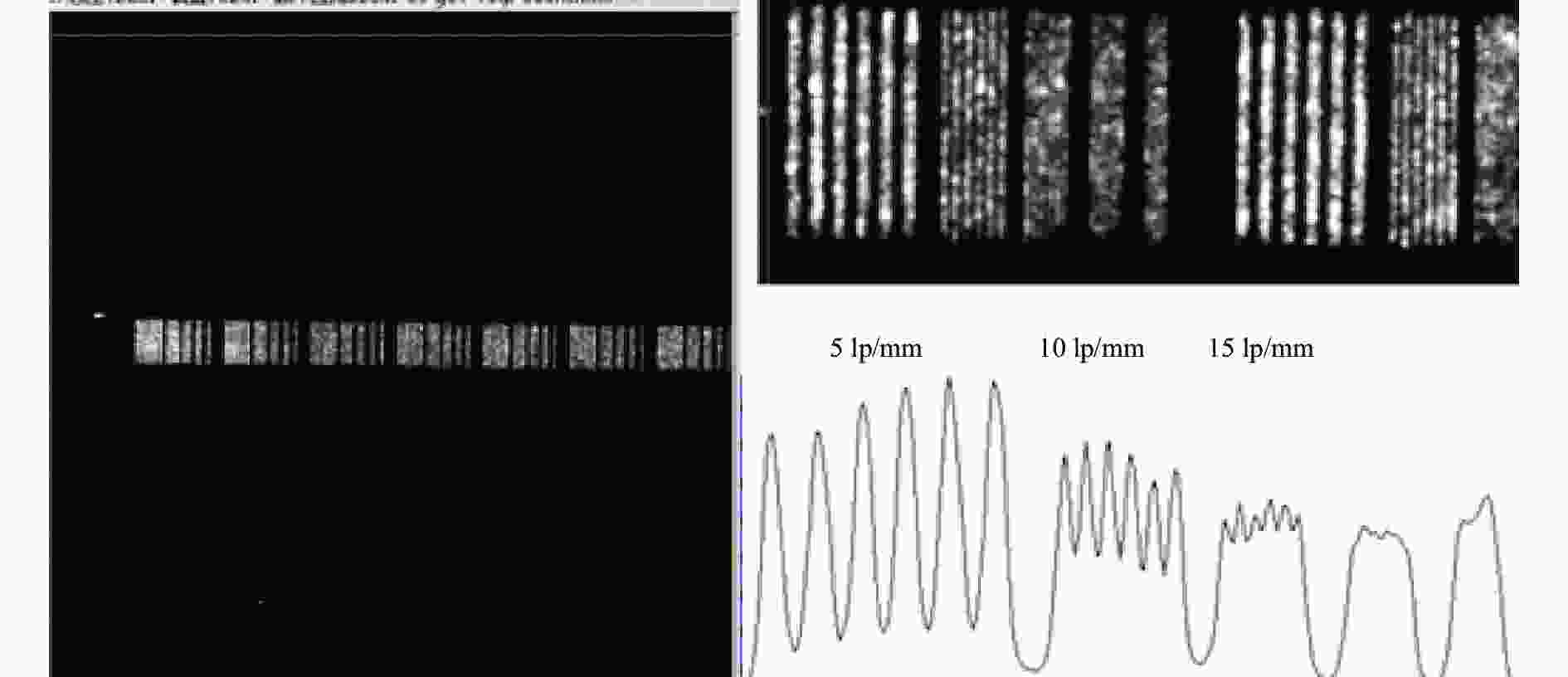
Figure 9. Static spatial resolution in gated mode

Figure 10. Static spatial resolution in normal mode
为证明阴极施加高压门控脉冲对条纹相机动态扫描未产生干扰影响,在采用阴极高压门控的情况下,在动态模式下对相机的动态扫描空间分辨率进行了测试,此时采用激光器发射的激光脉冲辐照光阴极。测试结果如图11所示,可以看出,在动态模式下相机依然获得了清晰的动态空间分辨率图像,最高空间分辨率也达到了15 lp/mm,与静态空间分辨率相同,表明采用阴极高压门控技术没有影响相机的成像效果。
通过以上的验证实验表明,针对当前传统的六电极扫描变像管,通过设计的阴极门控技术,只需采用较低幅值的门控脉冲即可大幅度降低光学条纹相机受环境光辐照而引入的背景噪声,同时,结果表明门控脉冲技术对相机的成像性能影响较小。
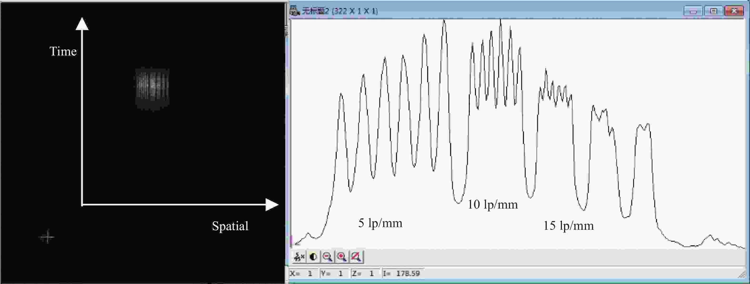
Figure 11. Dynamic spatial resolution in gated mode
-
为了抑制环境光辐照光学条纹相机阴极而引入的背景噪声,基于同轴型六电极变像管,通过在相机变像管阴极上预置阴极直流高压叠加门控脉冲电压的方法设计了阴极门控技术方案,并优化了变像管阴栅电极结构。对门控技术进行了实验验证,结果表明,采用203 ns、−5.5 kV的矩形门控高压脉冲可使相机的信噪比至少提升2倍,同时可使相机的空间分辨达到15 lp/mm。总之,完成了阴极门控技术的可行性验证,将该技术应用于光学条纹相机,可在较大程度上降低光学条纹相机受环境光辐照而引入的背景噪声,从而提升相机的信噪比。
Optical streak camera with gated photocathode
doi: 10.3788/IRLA20210402
- Received Date: 2021-06-15
- Rev Recd Date: 2021-10-02
- Publish Date: 2021-12-31
-
Key words:
- optical streak camera /
- streak image tube /
- gated cathode /
- noise
Abstract: In order to meet the demand for high signal-to-noise ratio and low-noise optical streak camera in inertial confinement fusion (ICF) physical experiment diagnosis, a cathode-gated optical streak camera with six electrodes streak image tube was developed. To suppress the camera noise, a method that loading DC high voltage while superimposing gated high voltage pulse to the photocathode was used. In this way, the streak image tube of the camera was in the normal working state only during the gated pulse loading time, and the electrons emitted by the cathode could be normally focused and scanned. When the control pulse was not loaded, the voltage at the second focusing electrode could be lower than the cathode voltage, so that the photoelectrons emitted by the cathode would be reversely cut off. Therefore, the camera only measured the useful signals that arriving within the gated pulse loading time, thereby effectively suppressing the background noise introduced by the optical streak camera irradiated by ambient light, and improving the camera's signal-to-noise ratio. The verification experiment shows that by loading the gated pulse voltage with amplitude of − 5.5 kV and pulse width of 203 ns on the cathode, the camera noise can be greatly reduced, and the spatial resolution of the camera can be maintained.


 DownLoad: