Volume 51 Issue 3
Apr.  2022
Turn off MathJax
Article Contents

Yang Hang, Chen Ying, Huang Wen, Han Ming, Zhang Xingxing, Jia Yang, Li Bin, Jiang Rong. Trajectory optimization method of variable pitch spiral matrix for intermediate frequency error[J]. Infrared and Laser Engineering, 2022, 51(3): 20210443. doi: 10.3788/IRLA20210443
Citation: Yang Hang, Chen Ying, Huang Wen, Han Ming, Zhang Xingxing, Jia Yang, Li Bin, Jiang Rong. Trajectory optimization method of variable pitch spiral matrix for intermediate frequency error[J]. Infrared and Laser Engineering, 2022, 51(3): 20210443. doi: 10.3788/IRLA20210443

Trajectory optimization method of variable pitch spiral matrix for intermediate frequency error

doi: 10.3788/IRLA20210443
Funds:  Key National Science and Technology Projects(2017ZX04022001);Science and Technology Research Project of Zunyi Science and Technology Bureau(HZ[2020]21);Basic Research Program of Guizhou Province(ZK[2021]272)
  • Received Date: 2021-07-02
  • Rev Recd Date: 2021-09-30
  • Publish Date: 2022-04-07
  • Magnetorheological polishing can efficiently remove low-frequency errors on the surface of optical elements, but it also introduces intermediate-frequency errors. The existence of intermediate-frequency errors has a serious impact on the performance of the optical system, which must be effectively controlled. The commonly used grating trajectories and spiral trajectories were studied. It was found that the regular polishing trajectory caused the convolution process to be inconsistent with the actual removal process, which would introduce symmetrical iterative errors. The iterative error is an important factor in the deterioration of the intermediate frequency error. Based on the research of grating trajectory and spiral trajectory, a trajectory optimization method for variable pitch spiral matrix trajectory was proposed to reduce the intermediate frequency error of optical components. The trajectory retained the advantages of simplicity and ease of the grating trajectory and the spiral trajectory by disrupting the pitch of the spiral matrix trajectory, and also changed the randomness between the trajectory lines. Through the power spectrum analysis of the surface shape before and after processing, it was verified that the trajectory can effectively reduce the intermediate frequency error of the surface, and the intermediate frequency convergence efficiency of the grating line and the spiral line is comprehensively improved by 26.59%.
  • [1] Wan S, Wei C, Hu C, et al. Novel magic angle-step state and mechanism for restraining the path ripple of magnetorheological finishing [J]. International Journal of Machine Tools and Manufacture, 2021, 161(162): 103673.
    [2] Li Xiaoyuan, Gao Wei, Tian Dong, et al. Study on cleaning of residual from magnetorheological finishing (MRF) of potassium dihydrogen phosphate (KDP) crystal surface (English) [J]. Infrared and Laser Engineering, 2018, 47(S1): S120006.
    [3] Liu J, Li X, Zhang Y, et al. Predicting the Material Removal Rate (MRR) in surface Magnetorheological Finishing (MRF) based on the synergistic effect of pressure and shear stress [J]. Applied Surface Science, 2020, 504(2): 144492.
    [4] Nie M, Cao J, Li J, et al. Magnet arrangements in a magnetic field generator for magnetorheological finishing [J]. International Journal of Mechanical Sciences, 2019, 161(10): 105018.
    [5] Pohl M, Kukso O, Boerret R, et al. Mid-spatial frequency error generation mechanisms and prevention strategies for the grinding process [J]. Journal of the European Optical Society-Rapid Publications, 2020, 16(1): 19. doi:  10.1186/s41476-019-0123-2
    [6] Yang X, Hao L, Chen J, et al. Improved imaging quality of cluster LiDAR by optimizing laser energy distribution using an effective optical approach [J]. Optics Communications, 2020, 460(4): 125181.
    [7] Huang X, Deng X, Guo H, et al. Small-scale self-focusing assessment using PSD Shannon entropy of a 3ω process in a high-power laser facility [J]. Fusion Engineering and Design, 2020, 151(2): 111410.
    [8] Sharma R, Singh M, Sharma R. Recent advances in STED and RESOLFT super-resolution imaging techniques [J]. Spectrochimica Acta Part A: Molecular and Biomolecular Spectroscopy, 2020, 231(4): 117715.
    [9] Lai Luwen, Liu Zhigang, Jiao Xiang, et al. Suppression of mid-spatial-frequency errors in optical elements by polishing with compound swing multi-link mechanism [J]. Chinese Journal of Lasers, 2019, 46(11): 1102001. (in Chinese)
    [10] An Qichang, Zhang Jingxu, Yang Fei, et al. TMT M3 mirror figure measurement with slope method [J]. Infrared and Laser Engineering, 2015, 44(6): 1884-1889. (in Chinese)
    [11] Zhao Q, Zhang L, Fan C. Six-directional pseudorandom consecutive unicursal polishing path for suppressing mid-spatial frequency error and realizing consecutive uniform coverage [J]. Applied Optics, 2019, 58(31): 8529-8541. doi:  10.1364/AO.58.008529
    [12] Qiao Licheng, Zhang Jing, Fu Xiuhua, et al. Research on mid-frequency error suppression of optical surface based on pseudo-random Rose trajectory [J]. Laser & Infrared, 2019, 49(11): 1369-1373. (in Chinese)
    [13] Chen Ke. Study on the optimal algorithm and its application based on the theory of entropy [J]. Transactions of Csice, 2004, 22(3): 273-278. (in Chinese)
    [14] Xie Hailong, Xu Chenyang, Wang Qinghui, et al. Toolpath planning and process simulation for robot-assisted freeform surface polishing [J]. Automation & Information Engineering, 2019, 40(6): 1-7. (in Chinese)
    [15] Li Zhigang, Bao Zhenjun, Zhu Heng, et al. Restraining mid-spatial-frequency error of large-size off-axis parabolic mirrors by multi-tool NC polishing [J]. High Power Laser and Particle Beams, 2018, 30(6): 41-46. (in Chinese)
    [16] Elson J M, Bennett J M. Calculation of the power spectral density from surface profile data [J]. Applied Optics, 1995, 34(1): 201-208. doi:  10.1364/AO.34.000201
    [17] Han Xiaolei, Zhang Rongzhu. Optimizing method of machining paths for reducing ripple errors [J]. High Power Laser and Particle Beams, 2019, 31(11): 20-25. (in Chinese)
    [18] Shen Zhengxiang, Wang Zhanshan, Ma Bin, et al. Specifying surface roughness of optical film substrate using the power spectral density [J]. Optical Instruments, 2006, 28(4): 141-145. (in Chinese)
  • 加载中
通讯作者: 陈斌, bchen63@163.com
  • 1. 

    沈阳化工大学材料科学与工程学院 沈阳 110142

  1. 本站搜索
  2. 百度学术搜索
  3. 万方数据库搜索
  4. CNKI搜索

Figures(12)  / Tables(1)

Article Metrics

Article views(213) PDF downloads(44) Cited by()

Related
Proportional views

Trajectory optimization method of variable pitch spiral matrix for intermediate frequency error

doi: 10.3788/IRLA20210443
  • 1. School of Engineering, Zunyi Normal University, Zunyi 563006, China
  • 2. Institute of Mechanical Manufacturing Technology, China Academy of Engineering Physics, Mianyang 621900, China
  • 3. Wuhan National Laboratory of Optoelectronics, Huazhong Institute of Optoelectronics Technology, Wuhan 430073, China
Fund Project:  Key National Science and Technology Projects(2017ZX04022001);Science and Technology Research Project of Zunyi Science and Technology Bureau(HZ[2020]21);Basic Research Program of Guizhou Province(ZK[2021]272)

Abstract: Magnetorheological polishing can efficiently remove low-frequency errors on the surface of optical elements, but it also introduces intermediate-frequency errors. The existence of intermediate-frequency errors has a serious impact on the performance of the optical system, which must be effectively controlled. The commonly used grating trajectories and spiral trajectories were studied. It was found that the regular polishing trajectory caused the convolution process to be inconsistent with the actual removal process, which would introduce symmetrical iterative errors. The iterative error is an important factor in the deterioration of the intermediate frequency error. Based on the research of grating trajectory and spiral trajectory, a trajectory optimization method for variable pitch spiral matrix trajectory was proposed to reduce the intermediate frequency error of optical components. The trajectory retained the advantages of simplicity and ease of the grating trajectory and the spiral trajectory by disrupting the pitch of the spiral matrix trajectory, and also changed the randomness between the trajectory lines. Through the power spectrum analysis of the surface shape before and after processing, it was verified that the trajectory can effectively reduce the intermediate frequency error of the surface, and the intermediate frequency convergence efficiency of the grating line and the spiral line is comprehensively improved by 26.59%.

    • 磁流变抛光技术(MRF)具有加工面形精度高[1]、表面粗糙度小[2]、加工过程确定性高、表面损伤小[3]、加工过程不产生新的损伤等优点[4]。然而,磁流变加工后的光学元件表面往往包含较多的中频误差[5],会严重影响光学元件的成像质量[6]。为了满足强激光系统[7]和高分辨率成像系统对光学系统中元件表面中频误差提出的要求[8],如何减少磁流变抛光加工过程中产生的中频误差成为高精度光学制造需要解决的关键问题[9]。综合国内外文献来看,国外实现了对中频误差的有效控制,但核心技术保密[10]。国内研究机构已经认识到抛光轨迹对中频误差的重要影响[11],同时也开展了一些研究来针对磁流变抛光中的中频误差,但大部分是借鉴于国外的研究思想,如:伪随机轨迹[12],同时也提出了如基于熵增理论设计随机加工路径等新方法[13]。但这些研究并没有完全揭示抛光轨迹过程中光学元件中频误差的修整机制,也没有有效地控制中频误差。如何对加工轨迹进行优化[14],在简单易行的基础上实现中频误差的收敛是中频误差控制中的重要问题[15]。文中分析了光栅线抛光轨迹和螺旋线抛光轨迹对正弦面面形中频误差的影响,进一步提出了变距的螺旋矩阵加工轨迹,并对加工后的面形进行功率谱密度分析[16],对因轨迹引起的特定波纹误差进行了有效控制[17]

    • 劳伦斯利弗莫尔国家实验室(LLNL)在研制国家点火装置(NIF)中,按照具体的面形误差的频率域空间长度L将其全频段误差进行划分,中频误差带(0.12 mm< L <33 mm)由较大波长的表面起伏构成,表现为波纹状,所以中频误差也叫波纹误差。中频误差使光线在传播过程中产生小角度的散射,在相面产生相变、耀斑等问题,降低了成像质量,因此期望能够抑制中频误差。

      中频误差的评价参数有很多,如均方根值(RMS)、峰谷值(PV)及高度分布函数等,只能描述轮廓在垂直方向上的相对偏离,无法提供其斜率、形状和尺寸等信息,也无法描述它们的频率及规律。因此,需要空间函数来表征所有波长及空间大小的特征,即凹凸体的形状。而功率谱密度函数PSD满足了这个特性。其定义如下:

      式中:L为平均的频谱范围;Z(k)为高度尺寸;Z(x, y)为傅里叶变换的频谱函数。

      根据公式(2)可以对PSD进行离散估计[18]

      式中:L为平均频谱范围;N为取样点数; Δx为取样间隔;W(n)为窗口函数;K(n)为边界因子。

    • 磁流变抛光中,采用抛光轮带动抛光液在梯度磁场下形成抛光缎带,实现对光学元件的抛光。抛光缎带对光学元件表面的去除量是抛光轨迹与去除函数的卷积。工件最终面形修整的情况由初始面形和去除量决定。去除量是去除函数与驻留时间沿加工轨迹的二维卷积,如公式(3)所示。因此,加工轨迹是决定最终面形空间误差频率的关键因素。

      式中:E(xi, yi)表示光学元件在(xi, yi)点的去除量;Τ(ξj, ηj)表示在第j个轨迹点驻留的时间;N表示轨迹点的个数;R(xiξj, yiηj)表示去除函数在位于第j个轨迹点时单位时间内对元件处于(xi, yi)点的去除量。

    • 由规则的螺旋轨迹和光栅轨迹的中频影响分析可知,规则轨迹会在面形表面留下周期性的纹路,并反映在PSD曲线上,不利于中频误差的修正。针对规则轨迹的上述问题,提出在光栅线加工轨迹和螺旋线加工轨迹的基础上打乱抛光轨迹的规则性,使得误差能够均匀分布在面形表面。

    • 行距(螺距矩阵轨迹线之间的距离)设为x方向,列距(沿抛光轮的进给距离)设为y方向。初始面形矩阵如公式(4)所示。

      对于光栅线的行距$\Delta x$ 和列距$\Delta {{y}}$引入随机量,使其成为随机光栅行距${\tilde x_r}$与步距$ {\tilde y_c} $。即:

      进一步,对于螺旋线s

      式中:$ \alpha ,\beta $为极坐标参数;$ \varphi ,r $为极坐标。对于从初始位置$\left( {{x_0},{y_0}} \right)$出发的螺旋线,引入随机量,使得:

      求解公式(4)~(6)可以建立螺旋矩阵轨迹。其具有螺旋轨迹的基本特性,同时引入了随机光栅信息,使得轨迹具有随机性。

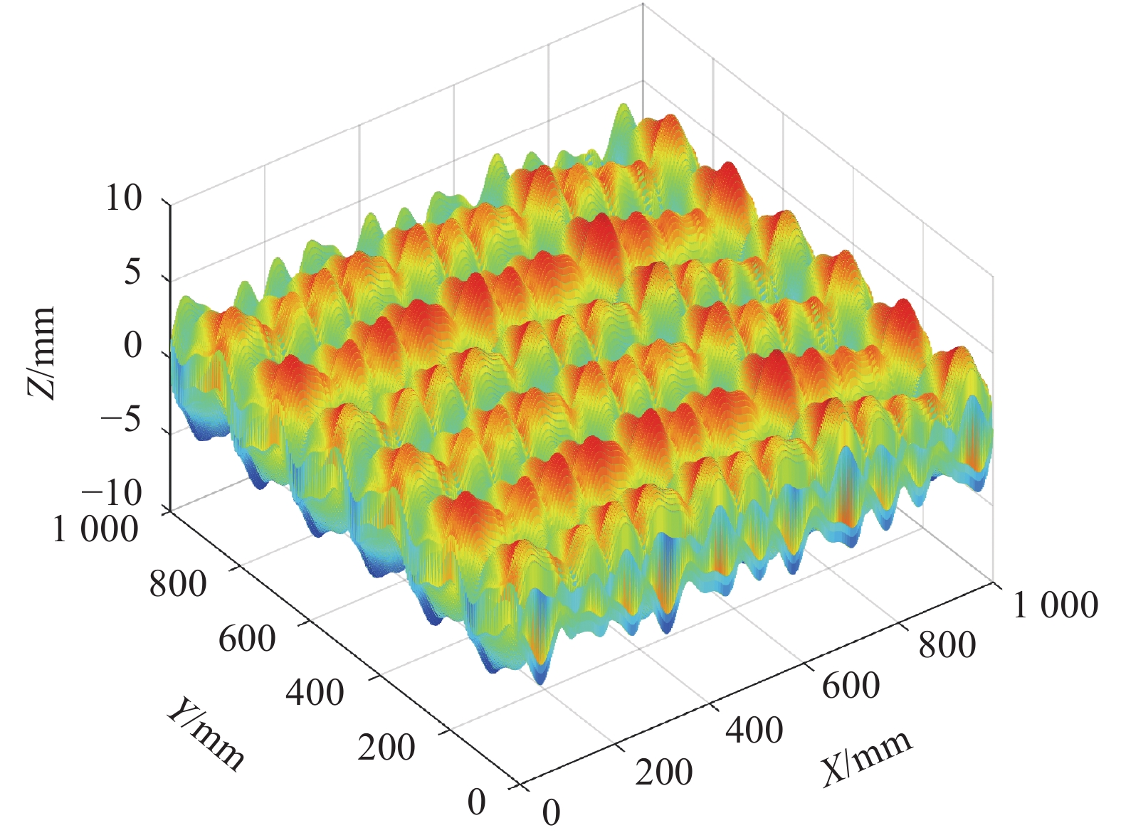
    • 图1为磁流变抛光的初始面形,其由10、70、150、300 Hz四个频率成分组成正弦信号,各频率对应的振幅分别为0.8、1.2、1.5、0.5 mm,其表达式为:

      Figure 1.  Initial surface error distribution

      图2为磁流变抛光的去除函数,其主要的几何参数有长度(参考尺度为20 mm)、宽度(参考尺度为12 mm)和束径(最小外接圆的直径,参考尺度为15 mm)。

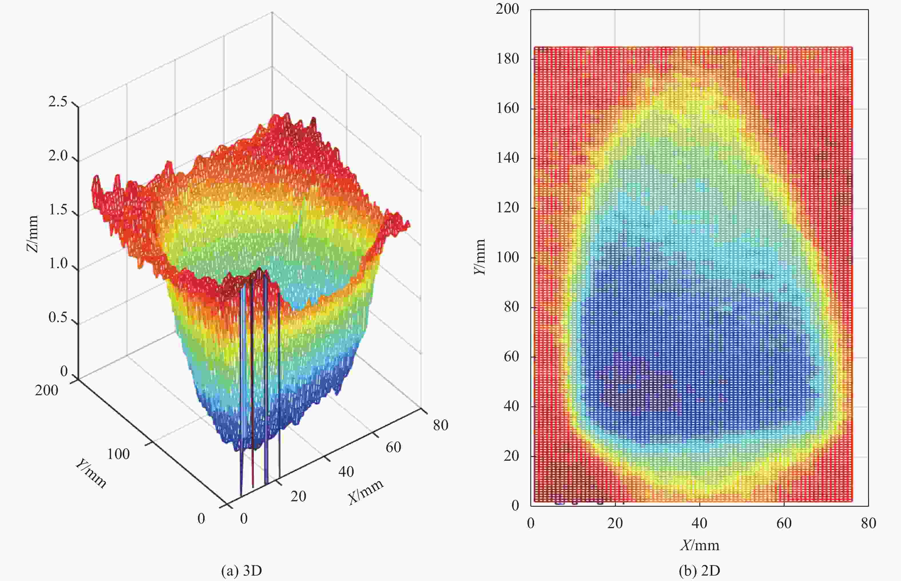
      Figure 2.  (a) 3D and (b) 2D shapes of magnetorheological finishing removing function

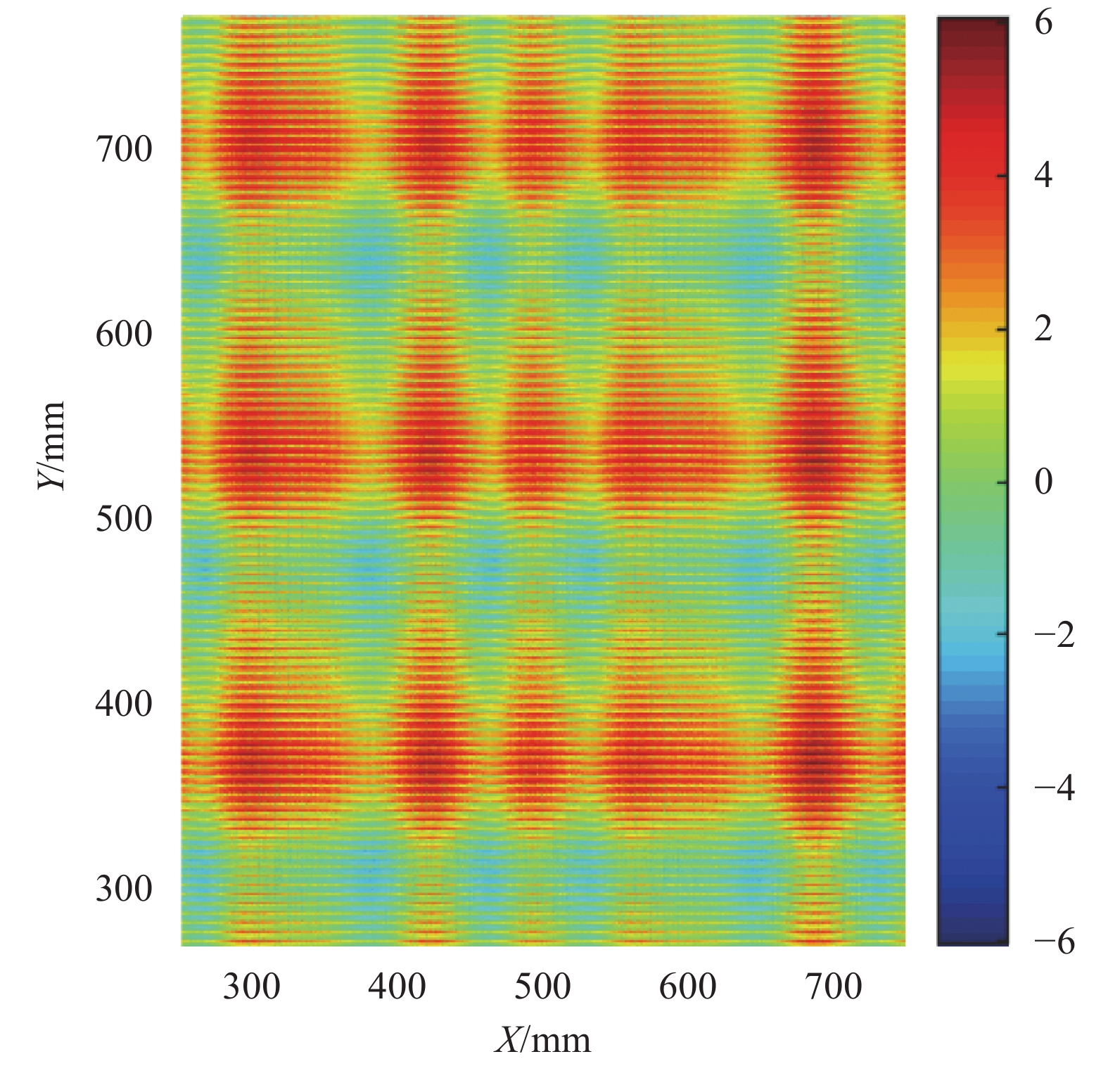
      图3为确定性加工中常用的ρ-θ螺旋线抛光轨迹。图4为初始面形图,将初始正弦面形减去驻留时间与去除函数按照公式(3)进行的二维卷积得到ρ-θ螺旋线抛光后的面形如图5所示。可以发现按照ρ-θ螺旋轨迹抛光后的面形存在中心过抛的现象。

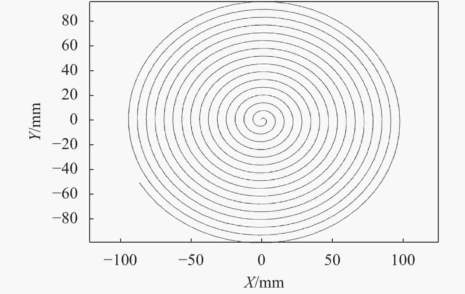
      Figure 3.  Spiral trajectory

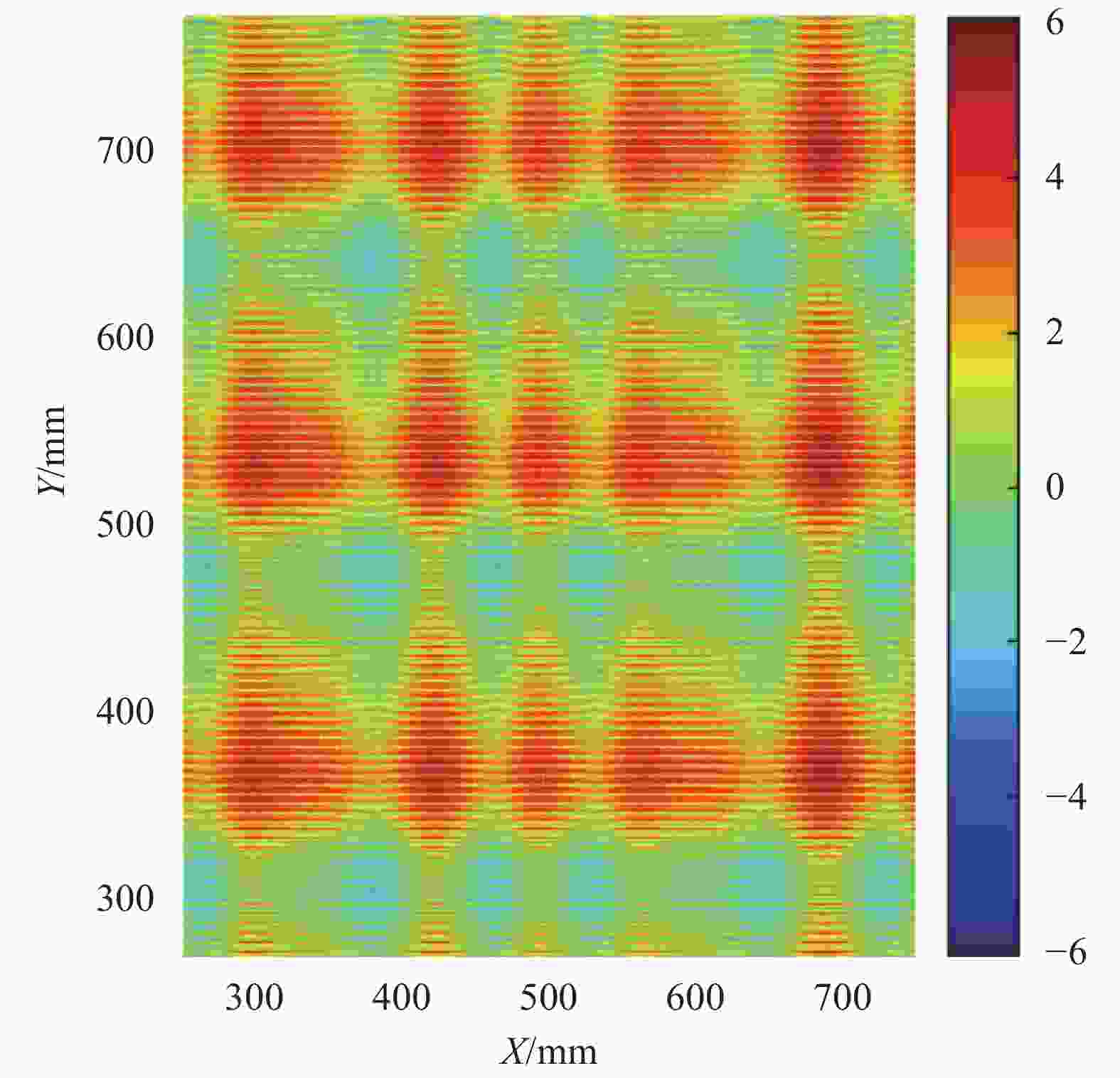
      Figure 4.  Initial surface

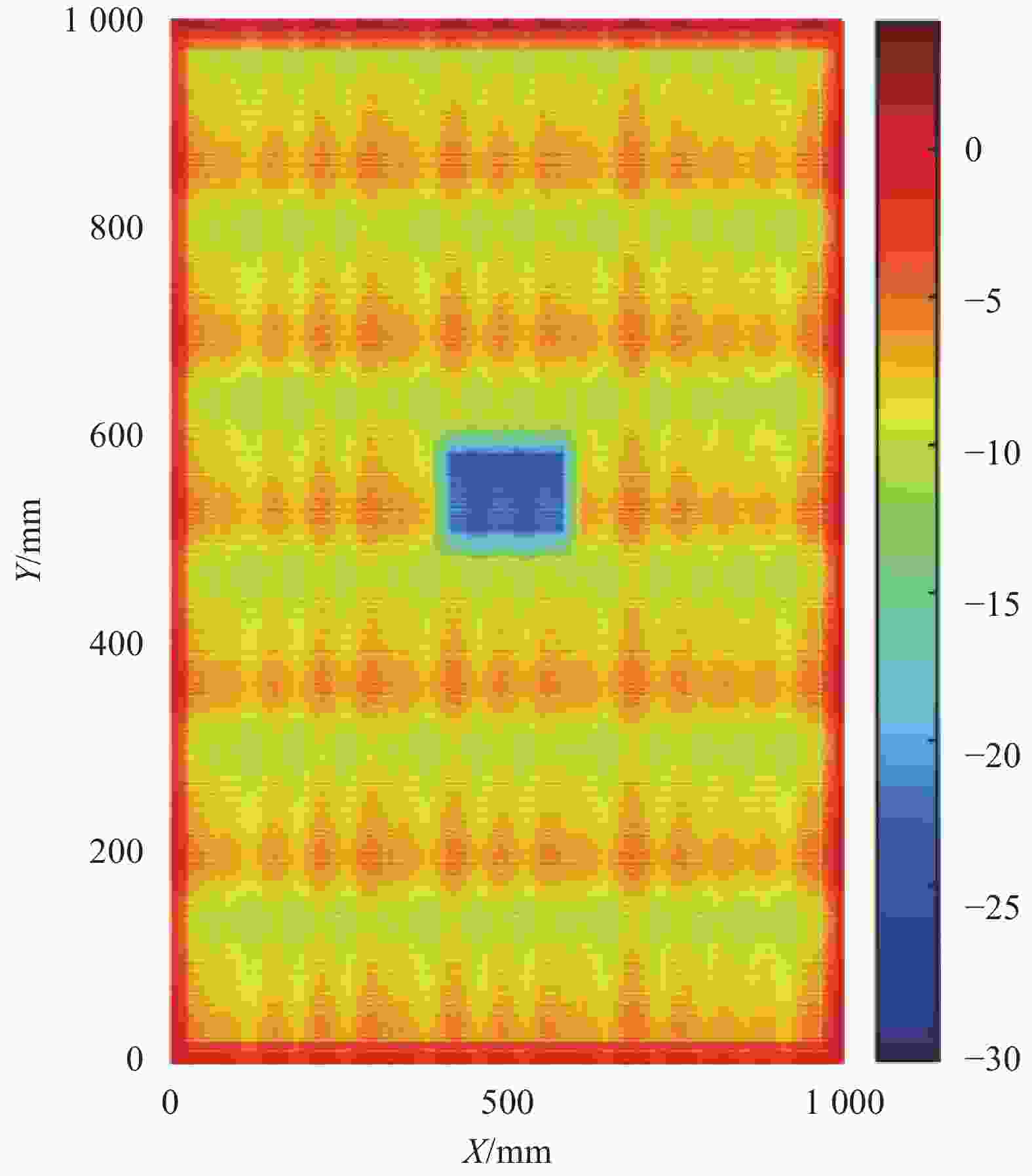
      Figure 5.  Spiral polishing rear shape

      根据公式(2)在频域对其误差频率的变化进行分析,计算得到螺旋轨迹抛光前后的面形沿x方向和y方向的一维PSD曲线,计算结果如图6所示。

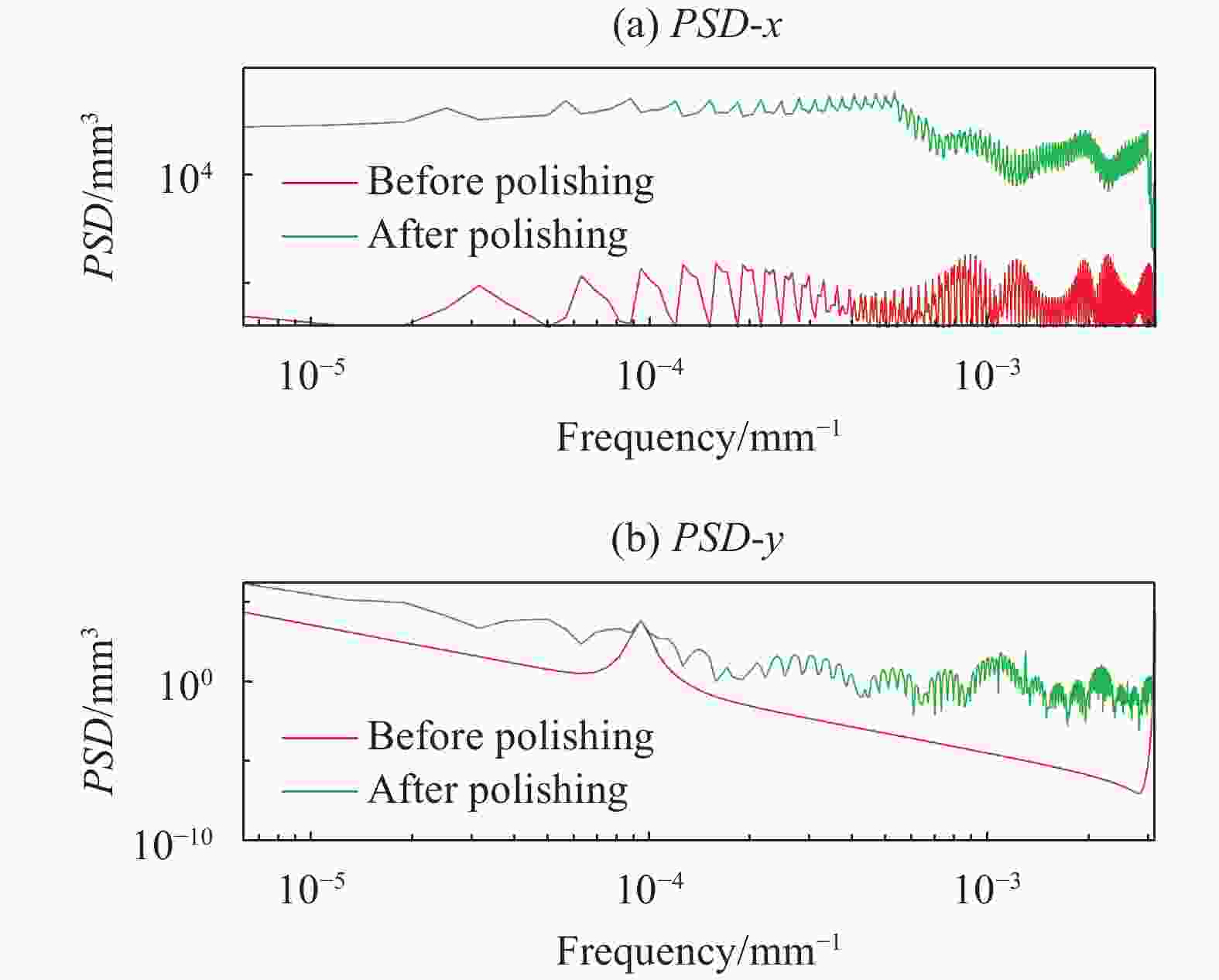
      Figure 6.  PSD analysis of the (a) x direction and (b) y direction before and after the spiral polishing

      图6为螺距为10 mm、进给距离为5 mm时对正弦面形进行加工前后的面形PSD曲线,可以发现沿着该轨迹抛光可以对4 mm处的尖峰误差进行有效收敛,但同时也引入了很多比较碎的误差频率。ρ-θ螺旋线加工轨迹,可以消除圆形工件中的非对称性误差;极坐标加工的方式使得加工设备对X轴和Y轴的行程要求有所降低,加工时不需要换向,但同时也存在工件转动不平稳、中心转速过快而造成中心过抛等缺点。

    • 图7为磁流变抛光加工中常用的光栅轨迹,由于轨迹有抛光头的进给距离和光栅的栅距,材料去除量是不均匀分布的。图8为初始面形,图9为光栅加工后的面形。

      Figure 7.  Grating trajectory

      Figure 8.  Initial surface

      Figure 9.  Raster line processing rear shape

      图10为在抛光头的进给距离为5 mm、光栅的栅距为10 mm时抛光前后的功率谱密度曲线,可以发现等间距光栅线会在频谱上存在一个尖峰误差,而且尖峰误差对应的频率是轨迹线行距对应的频率。由对功率谱密度函数的描述可知,合格的光学元件表面频谱连续且光滑,尖峰误差的出现对光学系统有不良影响。如果以LLNL对中频误差的划分方式来看,磁流变抛光的栅距为5 mm,实际加工过程中栅距的范围是0.12 mm< x <33.3 mm,那么出现对应的尖峰误差频率恰好出现在中频误差范围之内。所以光栅轨迹带来的尖峰误差是中频恶化的一个关键因素。

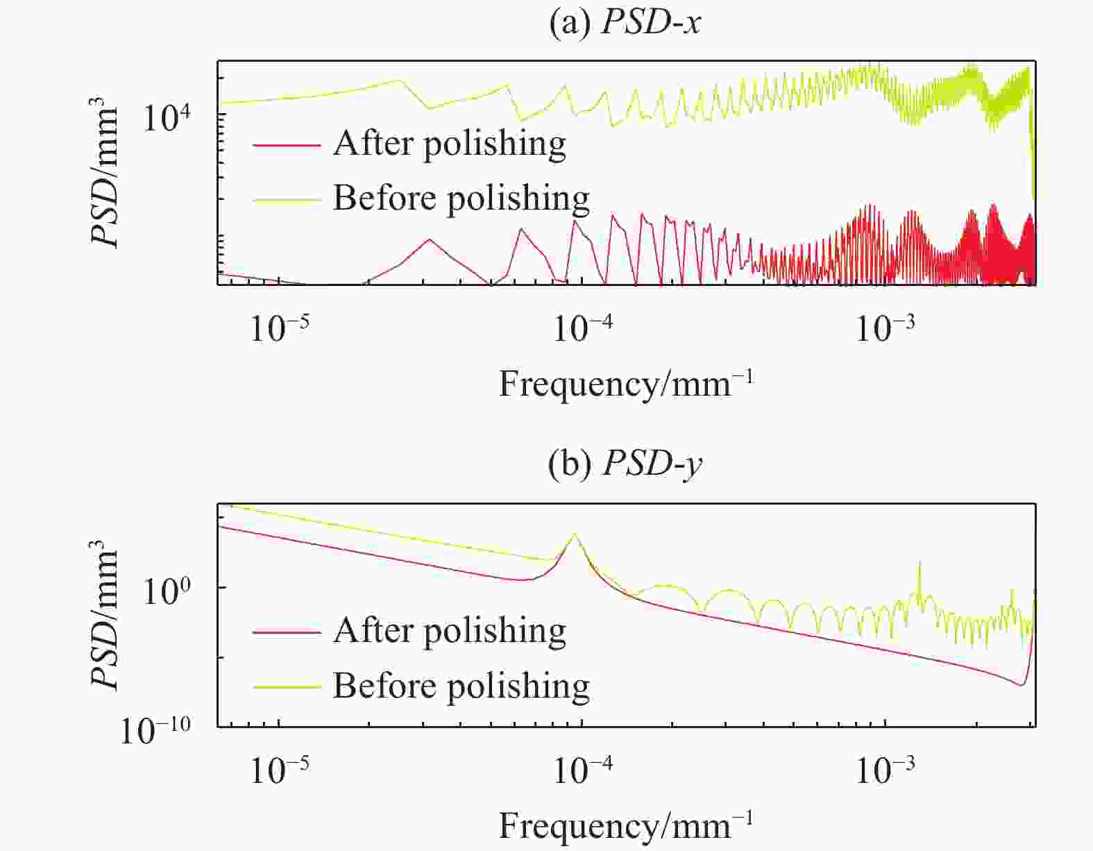
      Figure 10.  PSD analysis in the (a) x direction and (b) y direction before and after the grating line polishing

      光栅线轨迹加工时工件做周期往复运动,抛光头沿着工件的直径做进给运动,可应用于所有平面的加工。对于光栅线轨迹,抛光模仅有X轴和Y轴运动,要求加工设备行程要覆盖整个光学表面,而且加工时抛光头要反复换向,增加了加工时间。

      因此,可以看出,规则抛光轨迹都是离散间隔分布的,轨迹无法遍历每个误差点,导致卷积过程与实际去除的不一致,会带来对称的迭代误差。

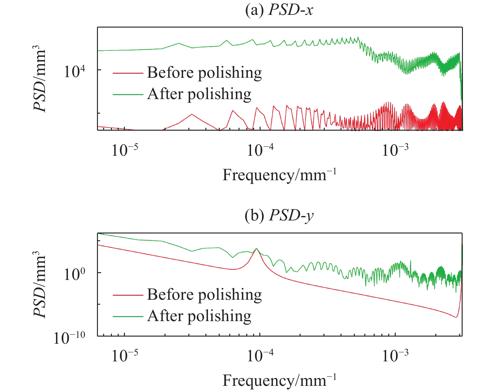
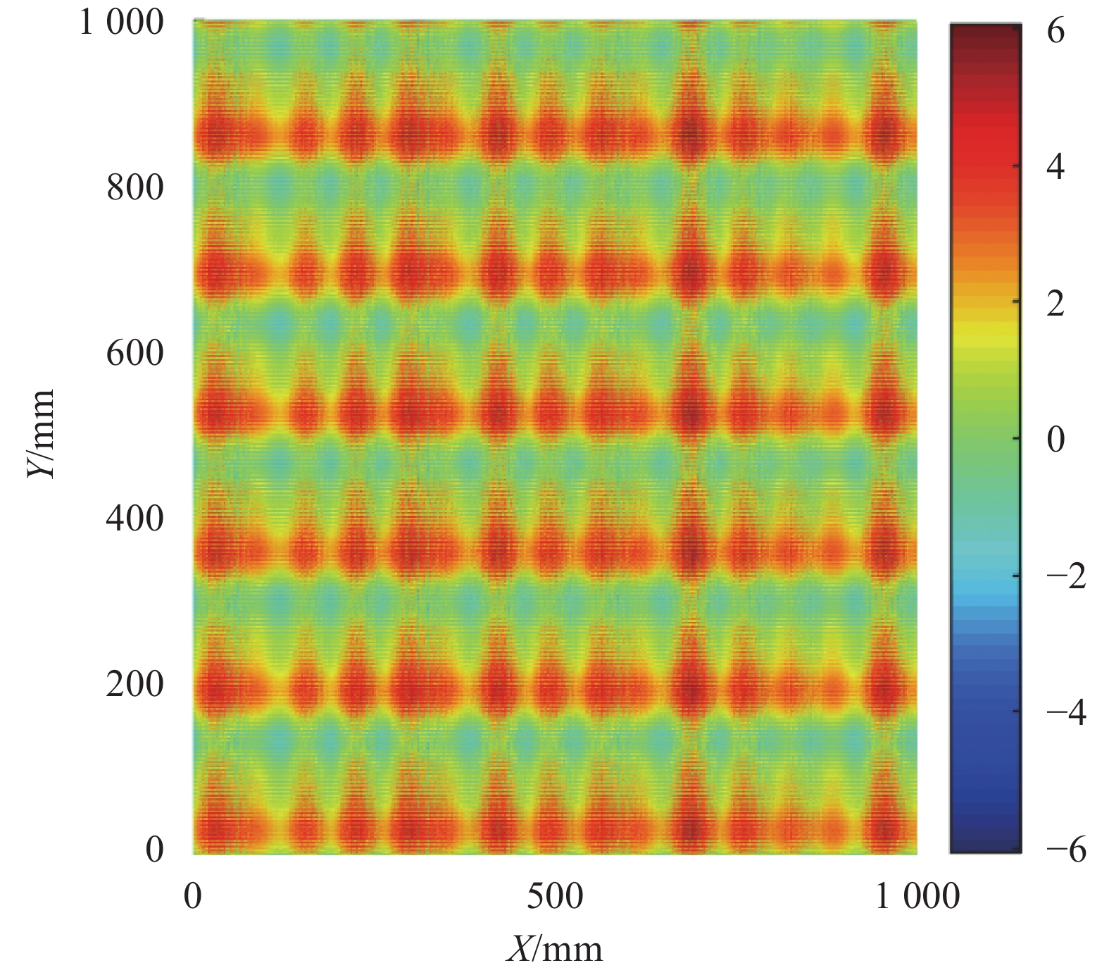
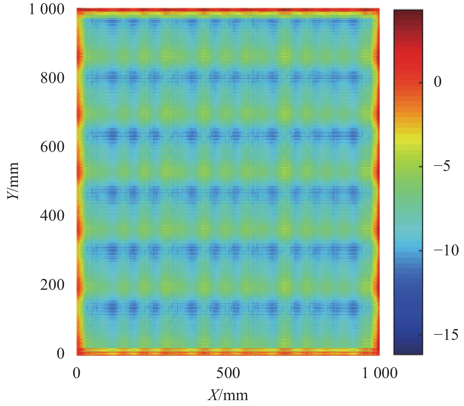
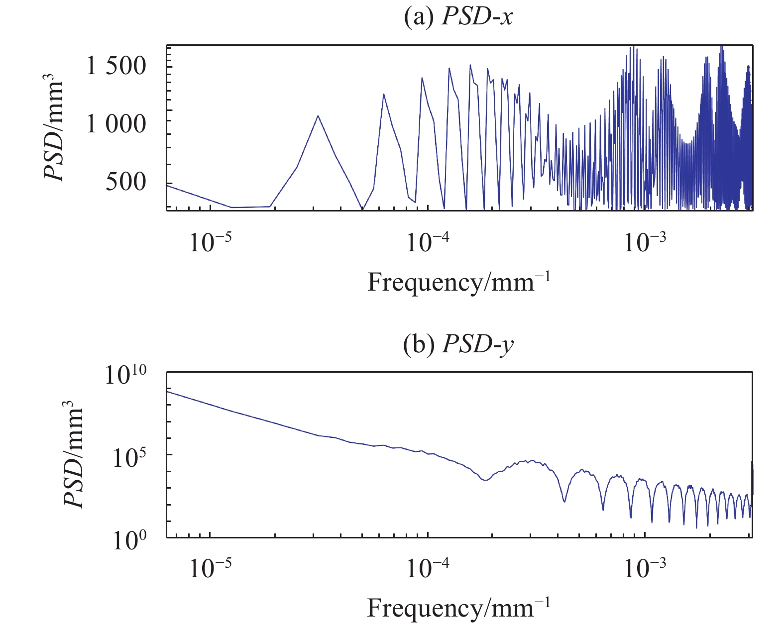
    • 根据公式(4)将螺旋矩阵轨迹加上一个实际位置量10%的白噪声随机扰动后对面形进行加工,再分别与传统螺旋线轨迹加工、光栅轨迹加工进行对比,分析其优化效果。变距螺旋矩阵轨迹加工同一面行前后结果如图11所示。对其进行两方向的功率谱密度分析可以分别得到xy方向的PSD,如图12所示。

      Figure 11.  (a) Before and (b) after polishing with raised spiral matrix trajectory processing

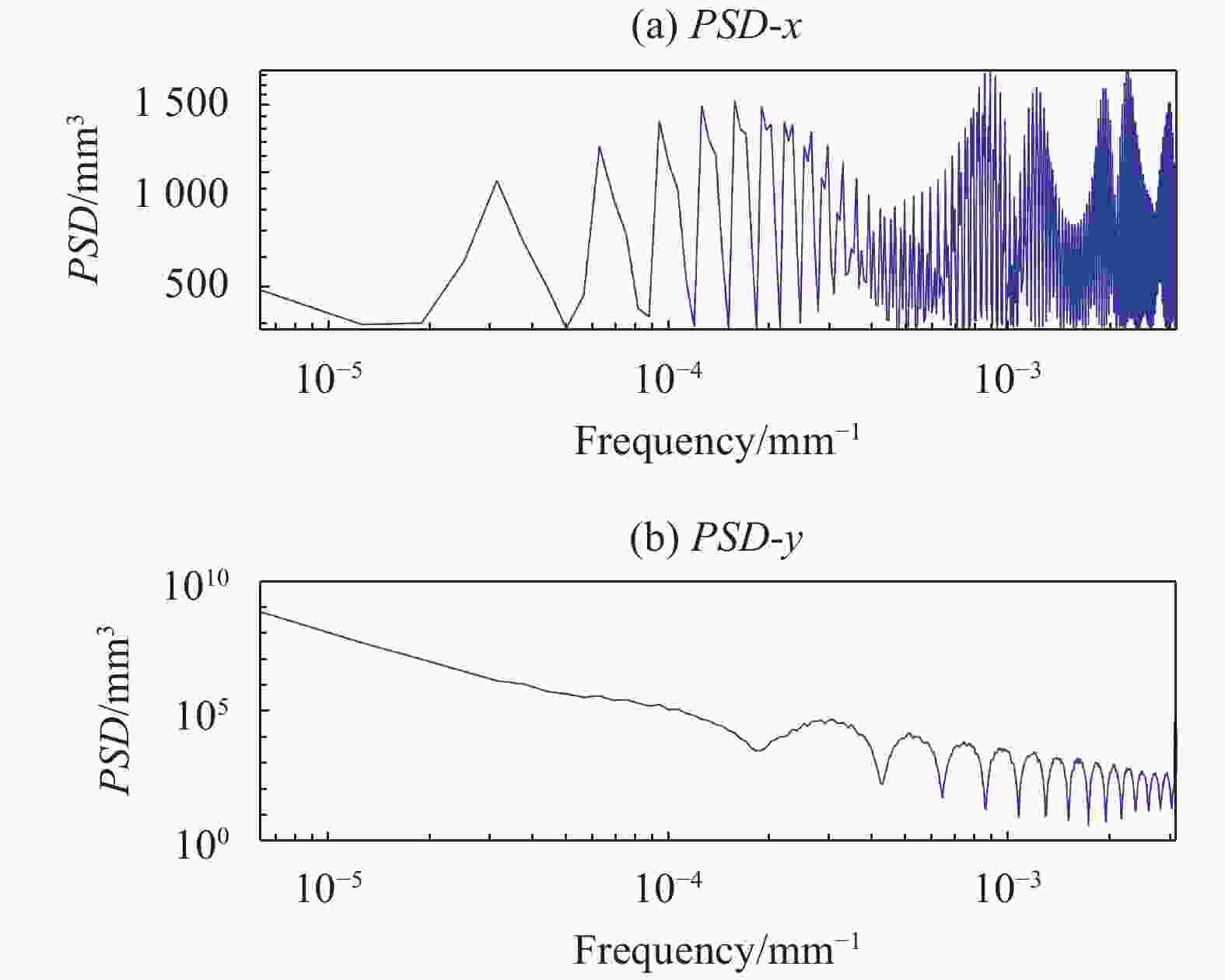
      Figure 12.  PSD analysis of the width screw matrix trajectory (a) x direction (b) y direction PSD analysis

      图12所示,面形在不规则的螺旋矩阵轨迹抛光后的功率谱密度曲线比螺旋线和光栅线的功率谱密度曲线整体下移,在10−4 mm−1处和10−3 mm−1处的频率误差均能够得到抑制。具体情况如表1所示。

      DirectionKey
      frequency
      PSD before
      optimized
      After polishingImprovement
      RasterSpiralNew method
      PSDConverging efficiencyPSDConverging efficiencyPSDConverging efficiency
      x 9.43E-05 9735 1361 86% 1278 87% 1125 88% 2.00%
      y 9.43E-05 8292 8167 2% 7843 5% 0.00001893 100% 96.54%
      x 1.29E-03 8888 1152 87% 1235 86% 394.6 96% 8.99%
      y 1.29E-03 96.44 1.34E-05 100% 0.00001064 100% 1.12 99% −1.16%

      Table 1.  Comparison before and after PSD optimized

      可见,对于两个关键频率,x、y两个方向共计四个关键点位PSD数据,相对于传统抛光轨迹,文中所提方法收敛率较传统光栅轨迹和螺旋线轨迹的平均水平分别提高了2.00%、96.54%、8.99%、−1.16%。总体来说,对于观测点位收敛效率比传统方法提高率不太明显,但是通过随机优化,其绝对收敛效率已经很高。另外,在观测点外总体PSD的平滑程度已经得到了改善。观测点位处的峰值在抛光后已经出现了频率漂移的现象,说明文中的随机优化方法改善了原有频率点的中频误差。第四个点位较传统方法略有下降,因为在这一频率观测点位关键频率被平滑,不至于产生峰值,其PSD绝对值虽然增加,但是平滑程度有明显改善。总体来讲,通过不规则的螺旋矩阵轨迹加工面形可以降低面形表面的中频误差,较传统方法绝对收敛率提高了26.59%。

    • 文中针对磁流变加工中存在的卷积轨迹中频效应现象,对加工轨迹进行优化分析,获得的主要结论如下:(1)建立了轨迹中频正向影响分析;(2)对常见的规则光栅轨迹和螺旋线轨迹加工进行了分析,发现了规则轨迹对中频误差的影响机理;(3)提出了不规则螺旋矩阵轨迹优化方法,由于打乱了螺距,使得该加工轨迹在结合了光栅轨迹和螺旋线轨迹优点的同时修正了规则轨迹带来的周期性误差。实验验证了该轨迹对中频误差有较好的抑制作用,较传统光栅线和螺旋线中频综合改善率提高了26.59%。

Reference (18)

Catalog

    /

    DownLoad:  Full-Size Img  PowerPoint
    Return
    Return