


-
无人机或飞行器在执行任务时需要与地面的指挥中心进行指令的传输和数据交互,由于激光具有较好的信息承载能力和抗干扰性,通常采用机载激光通信系统来完成[1-3]。但是激光具有较强的方向性,且无人机在飞行时会时刻处于空间变化的状态,因此激光通信质量很大程度上取决于视轴能否对准通信对象[4]。三轴激光通信系统主要依靠电机的驱动完成俯仰、滚转和航向偏转,来实现通信视轴的对准。然而,在实际运行的过程中,系统容易受到参数摄动、机体振动和机械摩擦等扰动,影响视轴对准精度[5-6]。很多学者对该问题进行过深入的研究,参考文献[7]为了提高机载激光通信系统在非线性扰动下的视轴对准精度,采用自抗扰算法设计了重复鲁棒控制方法,实现了对视轴的稳定控制,但是不能准确估计扰动值;参考文献[8]提出了一种基于卡尔曼滤波的视轴对准控制方法,能够在一定程度上提高对准精度,但是没有考虑不确定扰动的影响;参考文献[9]利用角速率和角位置信息,设计了位置环、速率环、电流环的闭环控制方法,能够确保视轴的稳定性,但是没有考虑扰动的影响;参考文献[10]为了实现空间激光通信视轴的精确对准,提出了一种基于单探测器复合轴的跟踪控制方法,实现了对通信视轴的稳定控制,但是没有考虑非线性驱动电机对控制性能的影响。为此,文中针对机体振动和机械摩擦等未知扰动下的机载激光通信系统视轴对准问题,设计了滑模观测器来准确估计扰动值,并在此基础上逐步设计了指令转换模块、激光通信模块和电机模块的反步滑模控制律,最终实现了对通信视轴的高精度控制。
-
机载三轴激光通信系统的示意图如图1所示。其中,阴影球体部分表示机载激光通信设备,红色箭头表示激光通信视轴。激光通信设备经过X轴固定安装在俯仰框架上,X轴指向飞行器纵轴方向,则激光通信设备可以绕X轴做滚转运动;俯仰框架经过Y轴固定安装在航向框架上,Y轴指向飞行器横轴方向,则激光通信设备可以随着俯仰框架做俯仰运动;航向框架经过Z轴固定安装在飞行器机体上,Z轴指向飞行器立轴方向,则激光通信设备可以随着航向框架做航向运动。总的来说,激光通信设备可以在电机驱动下绕X、Y和Z轴做全方位转动,来实现任意方向的空间通信。

Figure 1. Schematic diagram of airborne laser communication system
机载激光通信系统要想实现空间通信,必须将通信对象的空间坐标转换为机载激光通信系统的转动指令[11-12]。考虑系统参数摄动等扰动,并利用坐标转换关系,可以得到指令转换关系为:
式中:
${\boldsymbol{p}} = {\left[ {\begin{array}{*{20}{c}} x&y&{\textit{z}} \end{array}} \right]^{\rm{T}}}$ 表示通信对象相对于机载激光通信系统的坐标;$s = \sqrt {{x^2} + {y^2} + {{\textit{z}}^2}} $ 表示通信目标与机载激光通信系统之间的距离;${\boldsymbol{w}} = {\left[ {\begin{array}{*{20}{c}} {\dot \varphi }&{\dot \theta }&{\dot \psi } \end{array}} \right]^{\rm{T}}}$ 分别表示机载激光通信系统的航向、俯仰和滚转角速度,其中$\varphi $ 、$\theta $ 和$\psi $ 分别表示机载激光通信系统的航向角、俯仰角和滚转角;${{\boldsymbol{\eta }}_1}$ 表示参数摄动等扰动;${\boldsymbol{J}}$ 表示转换矩阵,具体表达式为:考虑到飞行中机体的振动和复杂的气流会影响三轴机载激光通信系统的稳定,则三轴机载激光通信系统的动力学模型[13]可以描述为:
式中:
${\boldsymbol{\dot w}} = {\left[ {\begin{array}{*{20}{c}} {\ddot \varphi }&{\ddot \theta }&{\ddot \psi } \end{array}} \right]^{\rm{T}}}$ 分别表示机载激光通信系统的航向、俯仰和滚转角加速度;${\boldsymbol{K}}$ 表示表示驱动电机的力矩系数;${\boldsymbol{i}}$ 表示电机工作电流;${{\boldsymbol{\eta }}_2}$ 表示机体振动和不稳定气流等复合扰动;${\boldsymbol{N}}$ 和${\boldsymbol{T}}$ 为机载激光通信系统的系数矩阵。机载激光通信系统是在电机驱动下绕三轴转动的,电机在运行过程中会受到各种机械摩擦,而电机的动态特性必然也会影响激光通信视轴的精度对准,驱动电机的数学模型为[12]:
式中:
${\boldsymbol{L}}$ 、${\boldsymbol{R}}$ 和${\boldsymbol{M}}$ 分别为电机的电感矩阵、电阻矩阵和反电势常数矩阵;${{\boldsymbol{\eta }}_3}$ 表示电机受到的各种机械摩擦等复合扰动;${\boldsymbol{u}}$ 为电机的输入电压,即文中所求解的最终控制律。 -
首先设计滑模观测器来准确估计复合扰动值,然后在此基础上依次针对指令转换模块、激光通信模块和电机模块设计反步滑模控制律,并进行稳定性分析,最终完成了对机载激光通信系统的稳定控制。控制系统结构如图2所示。其中,
${{\boldsymbol{p}}_c} = {\left[ {\begin{array}{*{20}{c}} {{x_c}}&{{y_c}}&{{ {\textit{z}}_c}} \end{array}} \right]^{\rm{T}}}$ 表示输入的目标方位坐标;${\hat{\boldsymbol p}}$ 为滑模观测器公式(6)对${\boldsymbol{p}}$ 的估计值;${\hat{\boldsymbol \eta }_1}$ 为复合扰动${\boldsymbol{\eta }_1}$ 的估计值;${{\boldsymbol{w}}_c}$ 为指令转换模块控制律,即转动角速度指令;${{\hat{\boldsymbol \eta }}_2}$ 为复合扰动${{\boldsymbol{\eta }}_2}$ 的估计值;${\hat{\boldsymbol w}}$ 为滑模观测器公式(7)对${\boldsymbol{w}}$ 的估计值;${{\boldsymbol{i}}_c}$ 为激光通信模块滑模控制律,即电机模块的电流指令;${{\hat{\boldsymbol \eta }}_3}$ 为复合扰动${{\boldsymbol{\eta }}_3}$ 的估计值;${\hat{\boldsymbol i}}$ 为滑模观测器公式(8)对${\boldsymbol{i}}$ 的估计值;${{\boldsymbol{u}}_c}$ 为电机的电压控制指令。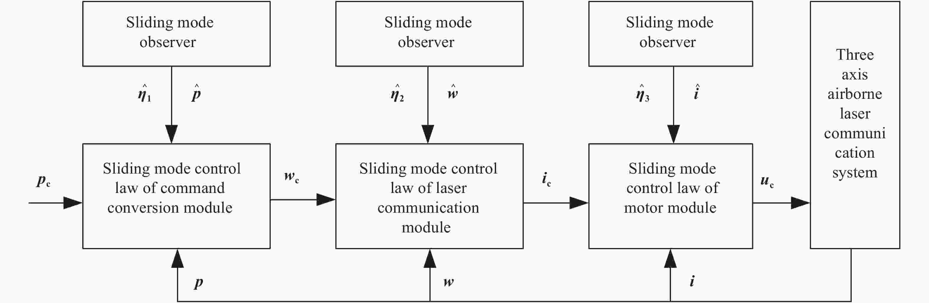
Figure 2. Control system structure
-
针对机载激光通信系统公式(5)设计滑模观测器,来快速、准确地估计复合干扰。指令转换模块的滑模观测器设计为:
式中:
${\hat{\boldsymbol p}}$ 为滑模观测器对${\boldsymbol{p}}$ 的估计值;${{\boldsymbol{p}}_e} = {\hat{\boldsymbol p}} - {\boldsymbol{p}}$ 表示滑模观测器的估计误差;${\tilde{\boldsymbol p}} = {\boldsymbol{p}} - {{\boldsymbol{p}}_c}$ 表示机载激光通信系统对于目标方位的跟踪误差,其中${{\boldsymbol{p}}_c} = {\left[ {\begin{array}{*{20}{c}} {{x_c}}&{{y_c}}&{{ {\textit{z}}_c}} \end{array}} \right]^{\rm{T}}}$ 表示输入的目标方位坐标;${\hat{\boldsymbol \eta }_1}$ 为复合扰动${\boldsymbol{\eta }_1}$ 的估计值,${{\tilde{\boldsymbol \eta }}_1} = {{\hat{\boldsymbol \eta }}_1} - {{\boldsymbol{\eta }}_1}$ 表示估计误差;${{\boldsymbol{k}}_1}$ 和${{\boldsymbol{k}}_2}$ 为待设计的正定矩阵。激光通信模块的滑模观测器设计为:
式中:
${\hat{\boldsymbol w}}$ 为滑模观测器对${\boldsymbol{w}}$ 的估计值;${{\boldsymbol{w}}_e} = {\hat{\boldsymbol w}} - {\boldsymbol{w}}$ 表示滑模观测器的估计误差;${\tilde{\boldsymbol w}} = {\boldsymbol{w}} - {{\boldsymbol{w}}_c}$ 表示机载激光通信系统对于转动角速度指令的跟踪误差,其中${{\boldsymbol{w}}_c} = $ $ {\left[ {\begin{array}{*{20}{c}} {{{\dot \varphi }_c}}&{{{\dot \theta }_c}}&{{{\dot \psi }_c}} \end{array}} \right]^{\rm{T}}}$ 由指令转换模块解算得到的转动角速度指令;${{\hat{\boldsymbol \eta }}_2}$ 为复合扰动${{\boldsymbol{\eta }}_2}$ 的估计值,${{\tilde{\boldsymbol \eta }}_2} = {{\hat{\boldsymbol \eta }}_2} - {{\boldsymbol{\eta }}_2}$ 表示估计误差;${{\boldsymbol{k}}_3}$ 和${{\boldsymbol{k}}_4}$ 为待设计的正定矩阵。电机模块的滑模观测器设计为:
式中:
${\hat{\boldsymbol i}}$ 为滑模观测器对${\boldsymbol{i}}$ 的估计值;${{\boldsymbol{i}}_e} = {\hat{\boldsymbol i}} - {\boldsymbol{i}}$ 表示滑模观测器的估计误差;${\tilde{\boldsymbol i}} = {\boldsymbol{i}} - {{\boldsymbol{i}}_c}$ 电机对于电流指令的跟踪误差,其中${{\boldsymbol{i}}_c}$ 为由激光通信模块解算得到的电流指令;${{\hat{\boldsymbol \eta }}_3}$ 为复合扰动${{\boldsymbol{\eta }}_3}$ 的估计值,${{\tilde{\boldsymbol \eta }}_3} = {{\hat{\boldsymbol \eta }}_3} - {{\boldsymbol{\eta }}_3}$ 表示估计误差;${{\boldsymbol{k}}_5}$ 和${{\boldsymbol{k}}_6}$ 为待设计的正定矩阵。 -
在滑模观测器的基础上,设计了反步滑模控制律,实现对机载激光通信系统的高精度控制。
Step 1:指令转换模块控制律设计
构建如下Lyapunov函数
${{\boldsymbol{V}}_1}$ :对公式(9)求导,并将公式(5)和公式(6)代入,可得:
根据公式(10),可以设计虚拟控制指令为:
式中:k7为待设计的正定矩阵。公式(11)即为激光通信模块的转动角速度指令, 将公式(11)代入公式(10),化简可得:
由Lyapunov稳定性定理可得到,所设计控制指令公式(11)可以确保系统能够稳定跟踪方位信号pc。
Step 2:激光通信模块控制律设计
构建如下Lyapunov函数
${{\boldsymbol{V}}_2}$ :对公式(13)求导,并将公式(5)和公式(7)代入,可得:
根据公式(14),可以设计虚拟控制指令为:
式中:k8为待设计的正定矩阵。公式(15)即为电机的电流指令,将公式(15)代入公式(14),化简可得:
由Lyapunov稳定性定理可以得到,设计的控制指令公式(15)可以确保系统能够稳定跟踪转动角速度指令wc。
Step 3:电机模块控制律设计
构建如下Lyapunov函数
${{\boldsymbol{V}}_3}$ :对公式(13)求导,并将公式(5)和公式(8)代入,可得:
根据公式(18),可设计电机的电压控制指令为:
式中:k8为待设计的正定矩阵。公式(19)即为电机的电流指令,将公式(19)代入公式(18),化简可得:
由Lyapunov稳定性定理可以得到,设计的控制指令公式(19)可确保系统能够稳定跟踪电流指令ic。
综合以上分析可以得到针对机载激光通信系统设计的反步滑模控制律为:
-
定理:针对带有复合干扰的三轴机载激光通信系统公式(5),设计的基于滑模观测器的反步滑模控制律公式(21),能够确保系统稳定。
证明,构建如下Lyapunov函数
$W$ :对上式求导并将公式(12)、(16)、(20)代入,得:
由Lyapunov稳定性定理可得定理成立,即设计的基于滑模观测器的反步滑模控制律公式(21)能够确保三轴机载激光通信系统稳定。
-
为了验证设计的反步滑模控制方法对机载激光通信系统的控制效果,采用提出的方法与参考文献[16]的分数阶PID控制方法进行对比实验。整个仿真过程持续10 s,机载激光通信系统的初始状态均为0。设置仿真环境参数如下:
通信对象的坐标指令:
复合扰动:
控制律参数如表1所示。
Parameters Value Parameters Value k1 diag{3,5,6} k2 diag{2,1,3} k3 diag{4,3,5} k4 diag{5,7,2} k5 diag{8,6,3} k6 diag{2,5,7} k7 diag{9,2,5} k8 diag{4,2,7} k9 diag{4,2,6} -- -- Table 1. Control law parameters
-
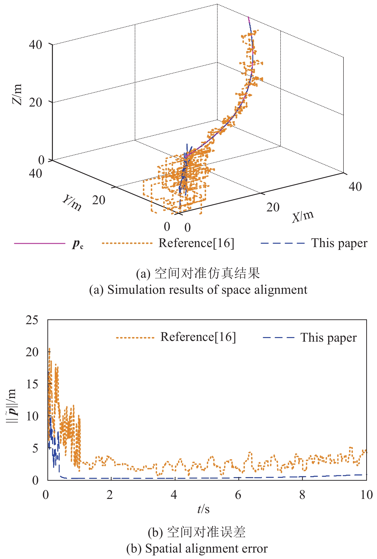
由于激光通信质量取决于视轴能否对准通信对象方位坐标,实验将机载激光通信系统视轴与通信坐标对象的对准情况进行仿真,得到的空间对准结果如图3所示。

Figure 3. Simulation results of space alignment
由空间对准仿真结果可看出:在参考文献[16]控制方法的作用下,机载激光通信系统能够在1 s后大致跟踪通信对象的坐标变化趋势,但是会在指令pc附近剧烈振荡,最大振荡误差为5 m;而在文中反步滑模控制方法的作用下,机载激光通信系统能够在0.4 s内准确跟踪通信对象的坐标指令pc,最大误差仅为0.3 m。
为了进一步突出文中方法的优越性,给出x、y和z坐标对准结果如图4~6所示。

Figure 4. Coordinate alignment simulation of x
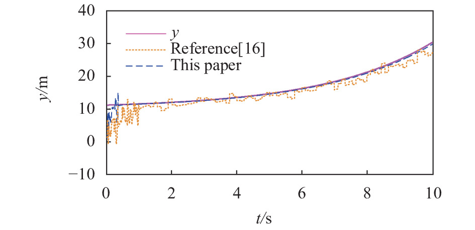
Figure 5. Coordinate alignment simulation of y

Figure 6. Coordinate alignment simulation of z
由仿真结果图4~图6中的x、y、z坐标对准可看出:在参考文献[16]控制方法的作用下,机载激光通信系统能够在1 s后大致跟踪通信对象的坐标变化趋势,但会在指令附近剧烈振荡,最大振荡误差分别为4 m、4 m和4.5 m;而在文中反步滑模控制方法的作用下,机载激光通信系统能够在0.4 s内准确跟踪通信对象的坐标指令,最大误差仅为0.3 m。
-
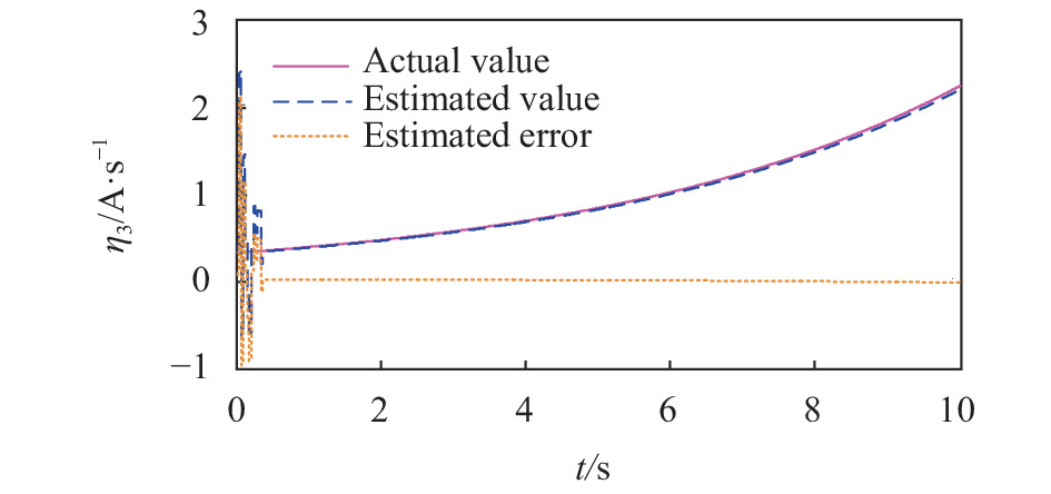
为了进一步验证文中所设计的滑模观测器的有效性,给出扰动估计结果如图7~9所示。
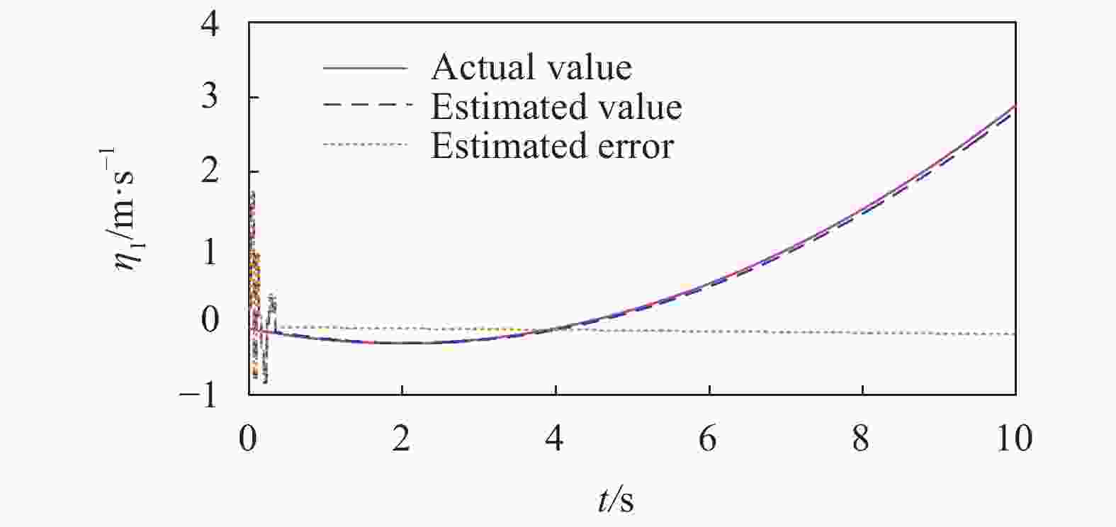
Figure 7. Estimated results of
${\eta _1}$ 
Figure 8. Estimated results of
${\eta _2}$ 
Figure 9. Estimated results of
${\eta _3}$ 由仿真图可看出:设计的滑模观测器能够在0.3 s内准确估计扰动值,最大估计误差分别仅为0.1 m/s、0.06 (°)/s2和0.07 A/s,估计速度和估计精度均较高。
-
针对复合扰动下机载激光通信系统的视轴对准问题,采用滑模观测器设计了反步滑模控制方法,通过Matlab仿真实验验证了设计的反步滑模控制方法的响应速度较快,能够确保机载激光通信系统在0.4 s内稳定跟踪指令信号,且控制精度也较高,最大空间对准误差仅为0.3 m,实现了对激光通信系统视轴的高精度控制,设计的滑模观测器能够快速、准确地估计出扰动值,响应速度仅为0.3 s,最大估计误差分别仅为0.1 m/s、0.06 (°)/s2和0.07 A/s,大幅提升了视轴的对准精度,从而能够有效改善激光通信的质量。
Precision control of airborne laser communication optical axis using sliding mode observer
doi: 10.3788/IRLA20210460
- Received Date: 2021-12-07
- Rev Recd Date: 2022-01-20
- Publish Date: 2022-04-07
Fund Project:
National Natural Science Foundation of China (61603344);Foundation for Young Key Teachers of Colleges and Universities in Henan Province(2017GGJS227)
-
Key words:
- airborne laser communication system /
- optical axis alignment /
- disturbance /
- sliding mode observer /
- back-stepping sliding mode control
Abstract: To improve the optical axis alignment accuracy of airborne laser communication system under the disturbance of body vibration and mechanical friction, a back-stepping sliding mode control method based on sliding mode observer was proposed. Firstly, the mathematical model of the airborne laser communication system was established, and then the disturbance value was estimated by the designed sliding mode observer. At the same time, the back-stepping sliding mode control law was gradually designed for the command conversion module, laser communication module and motor module, which realized the high-precision control for the optical axis of the airborne laser communication system. The experimental results show that the proposed method has better rapidity and accuracy than the fractional PID control method, the response time is only 0.4 s, the maximum space alignment error is only 0.3 m, the designed sliding mode observer can estimate the disturbance value quickly and accurately, the response time is only 0.3 s, and the maximum estimation error is only 0.1 m/s, 0.06 (°)/s2 and 0.07 A/s, which greatly improves the alignment accuracy of the optical axis in the airborne laser communication system.


 DownLoad: