


-
近年来,激光雷达测风系统不断快速发展并被广泛应用于航空安全、大气科学、风力发电、气象预报等重要领域[1-2]。作为一种新型的风速测量仪器,激光雷达测风系统在实时风速测量领域具有一定的需求量,同时测风系统对回波信号数据量、传输速率要求也越来越高[3]。对回波信号进行高速采集与处理是激光雷达测风系统的重要环节。为利用多普勒频谱进行风速反演,同时提高测风系统的信噪比,需要对回波信号采取FFT运算,并对运算结果进行多次累加平均。目前,市面上对回波信号的FFT运算与频谱数据的累加平均一般采用DSP或者ASIC(专用集成电路),其中前者采用指令集进行数据运算,测风实时性稍有欠缺;而后者成本高,欠缺可维护性与可配置性[4-5]。中国电子科技集团李河均等人采用商业数据采集卡和LABVIEW软件设计了激光测风雷达信号处理系统,通过验证该信号处理系统能够实现0.8 m/s的速度测量精度[6];如今市面上多数激光雷达测风系统风速精度为0.1 m/s,例如北京波恩仪器仪表测控技术有限公司BN-WDR、南京牧雷激光科技有限公司Molas B300产品等。
针对激光雷达测风系统在数据传输速度、处理精度以及实时性等方面需求,该研究在连续相干激光雷达测风原理基础上,利用光学器件以及自主设计的基于FPGA的高速信号采集处理模块、数据传输模块和上位机应用程序,搭建了一套完整的连续相干激光雷达测风系统。实现对激光雷达回波信号的实时采集处理与显示分析。文中将着重介绍基于FPGA的高速信号采集处理模块的原理及设计过程,该模块能够实现回波数据的实时运算,保证了激光雷达测风系统的实时性和准确性,具有较高的工程应用推广价值。
-
激光雷达测风系统原理如图1所示,由连续光纤激光器、光纤放大器、环形器、望远镜、可调光衰减器、保偏光纤耦合/分束器、平衡探测器、ADC和FPGA组成的信号采集处理模块、上位机等组成。
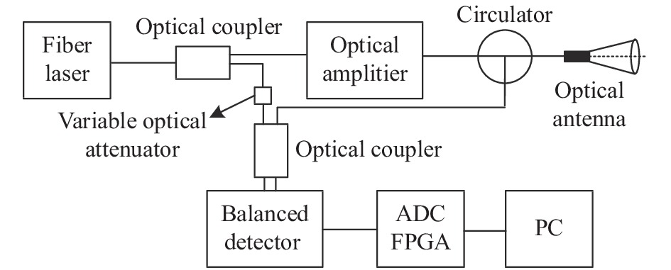
Figure 1. Schematic diagram of lidar wind measurement system
利用连续光纤激光器产生波长为1 550 nm的连续激光,经保偏分束器分成两路:一路光通过可调光衰减器作为本振光在保偏光纤耦合/分束器实现相干处理;另一路探测光通过光纤放大器进行功率放大,进入到光纤环形器,经过同轴望远镜发射频率为
${f_a}$ 的光信号到大气中。该光信号通过大气中气溶胶颗粒散射后返回频率为${f_b}$ 的回波光信号,该回波光信号被聚焦透镜接收耦合后通过光纤与本振光进行外差相干混频,得出多普勒频移$\Delta f$ ,此时风速$v$ 与多普勒频移$\Delta f$ 关系为[7-8]:式中:
$\lambda $ 为1 550 nm。相干后的光信号在平衡探测器上转换为电信号,经过信号采集处理模块将模拟信号转换为数字信号,再通过FPGA进行FFT运算以及频谱数据累加平均,通过上位机软件反演出风速。为了得到多普勒频移$\Delta f$ ,基于以上原理搭建一套激光雷达测风系统,主要器件参数标定如表1所示。Name Parameters Value Fiber laser Wavelength/nm 1 550 Output power/mW 10 Line width/kHz 3 Balanced detector Responsivity/A·W−1 0.95 3 dB bandwidth/MHz 100 Telescope Focus distance/m 50 ADC Resolution/bit 14 Sampling rate/MHz 100 Table 1. Parameter calibration of main components of lidar wind measurement system
利用上述设定参数器件搭建的激光雷达测风系统,将望远镜聚焦距离固定在50 m左右,进行实际风速测量与实验数据分析,得出测风系统的性能指标。
-
根据激光雷达回波信号特点,研制了高速信号采集处理模块,同时设计数据传输模块将采集处理后的数据实时传输到上位机进行分析、处理及显示,其框图如图2所示。

Figure 2. Block diagram of signal acquisition and processing and data transmission module
为了得到回波信号的有效频谱,信号采集处理模块采用“高速ADC+FPGA”架构,其中高速ADC采用ADI公司AD9268芯片,其最大采样速率为125MSPS,分辨率为16位。FPGA采用Intel公司高性能、低功耗Cyclone IV系列芯片EP4CE115作为核心控制器,利用控制逻辑及相关运算实现对回波信号的实时采集、FFT运算、累加平均及数据传输。
-
数据传输模块通过SPI总线与信号采集处理模块进行通信,同时利用TCP/IP协议与上位机通信。该模块采用Intel公司Cyclone V SOC系列芯片5CSEBA6U作为核心控制器,该芯片包含FPGA部分与HPS(Hard Processing System)部分,其中FPGA部分实现SPI传输控制逻辑,实时读取信号采集处理模块的数据;HPS部分拥有双核Cortex-A9处理器与相关外设接口,其运行频率高达925 MHz,利用芯片内部高速AXI(Advanced eXtensible Interface)总线,与FPGA部分可实现最高128位宽数据通信。当AXI总线运行200 MHz时,数据位宽为128位,FPGA和HPS的通信速率:128×200÷8=3 200 MB/s,大大提高了二者之间数据传输效率,解决了大数据量传输瓶颈。
此外,由于Qt框架支持跨平台C++图形用户界面开发,具有良好的封装机制,可重用性好[9],该研究基于此框架开发了一套回波信号频谱分析显示应用程序,并实时计算出风速参数。
-
实际风速测量过程中,提取到有效的多普勒频谱信息对实现风速反演有着重要意义,目前FFT算法的实现有软件与硬件两种实现方式[10]。针对激光雷达回波信号实时性强的特点,软件方式实现存在运算速度慢、延时长等问题,对数据的处理欠缺实时性,因此研究硬件实现FFT对激光雷达测风系统有着重要意义。该研究使用了块浮点结构,将采集到的回波数据在FPGA上进行实时FFT流模式运算。
FFT是离散傅里叶变换(以下简称DFT)的快速算法,长度为
$N$ 的DFT单位圆上计算均匀分布的$N$ 个点$W_N^{nk}{\rm{ = }}{{\rm{e}}^{{{ - j2\pi nk} / N}}}$ 组成的时域离散序列$x(n)$ 的傅里叶变换[11]:Cooley-Tukey(库利-图基)FFT算法是变换长度
$N$ 是$r$ 基幂的形式,即$N = {r^x}$ ,该算法称为基$r$ 算法。采用基-4 FFT可以降低运算对FPGA资源的占用量,提高FPGA对回波数据运算的效率,提高频谱数据运算精度,其基本结构是每一级运算由${N / 4}$ 个蝶形运算构成,将序列$x(n)$ 分成4个${N / 4}$ 点的序列,原理如下:令:
得:
将
$x(n)$ 代入DFT表达式中,则有:把
$X(k)$ 按频率抽取,得: -
根据上述原理,该研究采用时序控制逻辑结合封装完成的FFT IP核,在100 MHz全局时钟下对1 024点回波数据进行FFT运算,仿真结果表明一帧FFT运算时间约为100 μs,相比DSP等软件编程方式处理频谱数据拥有更好的实时性。此设计在提高数据测量精准度的同时也缩短了开发周期。对FFT IP 核进行状态机控制逻辑编写得到的时序仿真如图3所示。
其中sink_sop与sink_eop表示输入一帧数据的开始与结束;sink_real与sink_imag表示输入数据的实部与虚部;source_sop与source_eop表示一帧FFT计算结果输出的开始与结束;source_real与source_imag表示计算输出数据的实部与虚部;sink_ready与source_ready表示FFT引擎可以接收数据与发送数据。sink_valid信号拉高时表示输入端口数据有效,source_exp表示FFT计算输出数据的指数。
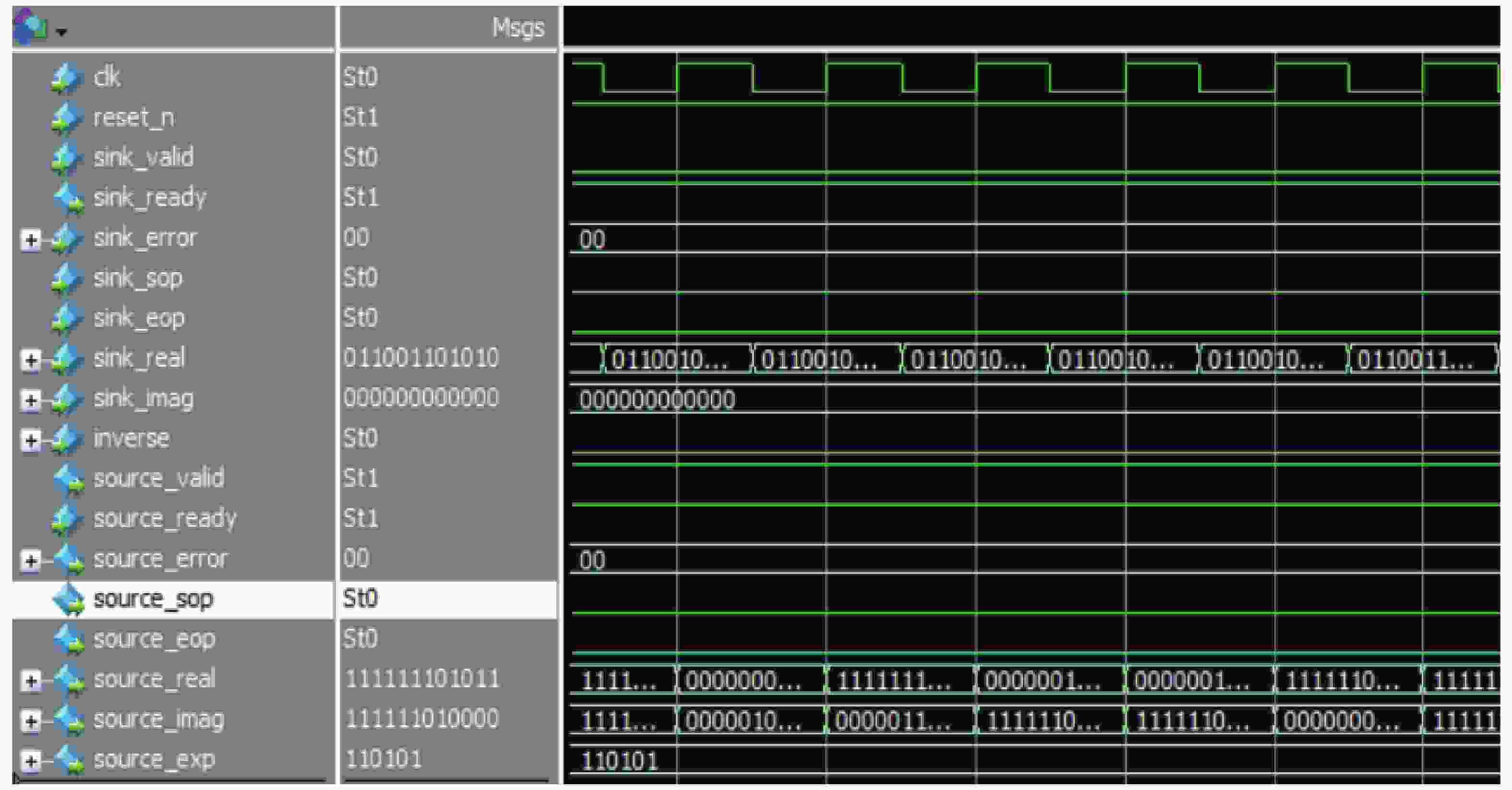
Figure 3. Timing simulation diagram under stream mode and block floating-point structure
-
激光雷达回波信号频谱复杂、背景噪声复杂,为提高系统测风的精准度,保证测风过程的实时性的同时有效降低背景噪声对测风精度的影响,需要在信号采集处理模块内,利用10 kHz的内部触发信号对回波信号进行1 024个点的采集处理。整个算法设计在状态机逻辑控制下完成,将FFT运算后的数据进行对应点累加,累加后数据移位至存储器中,最终累加平均结果通过SPI总线发送给数据传输模块,算法架构如图4所示。
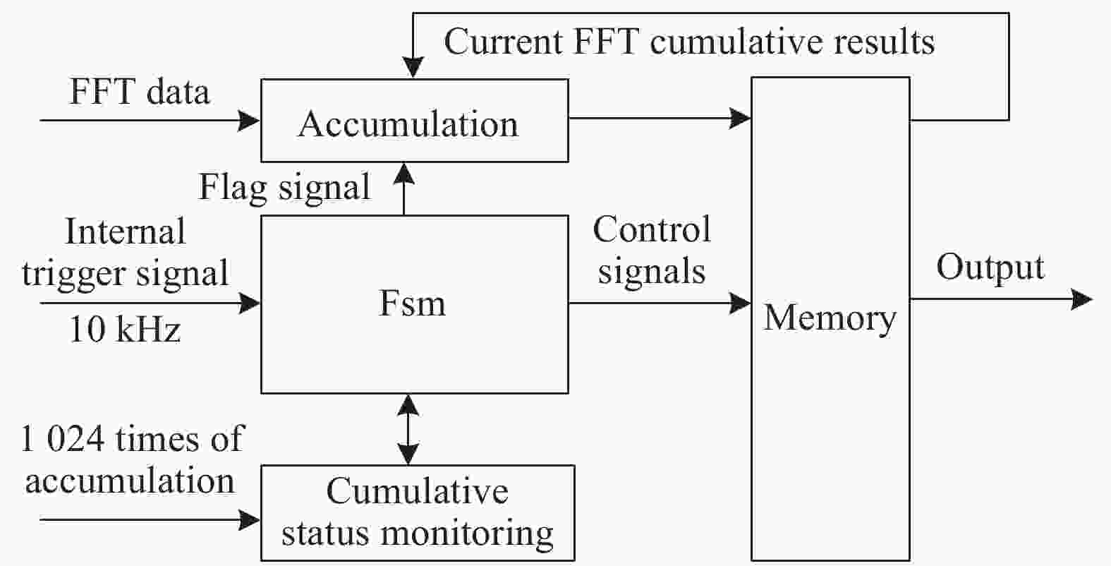
Figure 4. Architecture diagram of cumulative average algorithm
-
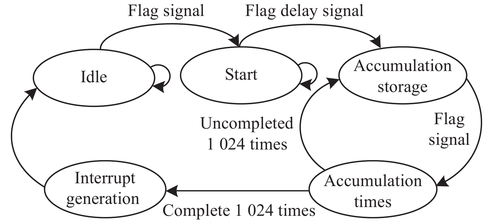
FPGA中FFT累加平均运算由并行累加存储单元、累加次数判断单元、存储器等模块以及相关标志信号协同工作完成。FFT的计算结果输出标志作为状态机的驱动,标志信号确保每次FFT计算结果的对应点依次累加,保证了数据准确性,图5是1 024次累加状态转移图,其运行频率为100 MHz。
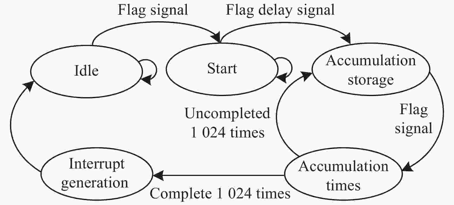
Figure 5. Cumulative state transition diagram
在空闲状态下,初始化并行累加存储单元与累加计数器;当检测到标志信号时,跳转到开始累加状态;等待延迟标志信号,将FFT算出的第一组数据写入存储器模块中,状态跳转到累加存储单元。状态机检测到第二次标志信号时,开启并行累加器使能,开始将第一组数据与第二组数据进行对应点累加存储,同时将新的累加结果写入存储器模块;在完成一次新数据累加存储后,跳转到累加判断状态,进行当前累加次数与1 024次进行比较,如果未到达则跳回累加存储状态继续累加存储;如果到达则跳转到累加完成状态,同时给出中断信号。控制逻辑将累加数据右移10位得到1 024次累加平均数据,通过SPI总线将该累加平均数据发送给数据传输模块。
-
DSP在20 MHz主频下完成一次1 024点采集任务结束后,DSP在0.2 ms内(采集1 024个数据的时间:1 024×10 ns≈0.01 ms)将1024个数据读入DSP存储器暂存[12],等1 024次采集结束后,需要的时间约为0.2 ms×1 024≈205 ms。将DSP主频设置为100 MHz,完成1 024次采集需要41 ms左右,并且在1 024次采集任务完成之后DSP还需要进行对应点的累加平均工作,此过程又会消耗DSP大量存储空间与时间,将导致后续风速反演速度变慢,导致测风系统实时性变差。另外,当采集数据点数增加时、累加平均次数增多时,完成单次数据点采集时就花费DSP更多的时间与存储空间,数据读取的时间也会更长,这就会使测风系统实时性较差、并且也欠缺后期的可配置性。
相较于上述方案,该研究利用FPGA设计累加平均算法,当采样频率
${f_S}$ =100 MHz,FFT长度P=1 024点,N=1 024次时,根据以下公式[13]:得到累加平均数据的采样时间T约为10 ms:两者数据对比表明,该研究所设计的硬件实现累加平均算法,能大幅度提高频谱数据运算速度,提高系统的时间分辨率与测风精度。
-
为了对连续相干激光雷达测风系统的回波信号进行采集处理与显示,同时验证采集处理模块的性能指标,在实验室搭建激光雷达侧风系统实验平台。实验平台如图6所示,该平台有以下模块组成,其中①~⑧分别为连续激光器、光纤放大器、可调光衰减器、望远镜、平衡探测器、采集处理模块、数据传输模块和上位机。
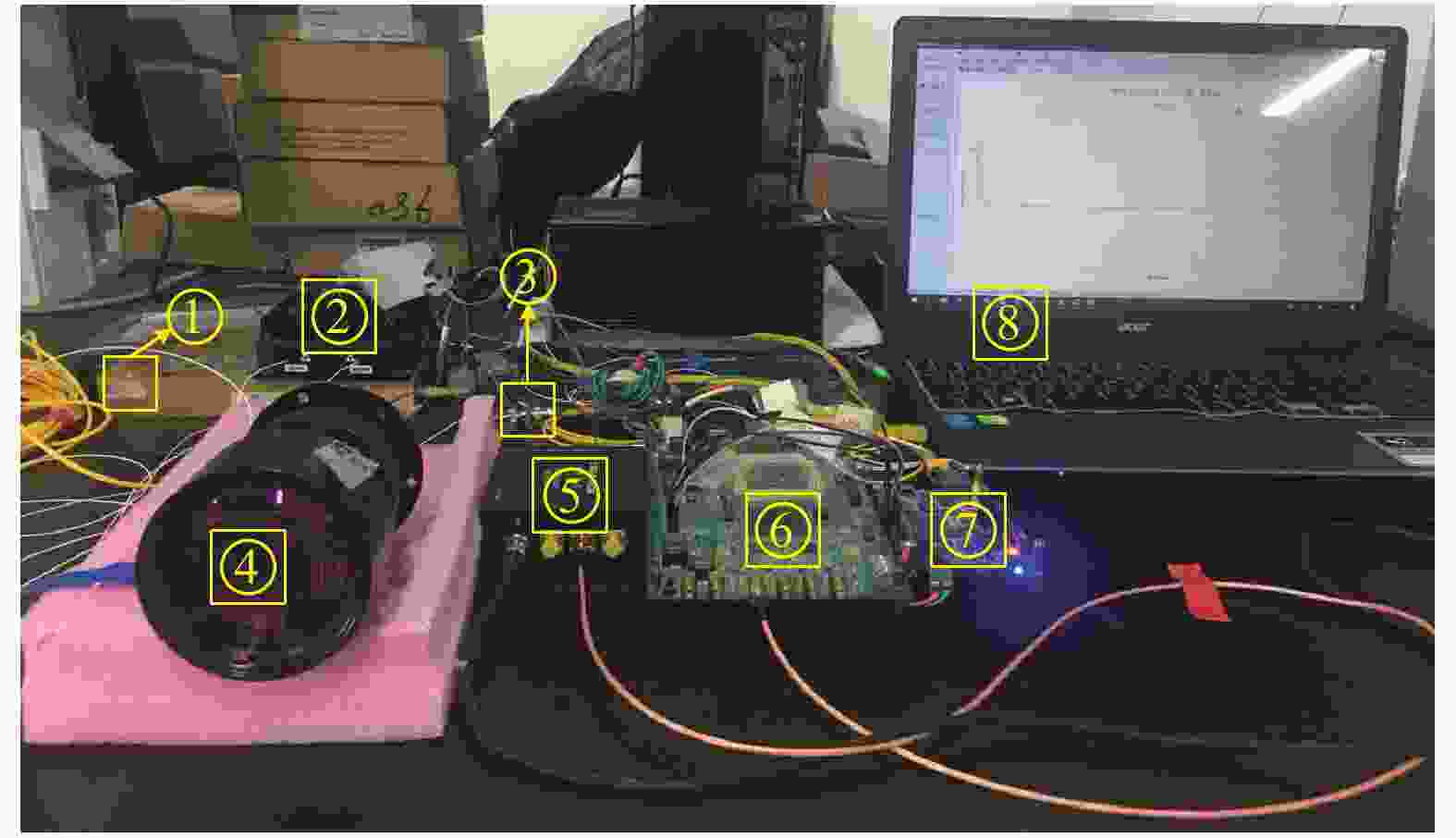
Figure 6. Lidar wind measurement system
①~⑤以及光纤组成了连续相干激光雷达部分,将设计的⑥~⑧接入到连续相干激光雷达部分,组成完整的激光雷达测风系统。相干后的光信号在⑤上转换为电信号,通过⑥进行实时采集、FFT计算多普勒频移、并对频谱数据进行累加平均运算;将处理后的数据通过SPI总线传输到⑦上,最后通过网线传输到⑧实时监控频谱数据,并进行风速反演。
-
搭建的该套激光雷达测风系统能够实现的性能指标如表2所示。
Parameter Value Detection range/m 10-100 Wind speed measurement range/m·s−1 0-38 Spectral resolution/kHz 97.66 Wind speed measurement accuracy/cm·s−1 7.57 Wind speed data refresh frequency/Hz 8 Table 2. Performance indicators of wind measurement system
由于光的衍射,连续激光超过一定距离无法聚焦,测量距离经常在几十到数百米之间[14],ADC的数据采集速率为100 MHz,根据奈奎斯特采样定理,超过50 MHz后的多普勒频谱数据将会失真,所以该系统最大测量风速约为38 m/s;其中频谱分辨率由数据采样频率除以采样点数得到,即:100 MHz/1 024≈97.66 kHz,根据频谱分辨率得出系统的测量风速的精度为7.57 cm/s,经过系统联调测试,风速数据刷新频率为8 Hz。
-
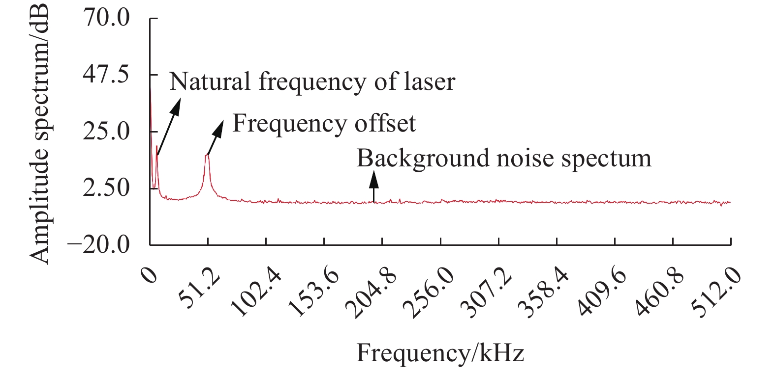
为了验证累加平均算法对激光雷达回波信号背景噪声的滤波效果,利用采集处理模块分别实现对回波信号频谱单次测量与1 024次累加平均测量。图7为单次回波信号频谱,X轴表示信号的频率,其分辨率为0.1 MHz;Y轴表示幅值谱,采用对数坐标,单位为dB。其背景噪声频谱幅度波动范围为−10~10 dB。

Figure 7. Frequency spectrum of single echo signal
图8是经过1 024次累计平均之后的频谱图,由图可知,其背景噪声幅值谱波动范围为−1~1 dB。通过两图对比可知,激光雷达回波信号经过单次FFT变换时,其背景噪声频谱幅度波动大,通过1 024次累加平均后,可明显消除背景噪声的频谱干扰。图中第一个峰对应频率是连续激光器固有频率,第二个峰是有风时测得的频率偏移量,频率为5 MHz,此时将
$\Delta f{\rm{ = }}5\; {\rm{MHz}}$ ,$\lambda {\rm{ = }}1\;550 \;{\rm{nm}}$ 代入公式(1)得出风速为3.88 m/s。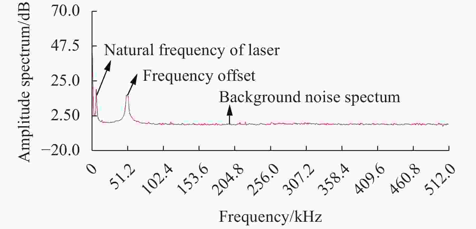
Figure 8. Frequency spectrum of 1 024 cumulative average echo
-
为了验证所设计的模块能否满足实时测风需求,需要考虑模块FPGA资源利用率的大小,资源利用率决定了FPGA并行处理激光雷达回波数据的效率。文中通过优化时序控制逻辑与算法整体架构,大幅减小了FPGA资源利用率,提高了回波数据运算的效率,表3展示了两模块FPGA的资源利用率,由表可知,设计的模块资源利用率小,并行运算回波数据效率高,满足实时测风需求,并在实际测风中得到了很好的验证。
Device FPGA resources Used/Total Rate Cyclone IV Logic elements 5 978/114 480 5% Memory bits 411 086/3 981 312 10% Cyclone V Multiplier elements 40/532 8% Logic utilization 3 671/41 910 9% Memory bits 19 200/5 662 720 <1% Table 3. Resource occupancy rate of FPGA
-
针对连续相干激光雷达测风系统需求,研制了基于FPGA的高速信号采集处理模块,利用该模块实现了对激光雷达回波信号进行流模式、块浮点型1 024点的实时FFT运算,实现了1 024次频谱数据累加平均;同时该累加平均数据通过SPI总线传输至数据传输模块,再经网络发送至上位机,并利用自主开发的Qt应用程序进行风速实时的显示与分析。
通过搭建连续相干激光雷达测风系统对该信号采集处理模块进行系统联调,测试结果表明:设计基于FPGA的高速信号实时采集处理模块能够得到有效的激光雷达回波信号多普勒频谱信息,该设计相比于DSP方案,将1 024次累加平均时间由41 ms以上降至10 ms左右,同时将风速测量精度提升至7.57 cm/s,该系统能有效降低激光雷达回波信号背景噪声的频谱干扰,将回波信号的频谱分辨率提升至97.66 kHz,同时利用SOC架构设计的数据传输模块克服了FPGA与ARM之间的数据通信瓶颈,该模块资源利用率低,并行运算数据效率高,满足实时测风需求,优化了风场对风速测量精度的要求,具有较高的工程应用价值。
Research on signal acquisition and processing of lidar wind measurement system
doi: 10.3788/IRLA20210467
- Received Date: 2021-05-10
- Rev Recd Date: 2021-06-20
- Publish Date: 2021-11-02
-
Key words:
- lidar /
- high-speed signal acquisition and processing /
- FPGA /
- FFT
Abstract: In order to meet the requirements of wind speed measurement in wind field, a high-speed signal acquisition and processing module of lidar wind measurement system based on FPGA has been developed, which was responsible for lidar echo signal acquisition, Fast Fourier Transform (FFT) and spectrum data accumulation and averaging operation. The collected 1 024 point echo data was calculated by flow mode and block floating-point structure FFT to obtain single spectrum data and 1 024 cumulative average spectrum data respectively, and the data transmission module was reliably transmitted to the host computer for display and analysis. By building a continuous coherent lidar wind measurement system with the working wavelength of 1 550 nm, the index of the signal acquisition and processing module was tested and the cumulative average filtering algorithm was verified. The experiment results show that the acquisition and processing module can meet the real-time acquisition and processing of echo signal under the 100 MHz clock, and the spectrum resolution reaches 97.66 kHz, and the accuracy of wind speed measurement is improved to 7.57 cm/s.


 DownLoad: