


HTML
-
非视域成像是近年来在军事侦察、安防反恐、灾难救援等领域对隐藏目标探测的迫切需求下产生的一种特殊成像技术。非视域成像的概念是指当目标被遮挡而无法对其进行直接成像时,通过采集周围场景中和目标相关的各种信号,对目标进行计算重构的方法。在过去的十多年中,出现了多种非视域成像的手段,包括借助于激光脉冲飞行时间测量方法[1-2]、激光散斑相关法[3]、被动半影测量法[4]、热成像法[5-6]、声波测量法[7]、多普勒雷达成像法[8]、稳态成像法[9]等。激光脉冲飞行时间测量方法采用激光窄脉冲进行主动照明,光脉冲经历场景到目标再到场景共三次漫反射才能回到探测器上,通过对回波信号的时空采样,可计算重构出目标的三维形状,这种方法能够获取到大尺度目标的三维信息。由于该方法的成像构型和工作方式与传统激光雷达非常接近,因此文中将其作为一种功能拓展的激光雷达新体制进行详细综述。近年来随着无人驾驶的蓬勃发展,对车载激光雷达的性能和功能都提出了强烈的需求,这种激光雷达新体制有助于视线被遮挡情况下对周围车辆、行人等物体的提前预判,极大提高了无人驾驶的安全系数,因而受到更为广泛的关注。
-
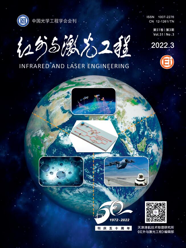
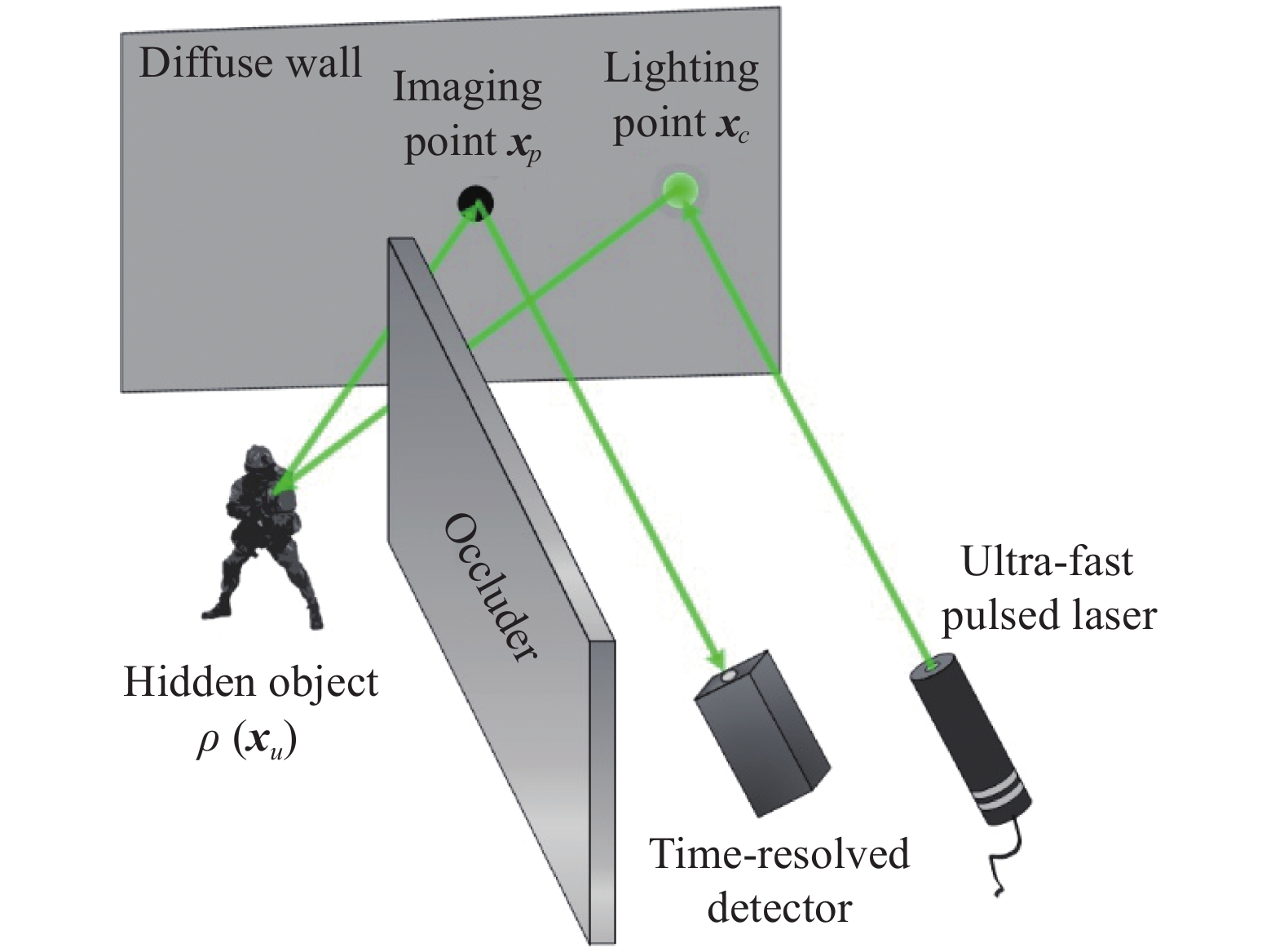
为了更好地综述非视域三维成像激光雷达技术的研究进展,先简要介绍该成像体制的基本原理。目前非视域成像激光雷达的基本成像构型如图1所示。由于遮挡屏的遮挡,目标处于成像系统的视场范围外,用普通的探测方式无法获取目标的信息。
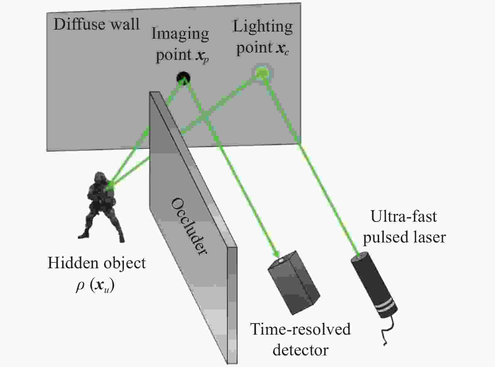
Figure 1. Basic configuration of the non-line-of-sight imaging lidar
非视域三维成像激光雷达的基本原理是利用瞬态脉冲光的多路径散射回波来对非视域目标进行成像。首先分析脉冲光信号的正向传输过程,可将信号从发射到接收分为四个阶段。第一阶段为窄脉冲激光器出射激光在中介面上形成照明点
${{\boldsymbol{x}}_c}$ ,第二阶段为照明点处的一次散射光照在目标上的任意一点${{\boldsymbol{x}}_u}$ ,第三阶段为光经目标二次散射回到中介面上的${{\boldsymbol{x}}_p}$ ,第四阶段为光经中介面的三次散射后被探测器接收。目标的信息就蕴含在三次散射信号中。考虑到整个目标上各点都会形成上述的正向传输过程,那么探测器上接收到的信号可以通过下式进行计算:式中:
$\; \rho ({{\boldsymbol{x}}_u})$ 为目标反射率的空间分布;$H({{\boldsymbol{x}}_p},{{\boldsymbol{x}}_c},t,{{\boldsymbol{x}}_u})$ 为目标域到测量域的点脉冲响应函数,通过扫描方式改变${{\boldsymbol{x}}_p}$ 和${{\boldsymbol{x}}_c}$ ,使接收信号$P({{\boldsymbol{x}}_p},{{\boldsymbol{x}}_c},t)$ 成为测量域$({{\boldsymbol{x}}_p},{{\boldsymbol{x}}_c},t)$ 中的分布函数。非视域三维成像的基本原理就是先对$H({{\boldsymbol{x}}_p},{{\boldsymbol{x}}_c},t,{{\boldsymbol{x}}_u})$ 进行精确建模,然后测量$P({{\boldsymbol{x}}_p},{{\boldsymbol{x}}_c},t)$ ,最终求解目标$\; \hat \rho ({{\boldsymbol{x}}_u})$ 。这是典型的求解积分方程的反问题。因此,非视域三维成像激光雷达有两个重要的关键技术,一是对瞬态光场进行时空采样的硬件系统,二是利用理论模型和采样数据进行图像还原的重构算法。 -
非视域成像技术最早源于对激光成像雷达功能拓展的研究。从2009年概念的提出,历经2012年的重大突破,到目前已进入全面开花的态势。世界上多家研究机构都进行了非视域成像的探索工作,国外包括美国的麻省理工学院、斯坦福大学、威斯康辛大学、康奈尔大学、瑞典的国防研究中心、法国的圣法德路易斯研究院、英国的赫瑞瓦特大学等单位。国内包括北京理工大学、中国科学技术大学、哈尔滨工业大学、中国科学院西安光学精密机械研究所、海军工程大学等单位。此外,非视域成像技术同样也引起美国的DARPA、英国国家量子技术中心这样的大型研究机构的关注,并制定了相应的研究计划予以支持。非视域成像已经逐渐发展成为激光雷达领域的一个独立研究分支。下面笔者将按照成像系统、成像算法两个方面分别进行研究现状分析。
(1)非视域成像系统的研究进展
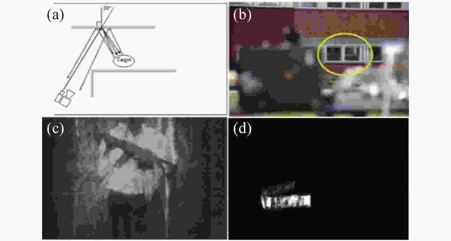
2009年,瑞典国防研究中心和德国光子学及模式识别研究中心首次提出了非视域成像的概念并且进行了实验验证[10]。实验中采用1.5 μm的脉冲激光器作为源,单脉冲能量可达20 mJ,探测器为选通型短波红外相机。该设备能够成功从玻璃窗的反射信号中获取到距窗20 m远的人和30 m远的车牌,后续还借助水面、车体等类镜面体来探测隐藏物体。实验结果很大程度上依赖散射体的类镜面性质[11],见图2。
2012年,北京理工大学的许凯达等人搭建了基于532 nm激光器和ICCD 探测器的距离选通成像系统,激光脉冲和选通门宽均为20 ns。以窗户玻璃和墙面瓷砖作为中介反射面,分别获得了50 m和20 m处目标的非视域图像。实验结果表明:非视域成像的效果与中介反射面的反射特性有关,许多具有一定镜面反射特性的建筑材料均可作为中介反射面而用于非视域成像[12]。他们也从理论上构建了非视域成像对比度模型并进行了仿真,仿真结果表明,对于大多数实用的中介反射面,只有采用激光距离选通成像模式才能实现非视域成像,而且中介面距离目标越近,系统探测识别目标的难度就越大[13-14],见图3。

Figure 3. Experimental results of non-line-of-sight imaging with different mirror surfaces[12]. (a)-(d) Position map of the detector, light source, target and the intermediate reflective surface and target respectively; (e)-(h) Experimental results of mirrors with different materials
2015年,海军工程大学的韩宏伟等人基于窄脉冲激光器和ICCD搭建了非视域主动成像实验系统。激光器工作波长为532 nm,最大重复频率10 Hz,单脉冲能量80 mJ,脉宽为10 ns。ICCD的最小选通门宽1.5 ns。以玻璃作为中介反射面,以黑白条纹靶板作为目标,对目标和周围环境处于不同光照情形时系统的非视域成像效果进行测试。结果表明,基于距离选通的非视域成像技术是一种能够在不同光照条件下实现对视觉盲区进行有效观察的成像技术[15],见图4。图4(b1)为C 处开灯,非距离选通成像,图4(b2)为A 处开灯,非距离选通成像,图4(b3)为B 处开灯,非距离选通成像,图4(b4)为距离选通成像, 延迟时间为 0 ns,图4(b5)为距离选通成像,延迟时间为20 ns。
Figure 4. Experimental results of non-line-of-sight imaging with glass under different background lights[15]. (a) Schematic diagram of the experimental scene; (b1)-(b5) Experimental results under different conditions
以上几种成像方案都是基于中介面的类镜面反射特性的,虽然技术可行性较强,但是对类镜面中介面的这种先决条件大大限制了非视域成像的应用范围。
2012年,美国麻省理工学院的Andreas Velten等人首次提出了一种真正意义上的非视域三维成像方法[1-2](图5)。他们利用了50 fs脉宽的超快激光器、摆镜、具有2 ps时间分辨率的条纹相机来构建成像系统。实验中利用摆镜对激光发射点进行扫描,在60个不同空间照明点的位置下用条纹相机采集了目标散射光场在中介面上的时间波形。然后通过计算获得了非视域目标的三维图像。实验发现在垂直于中介面的方向上(纵向)可以获得较高的分辨率,达到0.4 mm,而在平行于中介面的方向上(横向)分辨率不理想,仅为
$5 \sim 10\;{\text{mm}}$ 。该方法的提出具有非常重要的意义,实验中首次采用标准朗伯体作为散射目标和场景,验证了利用普通材料的散射光信息也能还原隐藏目标。
2013年,法国圣法德路易斯研究院的Martin Laurenzis[16-17]等人研究利用高分辨率的ICCD相机实现激光非视域三维成像。他们的系统所采用的激光器脉宽为2 ns,ICCD相机的横向分辨率1360×1024,选通门宽为2 ns。实验中,课题组采用ICCD面阵进行空间采样、步进选通门进行时间采样的方式采集信号,目标是一块方形平面白板。他们尝试了点照明和面照明两种方式。由于受到选通门宽的限制,时间分辨率无法做到很高,非视域目标的重构结果无法令人满意,但是该研究证明了阵列探测器是可以实现非视域成像的,见图6。
Figure 6. Experimental results of non-line-of-sight imaging using ICCD[17]. (a)-(c) Results of point lighting experiment; (d)-(f) Results of surface lighting, from left to right are top view, side view, 3D panorama
2014年期间,加拿大英属哥伦比亚大学和德国波恩大学的Felix Heide等人研究采用普通的调制光源和光子混频器构建的实验系统进行非视域成像[18-20],光源包括6个250 mW的激光器,总功率达到1.5 W,波长为650 nm。根据散射材料的不同,实验中可以获得分辨率从几厘米到十几厘米的三维目标像。但由于光源功率及探测器灵敏度的限制,信号的采集时间需从几分钟到几百分钟,见图7。

Figure 7. Experimental results of non-line-of-sight imaging using PMD[18]. (a) Scene; (b) System; (c) Lighting source; (d) Target; (e) Intensity image; (f) Depth image
2015年,意大利米兰理工大学和美国威斯康辛大学的Mauro Buttafava等人提出利用选通型单光子探测器(SPAD)加扫描摆镜的非视域成像系统[21]。实验中所采用的光源是波长为515 nm的脉冲激光器,平均功率为50 mW,脉宽为250 fs,通过摆镜对场景进行185个点的扫描。利用单像素SPAD在各扫描点下对信号的时间波形进行光子计数采样,SPAD探测器的时间分辨率达到30 ps,总采样时间为5~32 min,利用获取到的波形数据进行图像重构,重建分辨率可达到几厘米的量级。该实验验证了在低照明功率、大尺度场景的条件下,利用SPAD的光子计数手段可以进行非视域成像,之后该成像系统就成为非视域成像研究的主流构型,见图8。

Figure 8. Experimental results of non-line-of-sight imaging using single pixel of SPAD [21]. (a) Experimental setup; (b) Reconstructed image
2015年,圣法德路易斯研究院的Martin Laurenzis等人就利用32×32的InGaAs SPAD阵列作为接收器构建了非视域探测系统[22],实验中采用的光源为500 ps的光纤激光器,照明方式为固定点照明,探测器阵列的时间分辨率为250 ps,采样时间为340 ms。由于光源脉冲宽度和探测器时间分辨率的限制,该实验无法对目标进行三维图像重构,只能对目标进行粗略定位,但该实验验证了SPAD阵列可大幅降低采样时间,见图9。
Figure 9. Results of non-line-of-sight target detection using SPAD array [22] . (a) Experimental setup; (b) Diagram of target location
2016年,英国赫瑞瓦特大学Genevieve Gariepy等人[23]利用32×32元的Si SPAD阵列来跟踪非视域场景内的移动物体,该探测器的时间分辨率为110 ps。实验中所采用的光源是波长为800 nm的脉冲激光器,脉宽为10 fs,重复频率为67 MHz,单脉冲能量为10 nJ。实验中进行了点目标定位实验以及运动点目标的测速实验,该实验进一步表明,利用SPAD阵列并行采集信号、对目标进行实时跟踪是有可能的。之后,赫瑞瓦特大学的学者们改用单像素SPAD和视场扫描装置实现了远距离真人定位[24],计数总时间为1 s。结果展示该系统的跟踪定位距离超过50 m (图10)。

Figure 10. Experimental results of non-line-of-sight target location and velocity measurement using SPAD array[23]. (a) Schematic diagram of target location experiment; (b) Schematic diagram of velocity measurement experiment
2018年,国内公安部第三研究所的沈天明等人对利用阵列探测器实现快速非视域成像的可行性进行了初步的理论分析[25]。分析认为基于SPAD阵列,通过一次反射和采样信号可以完成对隐藏物体的成像。一方面减少了整个过程所需的时间,另一方面使得滤波反投影的计算复杂度降低。中国科学院西安光学精密机械研究所的邬京耀等人建立了基于单光子阵列探测器的隐藏目标瞬态成像的基本理论和框架,可以更好地理解隐藏目标瞬态成像的性质,并且从仿真的角度验证了阵列探测器进行非视域成像的可行性[26]。
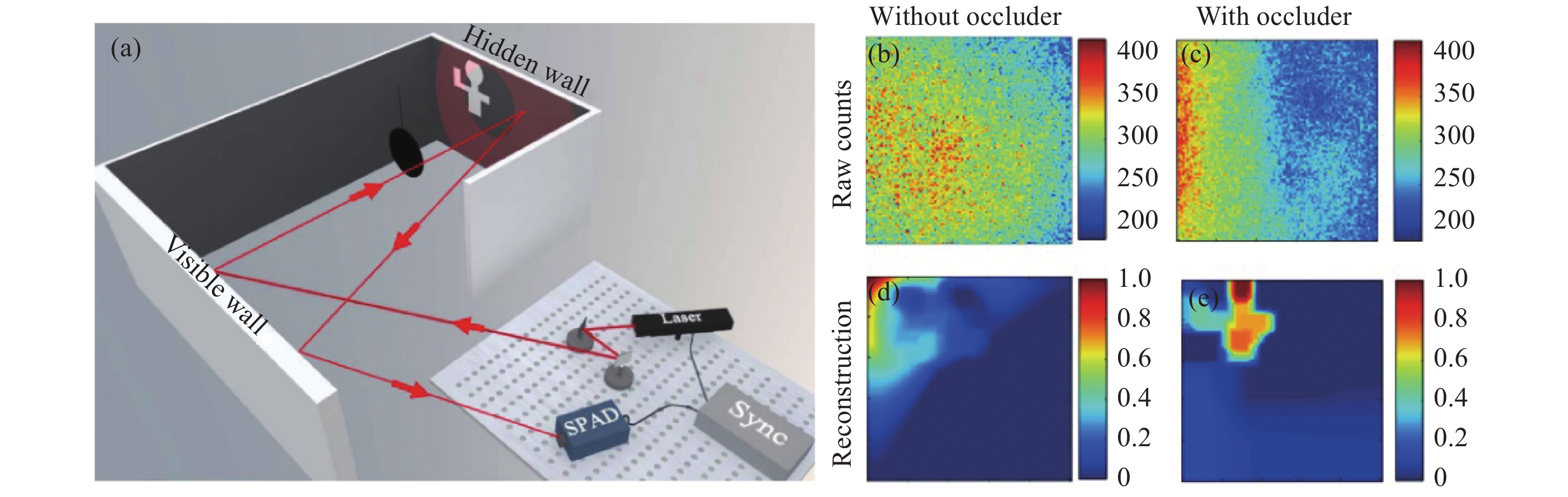
2018年,中国科学技术大学的徐飞虎等人提出利用SPAD加扫描摆镜实现预遮挡的非视域成像方法[27]。实验中所使用的是亚ns的脉冲激光器,重频40 MHz,波长为640 nm,平均功率为8 mW。在他们的方法中,探测器无需具有高的时间分辨,但是需要预先在目标和中介面间增加了一个遮挡物,而这个遮挡物可以有效消除目标各处光场在中介面上形成的混叠。通过构建光场正向传输模型,利用最优化方法实现图像的重构,见图11。

Figure 11. Experimental results of pre-occlusion non-line-of-sight imaging [27]. (a) Experimental configuration; (b) Raw data in the absence of an occluder; (c) Raw data in the presence of the occluder; (d) Reconstructed image in the absence of an occluder; (e) Reconstructed image in the presence of the occluder
2018年,美国斯坦福大学的Matthew O’Toole等人提出了一种基于光锥变换的共焦非视域成像系统[28]。该成像系统采用了激光雷达研究领域中常用的收发合置扫描方式,使得在中介面上的发射照明点和接收成像点始终重合在一起。实验中利用单点SPAD作为探测器,时间分辨率为27 ps。所采用的光源是波长为670 nm的脉冲激光器,平均功率仅为0.11 mW,脉宽为30.6 ps,重频10 MHz, 通过摆镜对场景进行了64×64/32×32个点的扫描。该系统可在65 cm的距离下获得3.1 cm的重建分辨率,重建时间小于1 s,但是受激光功率和摆镜速度的限制,其采集时间长,从几分钟到1 h的量级,见图12。
Figure 12. Confocal non-line-of-sight imaging system based on Light Cone Transform (LCT)[28]. (a) Schematic diagram of principle; (b) Experimental setup; (c) Reconstructed image
2019年,斯坦福大学和卡耐基梅隆大学的David B. Lindell等人提出了一种基于频率波矢迁移的共焦非视域成像系统[29]。该成像系统也采用了收发合置扫描方式。实验中所采用的光源是波长为532 nm的脉冲激光器,脉宽为35 ps,平均功率达到1 W,重频10 MHz,通过摆镜对场景进行了32×32/64×64/512×512个点的扫描。利用选通型单点SPAD作为探测器,选通时间40 ns,系统总的时间分辨为70 ps。由于采用了功率较大的激光器,因此该系统在近距离下可快速完成信号采集,实验中实现了2~4 Hz的动态成像,分辨率为十几厘米。在几十分钟的长采集时间下,分辨率可达几厘米量级,见图13。

Figure 13. Confocal non-line-of-sight imaging experimental results based on frequency-wavenumber migration(f-k Mig)[29]. (a) Experiment scene; (b) Line-of-sight view; (c) Measured data; (d) Reconstructed image
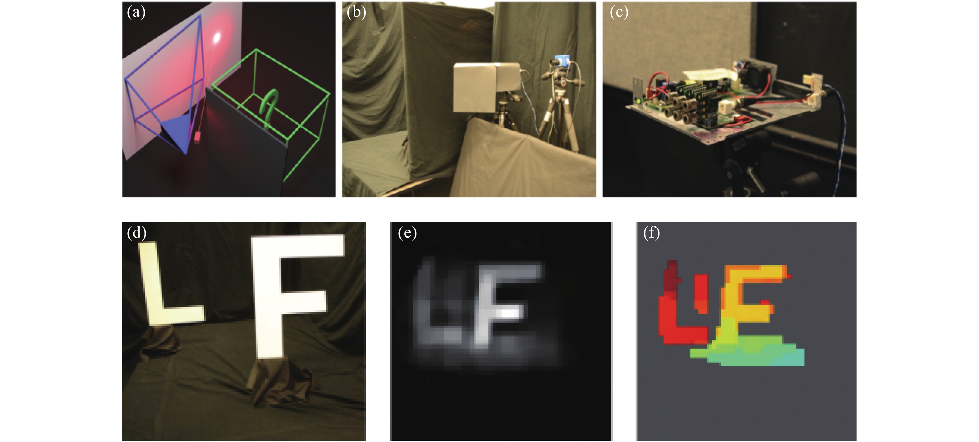
2019年,威斯康辛大学和萨拉戈萨大学的Xiaochun Liu 等人提出了一种基于虚拟波的非视域成像系统[30]。实验中利用选通型单点SPAD作为探测器,时间分辨率为30 ps。所采用的光源是波长为532 nm的脉冲激光器,脉宽为35 ps,平均功率达到1 W,重频10 MHz,通过摆镜对场景进行了180×130个点的扫描,采集时间从24 s~20 min。利用虚拟波算法进行了图像重建,重建分辨率达到几厘米量级,见图14。

Figure 14. Experimental results of non-confocal non-line-of-sight imaging experiment result based on phasor-field virtual wave[30]. (a) Imaging system; (b) Target; (c) Reconstructed image
2020年,威斯康辛大学的Marco Renna等人先利用两个单点SPAD实现了动态中介面下的非视域成像[31],之后和米兰大学的学者利用特殊定制的SPAD线列来进行非视域扫描成像[32]。实验中利用选通型16×1 SPAD作为探测器,时间分辨率为50 ps,选通时间60 ns。所采用的光源是波长为532 nm的皮秒脉冲激光器,平均功率达到1 W,重频10 MHz,通过摆镜对场景进行150×150个点的扫描,采集时间8 min。对于每一个独立的像元,通过简单的反投影算法即可还原出理想的目标图像,重构分辨率达到几厘米量级,见图15。
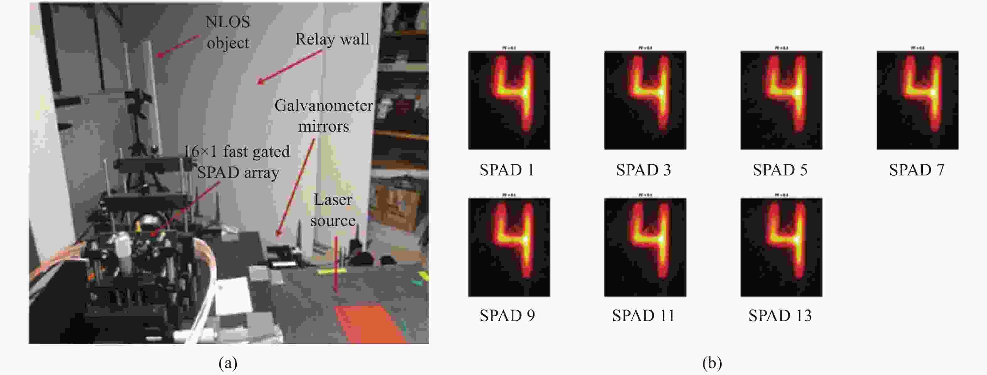
Figure 15. Experiment results of scanning non-line-of-sight imaging with SPAD linear array[32]. (a) Imaging system, scene; (b) Restored 3D images by different pixels, respectively
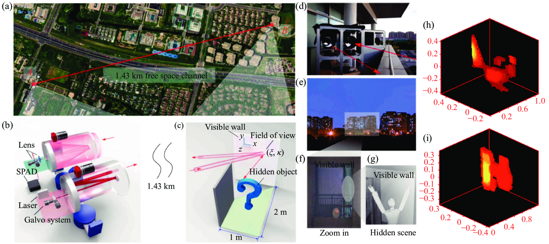
2021年,中国科学技术大学的Cheng Wu 等人提出了一种用于远距离探测的双扫描非视域成像系统[33](图16)。实验中利用选通型单点SPAD作为探测器,时间分辨率为210 ps,所采用的光源是波长为1550 nm的脉冲激光器,脉宽为500 ps,平均功率达到300 mW,重频1 MHz, 采用280 mm大口径的卡塞格林光学天线增加光能利用率。通过收发摆镜组对1.43 km远的场景进行64×64点的精细化扫描,单扫描点的曝光时间为2 s。利用改进后的最优化算法进行了图像重建,重建分辨率达到9.4 cm。

Figure 16. Experiment results of dual scanning non-line-of-sight imaging system[33]. (a)-(g) Experiment scene and system; (h), (i) Imaging results
表1将几种典型的非视域成像系统的主要性能进行列举,主要从探测器、光源和重构图像的性能参数进行对比。不难看出表中大多数的激光光源脉宽都在fs到百ps量级,远小于探测器的时间分辨率。即在系统层面,目前非视域成像系统的成像分辨率及成像质量主要受限于探测器的时间分辨率。从研究趋势看,非视域成像系统的探测器历经了条纹管相机、选通型增强相机、光子混频器、SPAD几代器件的发展。条纹管相机的优点是测时分辨率可达几个ps甚至fs,灵敏度较高,不足是尺寸大,价格昂贵,集成度低;选通型增强相机优点是灵敏度高,空间分辨率高,不足是价格昂贵,时间分辨率低,一般为ns量级;光子混频器件优点是集成度高,价格便宜,不足是灵敏度低,需长时间曝光。由于SPAD具有单光子灵敏度、皮秒量级的时间分辨率、易集成和低成本等诸多优点,目前已成为非视域成像的首选器件。近年来非视域成像的研究几乎都是围绕着单点SPAD加扫描摆镜的基本成像构型开展的。但是单点扫描这种成像构型能量利用率极低,需要大功率激光照明加以弥补,又由于存在扫描装置,不仅信号采集速度难以提升,体积功耗也受到极大的限制。未来根本的解决方法是采用SPAD面阵进行无扫描阵列式非视域成像。
Institutions Detectors Lasers Imaging performance Massachusetts Institute
of Technology [1-2]Streak Camera Tr: 2 ps
Pixel: 672×1
St: 300-1200 sλ : 795 nm
τ: 50 fs
f: 75 MHz
Num: 60RS: 40 cm×40 cm×40 cm
l0: 25 cm
Ires: vertical 0.4 mm
Horizontal 5-10 mm
RT: 2-4 sFrench-German Research
Institute of Saint-Louis [16-17]ICCD GW: 2 ns
Pixel: 1360×1024λ: 532 nm
τ: 2 ns
f: 21 kHz
W: 18 μJSize: 10 in×10 in
l0: 2 m
Ires: limited by gate widthThe University of British Columbia
and University of Bonn [18, 20]PMD MBW: 110-180 MHz
Pixel: 120×160
St: 4 minλ: 650 nm
τ: 2-3 ns
P: 1.5 W
RS: 1.5 m×1.5 m×2 m
l0: 1.5 m
Ires: a few centimeters -
more than ten centimetersStanford University [28] Single-pixel SPAD
(Confocal LCT)Tr: 27 ps
Pixel: 1
St: a few minutes
to one hourλ: 670 nm
τ: 30.6 ps
f: 10 MHz
P: 0.11 mW
Num:
64×64/32×32RS: 1 m×1 m×1 m
l0: 40-115 cm
Ires: 3.1 cm@65 cmStanford University and
Carnegie Mellon University [29]Single-pixel SPAD
(Confocal f-k)Tr: 70 ps
Pixel: 1
St: 0.25 s-180 minλ: 532 nm
τ: 35 ps
f: 10 MHz
P: 1 W
Num:
512×512/64×
64/32×32RS: 2 m×2 m×1.5 m
l0: 1 m
Ires: a few centimeters -
more than ten centimetersUniversity of Wisconsin and
University of Zaragoza [30]Single-pixel SPAD
(Virtual waves)Tr: 30 ps
Pixel: 1
St: 24 s-20 minλ: 532 nm
τ: 35 ps
f: 10 MHz
P: 1 W
Num: 180×130RS: 1.8 m×1.3 m×5.1 m
l0: 0.5-5.1 m
Ires: a few centimeters @0.5 mUniversity of Milan and
University of Wisconsin[32]Linear-array SPAD Tr: 50 ps
Pixel: 16×1
St: 8 minλ: 532 nm
f: 10 MHz
P: 1 W
Num: 150×150Size: 40 cm×60 cm
l0: 1 m
Ires: a few centimeterFrench-German Research
Institute of Saint-Louis [22]Planar-array InGaAs SPAD Tr: 250 ps
Pixel: 32×32
St: 340 msλ: 1.545 μm
τ: 500 ps
f: 100 kHz
W: 3 μJSize: 25 cm×25 cm
l0:1.8 m
Ires: approximate locationHeriot-Watt University [23] Planar-array
Si SPADTr: 110 ps
Pixel: 32×32
St: 3 sλ: 800 nm
τ: 10 fs
f: 67 MHz
W: 10 nJSize: 30 cm×10 cm×4 cm
l1: about 1 m
Ires: objects positioning and tracking
with centimeter accuracyNotes: 1. Tr: Time resolution; 2. Pixel: Pixel elements; 3. St: Sampling time; 4. λ: Wavelength; 5. τ: Pulse width; 6. f: Repetition frequency; 7. Num: Scan points; 8. P: Power; 9. W: Energy; 10. MBW: Modulation bandwidth; 11. GW: Gated width; 12. RS: Reconstruction space; 13. l0: Distance of object to diffuse wall; 14. l1: Distance of object to detector; 15. Size: Object size; 16. Ires: Image resolution; 17. RT: Reconstruction time Table 1. Main performance parameters of a typical non-visual imaging system
(2)非视域成像算法的研究进展
非视域成像算法最早采用的是类似于医学CT领域常用的反投影方法。2012年,Otkrist Gupta等人就是利用反投影算法处理条纹相机采集到的实验数据,从而还原出非视域目标的三维图像[2]。该算法一般包括反投、滤波、取阈三个步骤,反投过程中将采集好的多组时间信号按照几何关系投射到空间中形成投影图,然后对投影图进行滤波运算锐化图像边缘,再通过取阈值去掉较弱的伪影干扰。由于无法像CT那样进行大角度范围观测,“丢失锥”效应严重,获得的三维图像存在着较大的畸变和伪影。Martin Laurenzis 等人对反投影算法进行改进,在滤波过程中引入了拉普拉斯三维滤波算子,同时考虑了信号特征选择以及不同帧数据间的联系[34-35],使得成像分辨率获得一定程度的提升。Victor Arellano等人进一步提出了快速反投影算法,使其可以借助GPU进行并行运算,在不损失重建分辨率的前提下使重建速度获得大幅度的提升[36],见图17。

Figure 17. Processing results of the fast back projection algorithm[36]. (a) Normal back projection algorithm; (b) Fast back projection algorithm; (c) Target; (d) System
Marco La Manna等人提出了两种迭代反投影算法,即加性误差反投影(AEB)和乘性误差反投影(MEB)[37],研究结果表明:迭代反投影算法能够提供比非迭代反投影算法更好的重建分辨率,但对光场正向传输模型中的误差更敏感,重建时间更长。西安电子科技大学的李海瑞等人改进了非视域成像中的反投影算法,进行二值化投射累积,提高了算法效率,仿真结果也表明该方法可增强遮挡目标重构的效果[38]。哈尔滨工业大学的靳辰飞等人提出了基于时间波形反卷积的反投影方法重建非视域目标[39]。该方法利用Richardson–Lucy 反卷积方法有效地提高了信号的时间波形分辨率,然后再利用反卷积后的时间波形重构出高分辨的非视域三维像。同年他们提出了基于椭球模式分解的非视域多目标成像方法[40]。该研究提出在原始投影图像中利用参数估计的方法对多个目标进行迭代分离,然后对各个目标进行单独处理,消除各个目标间伪影的相互干扰,获得高分辨的多目标三维重构像。
另一种重建算法是数学上常用的最优化方法。2014年,Felix Heide 等人利用最优化算法处理光子混频器件采集到的实验数据,成功还原出非视域目标的三维图像[18]。该方法通过前期对场景的严格标定处理,可精确建立光场在场景中的正向传输模型,从而将隐藏目标的重构简化为一个线性反问题的求解。在求解的过程中引入了额外的先验信息对问题进行正则化,包括真实物体的几何稀疏性和非负性等先验。然后通过交替方向乘子法(ADMM)进行最优化求解,通过几个小时的反复迭代不断逼近真实的解。后来,他们又利用改进后的最优化算法处理单点SPAD采集到的实验数据,在模型建立中考虑了目标的表面方向和目标间的相互遮挡的影响,还原出更为精准的三维图像[41](图18)。该算法在小型计算服务器上耗时2 h才能算得一幅图像,占用内存768 GB。美国麻省理工学院的Achuta Kadambi等人系统地分析了场景反射率特性对非视域成像的影响,通过严格的理论建模,用最优化方法实现了非视域图像的重构[42]。2017年,Adithya Kumar Pediredla等人提出一种最优化算法,称为参数化平面拟合方法,可高保真地重建隐藏体积中的单个平面和由多个平面墙组成的整个多边形房间[43]。

Figure 18. Processing results of the optimization algorithm considering the direction of the target surface and the occlusion between the targets[41]. (a) Measured data; (b) Linear optimization reconstruction; (c) Improved optimization reconstruction
2019年,浙江大学的Luzhe Huang等人提出了一种基于贝叶斯统计的非视域算法,利用信号的时间、空间和强度信息建立基于贝叶斯统计的后验概率模型,利用最优化算法进行求解[44]。与传统的反投影方法相比,该算法能够处理数据中的随机误差,成像质量更高。最近,中国科学技术大学的Jun-Tian Ye等人提出了基于压缩感知的最优化重建方法[45],他们利用了非视域图像的稀疏特征,采用SPIRAL-TAP算法实现对目标的重建,这种方法可以有效减小空间采样的数量。实验中他们用5×5的扫描点数实现了64×64的空间分辨。
2018年,Matthew O’Toole等人在共焦非视域成像系统的基础上,提出了与之相匹配的光锥变换算法[28](图19)。该算法充分利用了共焦非视域成像构型的几何光路特点,可将瞬态光场的正向传输模型演变成为一个空移不变性系统,然后通过傅里叶变换可以很方便地求解目标的三维图像。该算法不仅速度快,占用内存少,而且重建分辨率较高。后续该团队进一步提出了基于方向的光锥变换算法,该方法将隐藏物体的反照率和表面法线两个信息联合,最终重构的曲面结果相较之前更精确、重建时间更短[46]。

Figure 19. Processing results of the LCT algorithm and other algorithms[28]. Processing results of back projection(a), filtered back projection(b), LCT(c), and LCT+ optimization(d)
2019年,David B. Lindell等人在共焦非视域成像系统的基础上,提出了另一种与之相匹配的频率波矢迁移算法[29](图20)。该算法的灵感来源于地震学中利用地震波来回溯震源的波动迁移算法,它可以利用傅里叶变换实现时频域到波矢域的转换,给出目标的精确解析解。该算法不仅速度快,占用内存少,重建分辨率高,而且不受材料散射特性的影响。但是该算法仍依赖共焦非视域成像构型,虽然理论上可近似实现非共焦的阵列式非视域成像构型,但是仅在一定范围内可行,而且重构误差较大。

Figure 20. Processing results comparison of frequency wave vector migration(f-k Mig) and other algorithms[29]. Processing results of target(a), measurement data(b), filtered back projection(c), LCT(d), f-k Mig(e)
2019年,Xiaochun Liu 等人提出了一种虚拟波成像算法[30],该方法可将非视域三维成像抽象成为波动衍射成像问题,为重建算法的研究提供了一条新的解决途径。该方法在采集到的数据基础上,通过虚拟构造一种波动的照明、传输、成像过程来重构三维物体,目前已经在单点扫描非视域成像系统上进行了实验验证,但是该方法成像分辨率和重构时间都依赖于成像系统的构型和虚拟测量过程的构造,对参数的选择比较敏感。由于可采用反投影算法作为其运算内核,所以其重构时间和反投影方法接近。该方法理论上适用于非共焦成像系统,见图21。
表2将目前主流的非视域成像算法进行了一个性能对比。从成像算法来看,目前反投影方法依然是比较流行的一种方法,其运行时间和占用内存方面相对现有计算机水平可以接受。但是由于无法像CT那样进行大角度范围观测,“丢失锥”效应严重影响恢复质量。而最优化方法虽然重构分辨率高,但该方法不仅要求构建的模型精确度高,而且极其消耗计算时间和存储空间。
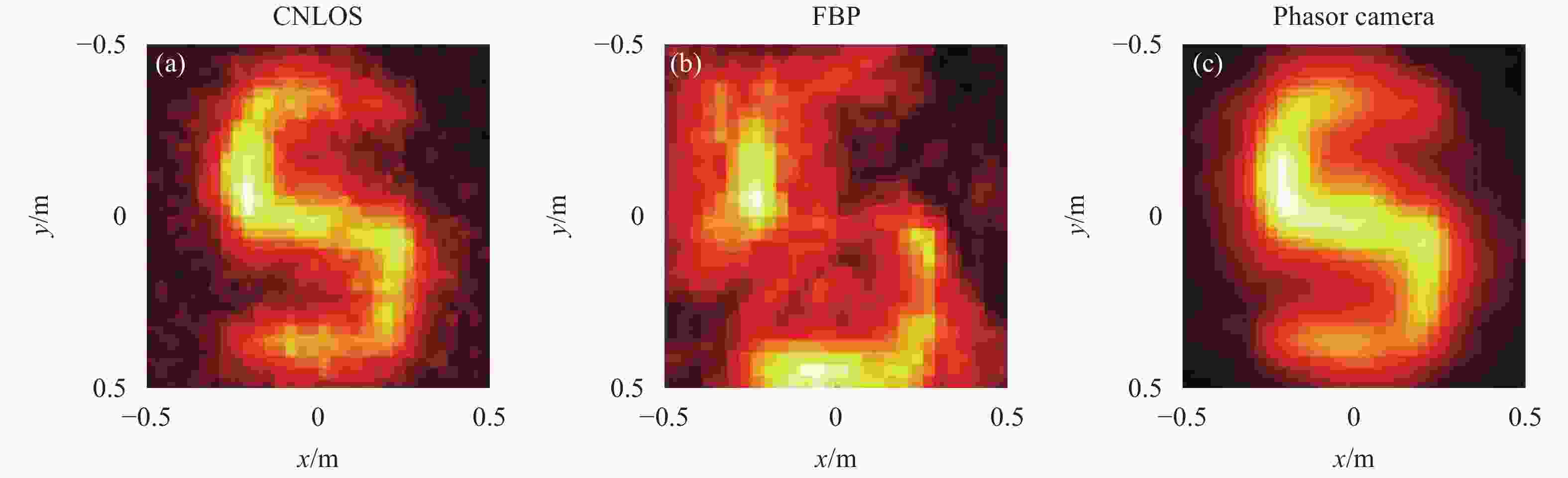
Figure 21. Processing results of the phasor-field virtual wave algorithm[30]. Processing results of confocal LCT (a), filtered back projection (b), virtual wave (c)
FBP LCT f-k Virtual waves Optimization
(single iteration)Runtime ${{O} }({N^5})$ ${{O} }({N^3}\log N)$ ${{O} }({N^3}\log N)$ ${{O} }({N^5})$ ${{O} }({N^5})$ Memory ${{O} }({N^3})$ ${{O} }({N^3})$ ${{O} }({N^3})$ ${{O} }({N^3})$ ${{O} }({N^5})$ Quality Low Mid-high Mid-high Mid-high High Configuration Confocal or
non-confocalConfocal Confocal or
approximately non-confocalConfocal or non-confocal Confocal or
non-confocalTable 2. Performance comparison of different NLOS imaging algorithms
后期出现的光锥变换和频率波矢迁移算法在重建时间和重建分辨率方面都展示了极佳的性能,但是这两种方法都仅能用于收发合置的共焦扫描成像构型,无法精确用于更有应用潜力的阵列式非视域成像构型中。虚拟波算法同样是基于单点扫描非视域成像系统建立起来的,但其理论上是完全适用于非共焦成像系统的,其运行时间和存储空间与反投影相当,而重构质量远优于后者,如果选用更好的计算内核和虚拟波参数,未来各项指标提升的空间很大。除上述提到的几种非视域成像算法,还有基于费马路径理论进行非视域形状重建方法[47]、以及基于神经网络的数据驱动方法[48-49]等。目前数据驱动方法重建精度较高,但前期需要进行大量的样本学习来提高神经网络的学习正确率,需要的先验信息较多、时间成本较大。
-
到目前为止,非视域三维成像激光雷达的可行性已得到了前期研究的验证,目前研究者们重点研究解决这种激光雷达新体制未来走向实际应用所要面临的瓶颈问题。实际应用中多数情况下需要较高的成像分辨率和较快的成像速度。其中无人驾驶是非视域成像的一个主要应用方向,特别是能够针对快速运动目标进行成像。然而目前非视域三维成像激光雷达的研究几乎都是围绕着单光子雪崩二极管(SPAD)加机械扫描的基本成像构型开展的,这种成像构型不仅能量利用率低,信号采集速度慢,体积功耗也受到很大的限制。未来如何实现将SPAD面阵代替单元SPAD进行无扫描阵列式非视域成像,有以下几个方面需要研究。
(1)首先,近几年SPAD的器件水平发展很快,大面阵的SPAD已经逐步商用化,但是在探测概率、时间分辨、暗计数等方面依然无法满足非视域成像的要求。
(2)其次,目前的主流算法中的非共焦算法依然无法满足应用场景对分辨率和运行时间的要求,下一步研究适配于面阵成像的非共焦成像算法将成为研究重点。目前来看,频率波矢迁移和虚拟波是可考虑的候选算法。随着人工智能的发展,数据驱动算法也有可能成为解决这个问题的有效途径之一。
(3)最后,太阳背景光、场景散射特性、照明方式、体积、质量、功耗等诸多因素也是限制该技术走向实际应用过程中必须解决的关键问题。
因此,非视域三维成像激光雷达的工程化仍需经历一段较长时间发展。未来在人工智能发展牵引下,这项由光学、电子学、数学以及计算机科学多学科交叉的新技术具有更为广阔的应用前景,必将吸引更多的研究者投入其中。


 DownLoad: