


HTML
-
二维成像技术在成像过程中丢失深度信息,三维成像技术的出现无疑是成像领域的重大突破,通过记录场景深度信息使人们更直观地获取视觉信息。全光三维成像技术是计算成像的重要研究方向,它将光学设计、光学原理与计算处理相结合,在一定程度上突破了传统光学设计的技术壁垒[1-2]。与传统的相机相比,全光相机在主物镜和探测器之间加入微透镜阵列(Micro Lens Array,MLA),只需一次拍摄即可获取位置信息和角度信息,通过分析不同视角图像之间的视差信息即可获得完整场景的三维点云数据,这为场景深度测量提供了数据基础[3-7]。
光场三维成像技术主要应用于目标识别、地形匹配、环境态势感知、工件检测、视觉SLAM以及城市数字化等领域。目前,全光相机三维成像技术主要应用于近距离场景,例如:生物医疗、高端工业检测以及粒子追踪等,而远距离三维成像的相关应用却少之又少[8]。同时,基于全光相机的三维成像技术是集前端光学系统与后端信息处理为一体的计算成像技术,目前对全光相机后端处理算法的研究颇多[2,6,9-13],对前端光学系统的研究鲜有报道。文中对前端光学系统设计进行研究,建立全光相机深度分辨率模型,分析前端光学系统光学性能对全光相机深度分辨率的影响,确定前端光学系统设计指标;分析两反光学系统各参数的影响,确定全光相机主物镜光学系统的初始结构,最后完成可应用于亚公里级三维成像的全光相机主物镜设计,该设计易于加工制造,可在110 ℃温度带宽下良好成像。
-
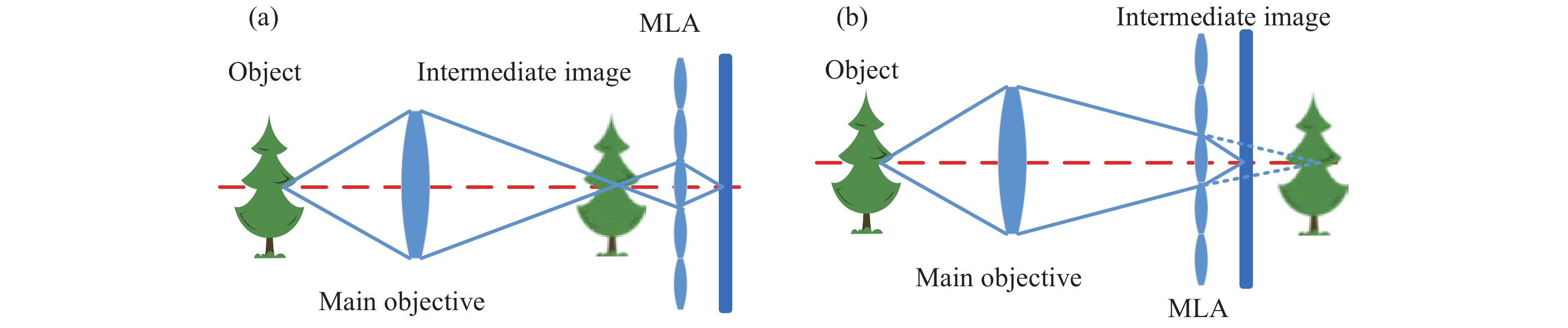
全光相机主要包括主物镜、微透镜阵列以及探测器[8],其可以分为非聚焦型和聚焦型两种基本形式。相较于非聚焦型全光相机,聚焦型全光相机拥有更高的空间分辨率,因此文中选择聚焦型全光相机进行讨论。图1所示为聚焦型全光相机的两种基本结构形式,场景中的物体经过主物镜成像在中间像面上,中间像面的物体经不同的微透镜单元在探测器的不同位置成像,即可完成位置信息和方向信息的记录。与开普勒结构全光相机相比,伽利略结构聚焦型全光相机可以将“近景变远,远景变近”,通过牺牲近端深度分辨率实现远端深度分辨率的提升。因此,文中选择伽利略结构形式进行研究。

Figure 1. (a) Kepler telescopic plenoptic camera; (b) Galileo telescopic plenoptic camera
-
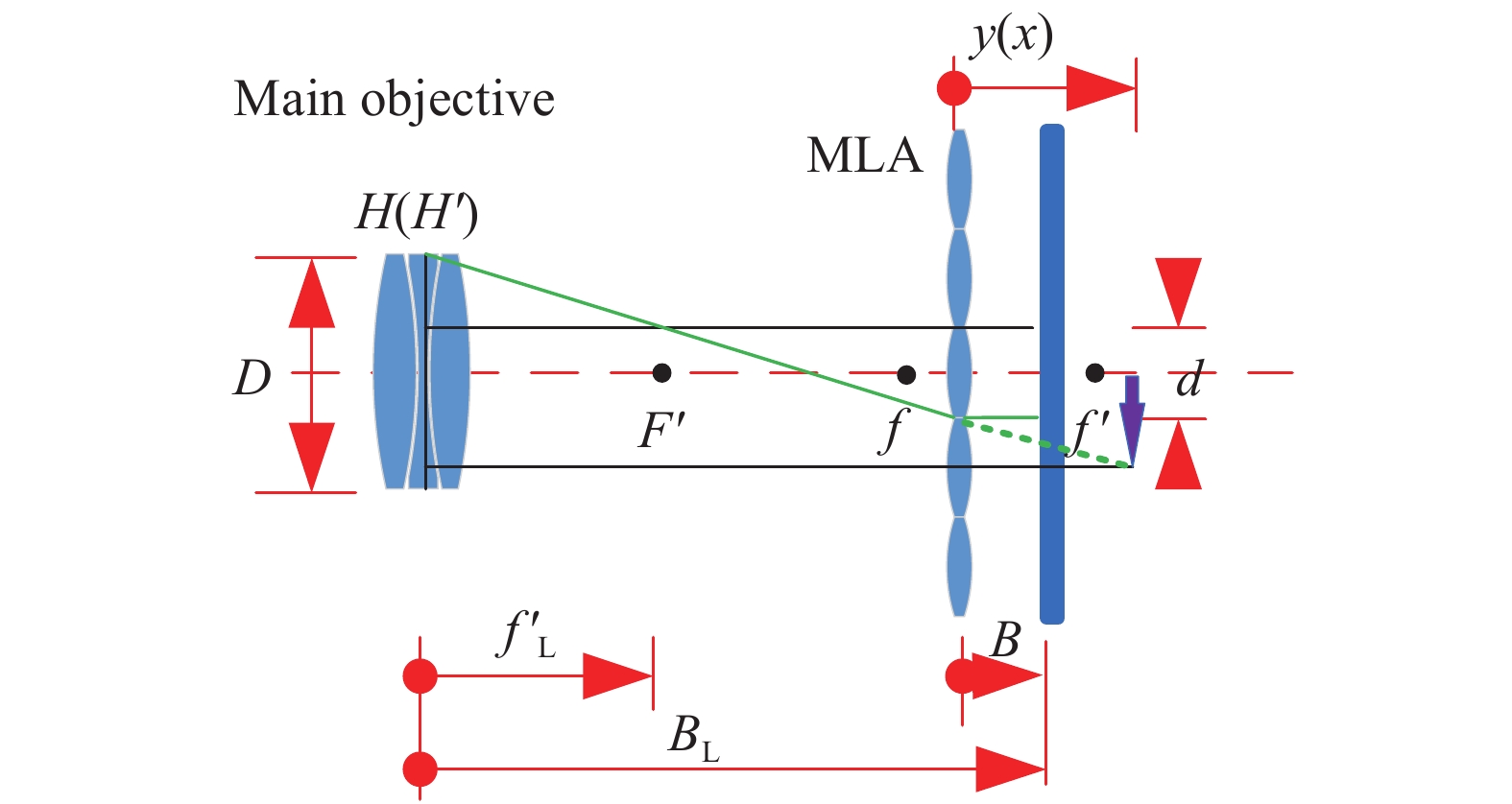
若微透镜单元的成像范围大于其空间尺寸,则子图像互相叠加,产生串扰;若微透镜单元的成像范围小于其空间尺寸,则子图像间产生空像素,造成传感器资源浪费[14-15]。图2所示为全光相机F#匹配示意图,根据相似三角形,对于远距离三维成像全光相机有:

Figure 2. Plenoptic camera F# matching
式中:
$ v\left(x\right) = {{y\left( x \right)} / B} $ 为虚深度;$F{\# _{\rm{L}}}$ 为主物镜的F#;$N = {B / d}$ 为微透镜阵列的工作F#。 -
聚焦型全光相机的横向分辨率为探测器分辨率的
${B / {y\left( x \right)}}$ 倍,由于光学系统传递时空信息的总量保持恒定,图像中${{y\left( x \right)} / B}$ 的信息发生重叠[16]。即理论横向分辨率极限为:式中:
${l_x}$ 和${l_y}$ 分别为探测器的水平分辨率和垂直分辨率。此外,主物镜焦距越长,视场角越小,图像可分辨的细节越多。 -
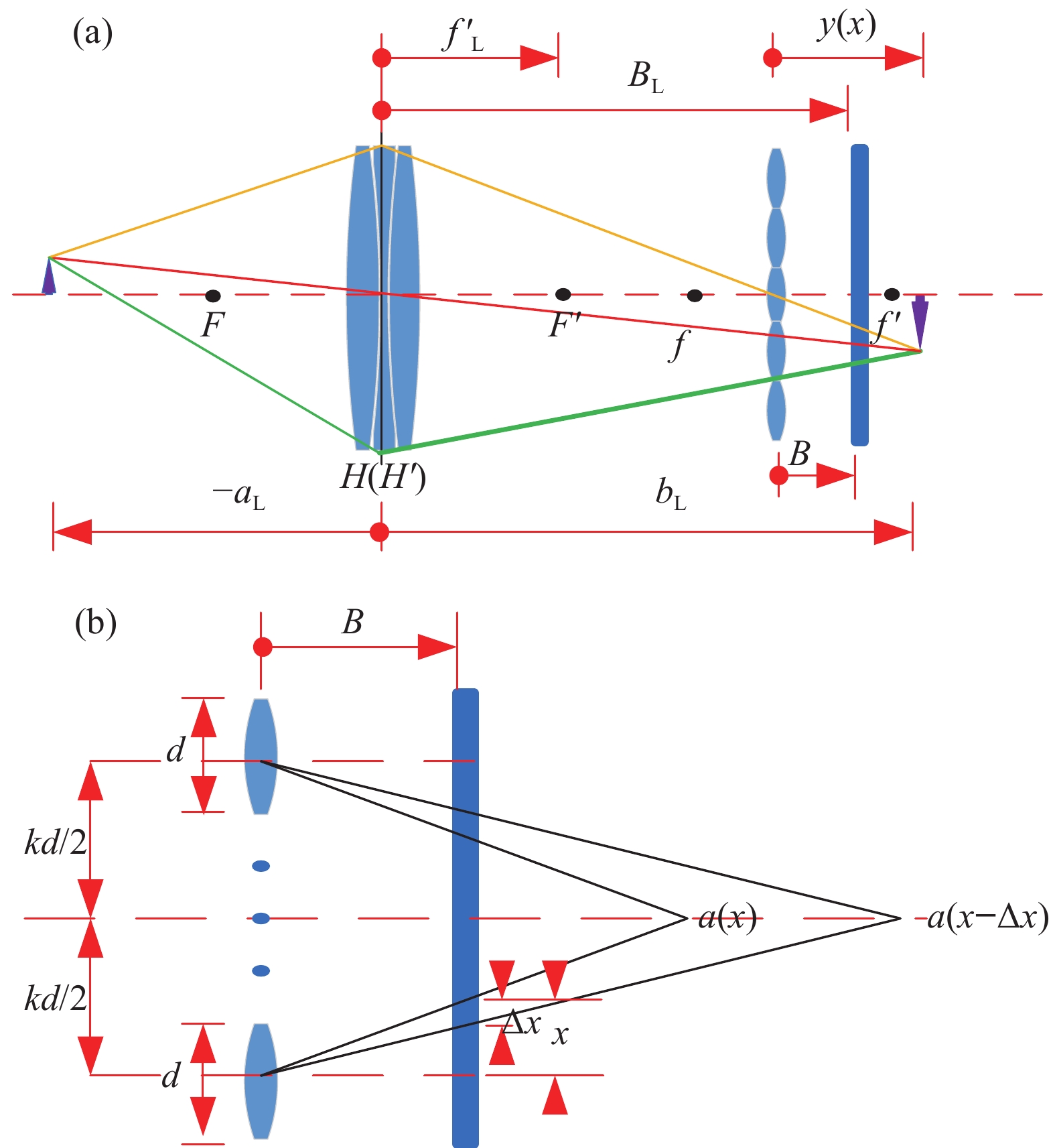
伽利略结构全光相机空间深度分辨率计算光路如图3所示。随着像点相对微透镜光轴的横向距离
$x$ 的变化,穿过两个微透镜的光线将相交于物空间的不同深度处。当$\Delta x$ 为一个像元大小时(不考虑亚像素识别),可以计算出主物镜像空间处的深度分辨率,根据成像高斯公式,可以进一步得到物空间中的深度分辨率。由相似三角形易得[17]:
Figure 3. (a) Calculation light path diagram of depth resolution of Galileo structure plenoptic camera; (b) Partial enlarged view
主物镜将物成像到中间像面,微透镜阵列再将该虚像二次成像到传感器上,由几何关系和高斯公式可得物方深度分辨率
$\delta $ 为:式中:
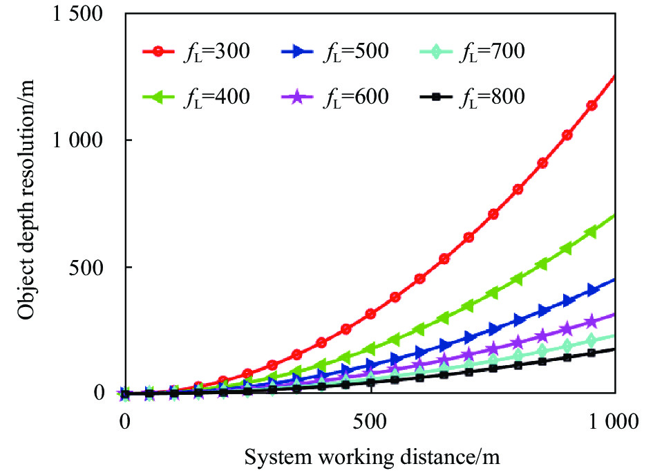
$\Delta x$ 为最小可分辨视差,考虑到算法的亚像元识别,在实际设计中取$\Delta x = \rho M$ ;$k$ 为描述两个微透镜间距的比例系数;$\nu \left( x \right)$ 为虚深度。图4为不同焦距下物方深度分辨率与系统工作物距的关系曲线,可以看出,相同工作物距下,焦距越长,物方深度分辨率越高。对于远距离三维成像,为满足纵向分辨率需求和空间适应性,采用折反光学系统进行主镜设计。

Figure 4. Relationship curve between object depth resolution and system working object distance under different focal lengths
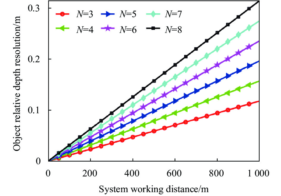
定义纵向分辨率与系统工作物距的比值为相对分辨率,即
图5表明系统的F#对深度分辨力的提升呈线性关系,因此,远距离三维成像可以在满足加工能力的基础上设计小F#、长焦距的系统来提升物方深度分辨率。且F#会影响微透镜阵列与探测器的相对距离,为了降低装调难度,F#不宜过小。

Figure 5. Influence of system working distance on depth resolution under different F/#
由公式(4)及图3、图4可以看出,对于远距离三维成像,为保证目标横向分辨率以及纵向深度分辨率,全光相机主物镜应采用长焦距、小F#为宜,考虑设计、加工、装调等工程化问题,在满足分辨率需求的情况下,应选择适宜的F#进行设计。同时,在体积需求有限的情况下,首先考虑采用折反结构进行主物镜光学系统设计。
-
图6所示为两反系统的基本结构,图中
${D_1}$ 为主镜的通光口径,${D_2}$ 为次镜的通光口径,$d$ 为主镜和次镜之间的距离,$l_1'$ 为主镜到中间像面的距离,$l_2'$ 为次镜到像面的距离,$\delta $ 为主镜到像面的距离。
Figure 6. The basic structure of the two anti-system
若系统遮拦比
$\alpha > 0$ ,次镜的放大倍率$\;\beta < 0$ 时,根据成像高斯公式和图6可得:式中:
${R_1}$ 为主镜的曲率半径;${R_2}$ 为次镜的曲率半径[18]。系统总长
$L$ 取决于$\left| {l_2'} \right|$ 与$\left| d \right|$ 之间的较大者,即会聚光路中系统满足:①
$\alpha $ 与$\;\beta $ 反号,且主镜一定是凹面;②遮拦比$\left| \alpha \right| < 1$ [19]。抛物面的加工检测相对容易且可以增加设计自由度,因此设计采用抛物面主镜。当反射组件只校正球差时,有由图7可知,次镜的二次曲面系数随次镜放大倍率的增大而增大,
$e_2^2$ 越小,次镜越容易加工,因此希望$\;\beta $ 取小值;但$\;\beta $ 越小,次镜的公差越严格,因此在设计时要对二者进行权衡,选择合适的$\;\beta $ [20]。
Figure 7. Relationship between the secondary mirror quadric coefficient
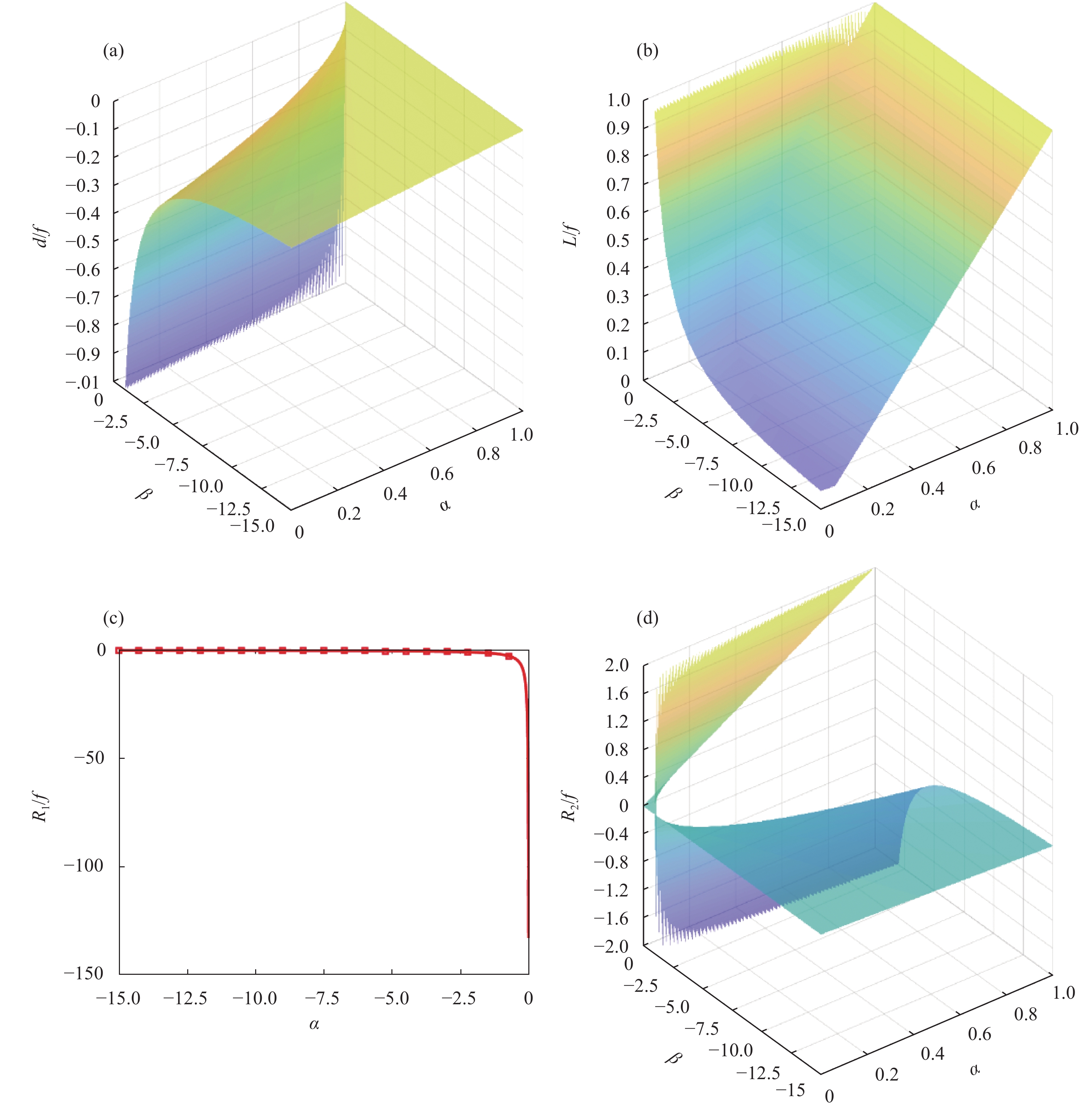
$e_2^2$ and the blocking ratio$\alpha $ and the secondary mirror magnification$\;\beta $ 如图8(a)所示,当
$\alpha $ 一定时,$d$ 与$\;\beta $ 成反比,且$\left| d \right|$ 随着$\;\beta $ 的增大而增大;当$\;\beta $ 一定时,$d$ 与$\alpha $ 正相关。如图8(b)所示,系统总长与$\alpha $ 和$\;\beta $ 成正比,$\alpha $ 和$\;\beta $ 应该尽可能取小值。如图8 (c)所示,${R_1}$ 与$\;\beta $ 成反比,同时为了保证系统的稳定性和可靠性,不应在$\;\beta \in \left( { - 1.5,0} \right)$ 范围内进行取值。如图8 (d)所示,当$\alpha $ 一定时,${R_2}$ 与$1{\rm{ + }}\;\beta $ 成反比,$\;\beta $ 应尽可能小;当$\;\beta $ 一定时,${R_2}$ 与$\alpha $ 成正比,${R_2}$ 随着$\alpha $ 的增大而增大。
Figure 8. (a) Relationship between the distance between d , α and β; (b) Relationship between L and α; (c) Relationship between R1 and β; (d) Relationship between R2 , α and β
-
设计指标要求如表1所示。在设计中考虑探测器的像元为
$3.45$ μm,算法可达到${1 / 8}$ 像素亚像元识别精度,即$M = 8$ 。根据公式(4),同时考虑设计、加工、装调等工程化问题,为达到设计要求,主物镜焦距为$500\;{\rm{mm}}$ ,系统F#为5,MLA通光孔径为$0.2\;{\rm{mm}}$ ,三种焦距分别为${f_1} = 0.93\;{\rm{mm}}$ ,${f_2} = 0.83\;{\rm{mm}}$ 和${f_3} =0.74\;{\rm{mm}}$ 。Index Parameter Distal range $500$ m Depth resolution $ \leqslant 5$ m Wavelength Visible light Space volume requirements $\phi 110 \times 150$ Operating temperature −40-70 ℃ Table 1. Index requirements
-
根据1.5节模型分析,确定设计中取
$\alpha {\rm{ = }}0.3$ ,$\;\beta {\rm{ = }} - 4$ ,最终优化结果的光学系统光路如图9所示。常温条件下系统的F#=5,系统焦距为$500\;{\rm{mm}}$ ,系统总长为${\rm{162.5}}\;{\rm{mm}}$ 。该设计为折反结构且反射组件中主镜为抛物面,次镜为双曲面,折射光学元件均为球面,便于加工检测。
Figure 9. Light path diagram of optical system
设计中主要采用MTF、场曲和畸变等进行像质评价,如图10所示。

Figure 10. Image quality evaluation of optical system. (a) 25 ℃ MTF; (b) −40 ℃ MTF; (c) 70 ℃ MTF; (d) 25 ℃ field curvature and distortion; (e) −40 ℃ field curvature and distortion; (f) 70 ℃ field curvature and distortion
-
系统在实际公差作用下的MTF预计结果如表 2所示,该光学系统在不同温度下全视场MTF均大于0.26,成像质量较好,在满足实际需求的前提下具有一定的加工可行性。
FOV Theoretically
@20 ℃After tolerance
@20 ℃Theoretically
@−40 ℃After tolerance
@−40 ℃Theoretically
@70 ℃After tolerance
@70 ℃0 0.4303 0.3711 0.3105 0.2623 0.5147 0.4485 0.2 0.4469 0.3770 0.3492 0.2879 0.5044 0.4301 0.5 0.4125 0.3296 0.3828 0.3015 0.4013 0.3180 0.7 0.3825 0.3068 0.3635 0.2903 0.3655 0.2809 1.0 0.3842 0.2962 0.3679 0.2734 0.3614 0.2629 Table 2. MTF under tolerance@80 lp/mm
-
光场三维成像技术主要应用于目标识别地形匹配、环境态势感知、工件检测、视觉SLAM以及城市数字化等领域。随着远距离三维感知需求的不断提升,明确应用边界、拓展光场三维成像的作用距离成为亟待解决的问题。文中以双目立体视觉为基础建立全光相机光学系统参数分析模型,结合实际工程应用提出折反式光学系统各参数的选择方法,并给出了具体的设计实例,对此类光学系统的设计具有一定的指导意义。所设计的光学系统实现了−40~70 ℃的无热化,公差作用后全视场MTF在
$80\;{{{\rm{lp}}} / {{\rm{mm}}}}$ 处优于0.25,配合${1 / 8}$ 亚像素识别算法,在0.5 km处深度分辨率小于5 m。此外,建立了全光相机参数分析模型,并根据模型和公里级全光相机精度要求计算出了主物镜的参数和微透镜阵列的光学基本参数,后续将对该全光相机进行三维光场成像仿真,并对全光相机进行研制,最后进行实验对上述分析以及设计进行验证。


 DownLoad: