Volume 51 Issue 5
Jun.  2022
Turn off MathJax
Article Contents

Chen Jiayi, Wang Haichao, Li Bin, Liu Yong, Jiang Yanhui, Yao Liqiang. 0 g surface figure test of large aperture mirror supported by Bipod[J]. Infrared and Laser Engineering, 2022, 51(5): 20210604. doi: 10.3788/IRLA20210604
Citation: Chen Jiayi, Wang Haichao, Li Bin, Liu Yong, Jiang Yanhui, Yao Liqiang. 0 g surface figure test of large aperture mirror supported by Bipod[J]. Infrared and Laser Engineering, 2022, 51(5): 20210604. doi: 10.3788/IRLA20210604

0 g surface figure test of large aperture mirror supported by Bipod

doi: 10.3788/IRLA20210604
  • Received Date: 2021-08-25
  • Rev Recd Date: 2021-10-08
  • Publish Date: 2022-06-08
  • Bipod structure has the characteristics of static support and can isolate the additional mechanical load. Therefore, it has become one of the common support forms of large aperture space camera mirror assembly. When installing and adjusting on the ground, the surface figure of the mirror supported by the Bipod decreases due to the action of gravity. After the space camera enters the orbit, the surface figure of the mirror will change again with the release of gravity deformation. The gravity error of the mirror assembly is evaluated by finite element analysis method, and its accuracy is difficult to meet the requirements of high-quality and high-resolution imaging. At the same time, the gravity unloading scheme used in the mirror processing process is also difficult to be used to the component stage. In order to solve the problems of aliasing of assembly error and trefoil aberration and insufficient accuracy of spherical aberration test by detection light path in the process of gravity error test, a test scheme combining turnover and unloading was proposed. Based on the orthogonality of different aberrations, individual tests could be carried out to obtain each aberration item by item. Through the gravity turnover test of the mirror, the trefoil aberration in the assembly error and gravity error was separated. The unloading device with certain accuracy was designed. Through the comparative test before and after unloading, the spherical aberration caused by gravity, was obtained. By adopting the above scheme, the measurement of all gravity errors could be realized. The 1.3 m high-lightweight mirror assembly was tested. The gravity error surface figure (rms) and on-orbit surface figure (rms) are 0.192λ (λ=0.6328 μm) and 0.023λ, respectively.
  • [1] Zhang Chaojie, Xi Xinghua, Wang Yongxian, et al. Structural optimization design of large-aperture mirror for space remote sensing camera [J]. Infrared and Laser Engineering, 2020, 49(2): 0214002. (in Chinese) doi:  10.3788/IRLA202049.0214002
    [2] Feng Liangjie, Cheng Pengfei, Wang Wei. Design of Φ450 mm light-weighted SiC mirror subsystem in space-based astronomy telescope [J]. Infrared and Laser Engineering, 2021, 50(2): 20200175. (in Chinese) doi:  10.3788/IRLA20200175
    [3] Zhou Yuxiang, Shen Xia. Structure design of backside bipod flexure mount for space reflector [J]. Laser Technology, 2017, 41(1): 141-145. (in Chinese)
    [4] 连华东, 金建高, 宫辉. 空间反射镜Bipod结构设计研究 [C]//第二十三届全国空间探测学术交流会, 2010: 1-9.
    [5] Gao Chao, Chen Fang, Sun Haiyang. Design and error analysis of measurement structure for large aperture space camera mainboard [J]. Infrared and Laser Engineering, 2020, 49(10): 20200046. (in Chinese) doi:  10.3788/IRLA20200046
    [6] Jiang Yanhui, Liu Yong, Zou Baocheng, et al. Gravity unloading design of large aperture reflect mirror [J]. Environmental Technology, 2020(1): 81-85. (in Chinese) doi:  10.3969/j.issn.1004-7204.2020.01.019
    [7] Chen Hongda, Chen Yonghe, Shi Tingting, et al. Lightweight and mounting design for primary mirror in space camera [J]. Infrared and Laser Engineering, 2014, 43(2): 535-540. (in Chinese) doi:  10.3969/j.issn.1007-2276.2014.02.037
    [8] Sun Yixuan, Luo Shikui, Gao Chao, et al. Optimization method for large-aperture space mirror's gravity unload [J]. Infrared and Laser Engineering, 2020, 50(1): 20200103. (in Chinese) doi:  10.3788/IRLA20200103
    [9] Yang Qiushi, Zhang Jiyou, Yu Jianhai, et al. Research on error analysis of support deformation for large aperture space mirrors [J]. Spacecraft Recovery & Remote Sensing, 2020, 41(3): 60-70. (in Chinese) doi:  10.3969/j.issn.1009-8518.2020.03.007
    [10] Dong Deyi, Li Zhilai, Li Ruigang, et al. Simulation and experiment of influence of adhesive curing on reflective mirror surface [J]. Optics and Precision Engineering, 2014, 22(10): 2698-2707. (in Chinese) doi:  10.3788/OPE.20142210.2698
    [11] Meng Xiaohui, Wang Yonggang, Ma Xianmei, et al. Fabrication and test for Φ520 mm secondary mirror of on-axis three mirror space camera [J]. Infrared and Laser Engineering, 2017, 46(8): 0818002. (in Chinese) doi:  10.3788/IRLA201746.0818002
    [12] Wang Cong, Chen Jiayi, Li Mengjuan, et al. Centering of Φ1.3 m aspheric reflector based on interferometry [J]. Infrared and Laser Engineering, 2020, 49(1): 0113001. (in Chinese) doi:  10.3788/IRLA202049.0113001
    [13] Yang Liwei, Li Zhilai, Xue Donglin, et al. Extracting zero-gravity surface figure of mirror by orientation reversal [J]. Chinese Optics, 2016, 9(5): 606-612. (in Chinese) doi:  10.3788/co.20160905.0606
    [14] Chen Jiayi, Wang Haichao, Huo Tengfei, et al. Assembly for Φ1.3 m aperture telescope [J]. Optical Technigue, 2021, 47(1): 12-16. (in Chinese)
    [15] Zhou Yuming, Yang Qiushi, Meng Xiaohui, et al. Verification and application of gravity flip test method for large aperture optical components [J]. Spacecraft Recovery & Remote Sensing, 2019, 40(3): 33-39. (in Chinese) doi:  10.3969/j.issn.1009-8518.2019.03.005
  • 加载中
通讯作者: 陈斌, bchen63@163.com
  • 1. 

    沈阳化工大学材料科学与工程学院 沈阳 110142

  1. 本站搜索
  2. 百度学术搜索
  3. 万方数据库搜索
  4. CNKI搜索

Figures(7)

Article Metrics

Article views(152) PDF downloads(48) Cited by()

Related
Proportional views

0 g surface figure test of large aperture mirror supported by Bipod

doi: 10.3788/IRLA20210604
  • Beijing Key Laboratory of Advanced Optical Remote Sensing Technology, Beijing Institute of Space Mechanics & Electricity, Beijing 100094, China

Abstract: Bipod structure has the characteristics of static support and can isolate the additional mechanical load. Therefore, it has become one of the common support forms of large aperture space camera mirror assembly. When installing and adjusting on the ground, the surface figure of the mirror supported by the Bipod decreases due to the action of gravity. After the space camera enters the orbit, the surface figure of the mirror will change again with the release of gravity deformation. The gravity error of the mirror assembly is evaluated by finite element analysis method, and its accuracy is difficult to meet the requirements of high-quality and high-resolution imaging. At the same time, the gravity unloading scheme used in the mirror processing process is also difficult to be used to the component stage. In order to solve the problems of aliasing of assembly error and trefoil aberration and insufficient accuracy of spherical aberration test by detection light path in the process of gravity error test, a test scheme combining turnover and unloading was proposed. Based on the orthogonality of different aberrations, individual tests could be carried out to obtain each aberration item by item. Through the gravity turnover test of the mirror, the trefoil aberration in the assembly error and gravity error was separated. The unloading device with certain accuracy was designed. Through the comparative test before and after unloading, the spherical aberration caused by gravity, was obtained. By adopting the above scheme, the measurement of all gravity errors could be realized. The 1.3 m high-lightweight mirror assembly was tested. The gravity error surface figure (rms) and on-orbit surface figure (rms) are 0.192λ (λ=0.6328 μm) and 0.023λ, respectively.

    • 空间相机反射镜支撑的主要目的是在有效地进行定位的同时,隔离机械附加载荷,尤其是温度变化产生的附加载荷,减小反射镜面形变形,以保持空间相机成像质量[1-2]。静定支撑对机构的约束数量等于机构的自由度数量。当装配误差、温度变化引入形变时,静定支撑结构能够有效卸载,对反射镜不产生附加应力[3]。双脚架结构(Bipod)是大口径空间相机反射镜常用的一种准静定支撑结构。包括ASRTO-F空间望远镜、赫歇尔空间望远镜HSO、Pleiades相机、GEOEYE-1对地观测相机等在内的众多空间相机均采用了Bipod支撑形式[4-5]

      采用Bipod支撑的大口径反射镜在重力场的作用下,面形精度会下降。在地面装调时,反射镜的面形是包含了重力变形、装配应力以及加工残差等因素综合影响的结果。空间相机入轨后,随着重力变形的释放,反射镜面形发生改变[6]。为了评价空间相机的在轨成像质量,准确获取反射镜的零重力面形是大口径空间相机研制过程中的重要课题。GEOEYE-1空间相机采用基于有限元分析的方法评估主镜的在轨面形,而Kepler太空望远镜则使用气囊对主镜进行卸载,得到了rms为1/30λ的面形测试精度。

      文中分析了采用Bipod支撑的1.3 m口径反射镜在重力作用下的面形误差,阐述了零重力面形测试过程中的技术难点,提出了以仿真分析为指导的、分像差类别测试重力误差的技术方案,并进行了测试试验验证。

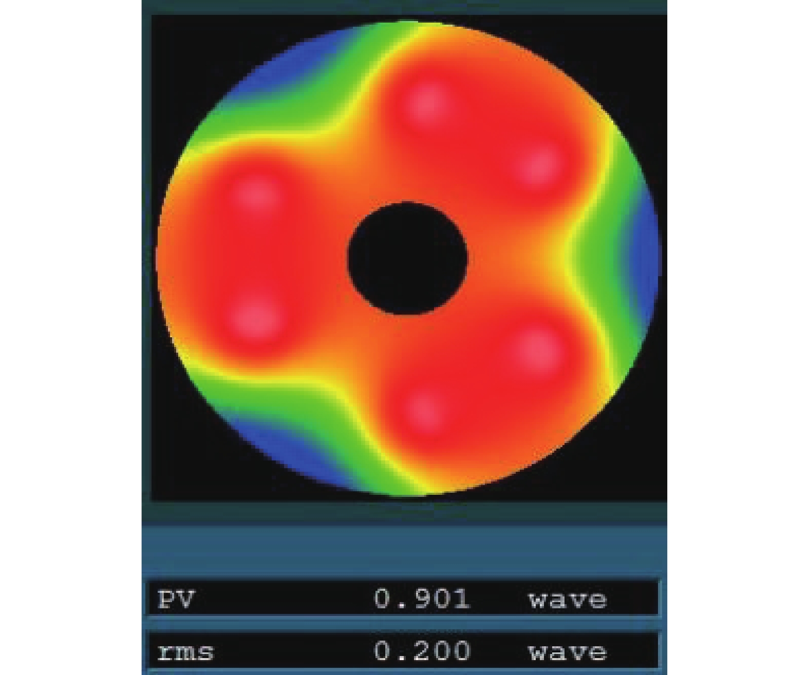
    • 1.3 m口径反射镜的材料为超低膨胀石英(ULE),轻量化率超过80%。运用有限元分析方法对反射镜组件在光轴竖直状态下受重力影响的面形进行分析。重力影响带来的面形变化为rms 0.200λ,其面形分布云图如图1所示。

      Figure 1.  Surface figure analysis result

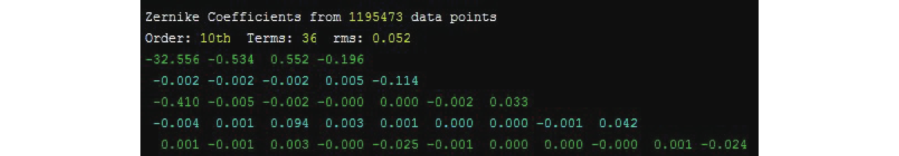
      利用泽尼克(Zernike)系数对该重力作用下的面形进行分析,图2为该面形的36项Zernike系数分析结果。Zernike系数中的Power、球差(Primary Spherical)、三叶像差(Trefoil)为主要误差,其数值分别为−0.196λλ=0.6328 μm)、−0.114λ、−0.410λ

      Figure 2.  Zernike coefficients of the gravity surface figure

      反射镜组件装配完成后,使用零位补偿检验法测试反射镜的重力面形,与有限元分析得到的面形进行对比,可以初步判断反射镜的面形精度。为了实现高质量、高分辨率成像,大口径空间相机的主镜在轨面形一般要求优于1/40λ甚至更高。由于反射镜轻量化镜体在加工过程中存在一些不可控因素,以及在进行有限元分析时建模难以完全模拟实际情况,上述对比过程存在一定误差,难以达到精度要求[7]

      在进行反射镜的光学加工时,采用多点重力卸载的方式剥离重力对面形的影响,能达到优于1/200λ的重力卸载精度[8-9]。反射镜组件装配完成后,由于光机形式进一步复杂以及空间的限制,光学加工阶段的卸载方案无法沿用,需要进行针对反射镜组件阶段的零重力面形测试技术研究。

    • 大口径反射镜组件的面形误差(以W表示)包含三方面:加工残留误差W1、装配误差W2以及重力误差W1g,在轨面形W0g包含了其中的前两项W0g=W1+W2。采用Bipod支撑的反射镜,由于结构的准静定性,能够很好地消除装配应力与热载荷对反射镜面形的影响,装配误差主要来源于胶黏剂的固化收缩应力。胶黏剂的固化收缩会造成面形的局部变化[10]。该变化与三叶像差混叠,使得重力误差中的像散难以准确判断。

      非球面镜一般采用零位补偿检验法进行面形检测[11-12]。在零位补偿检验光路中,激光干涉仪、补偿元件和被测镜之间的距离精度会严重影响旋转对称像差的测试结果。以1.3 m口径反射镜的补偿检验光路为例,如图3所示,当干涉仪到补偿器、补偿器到被测镜的距离调整精度为0.02 mm和0.05 mm时,Power和球差的测试误差达到了0.032λ和0.026λ,而三叶像差的测试误差仅为0.0001λ。需要说明的是,在光学加工阶段虽然也使用该检测光路,但是反射镜的旋转对称像差来源是其几何参数的偏差,是通过轮廓测量保证的[13]

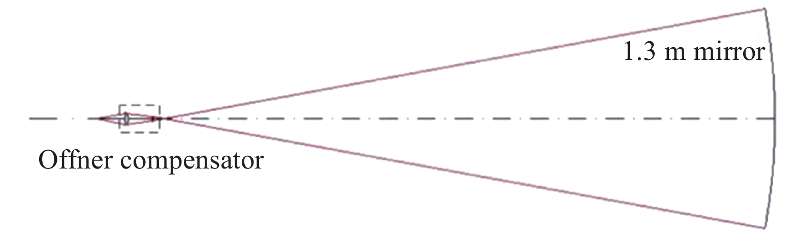
      Figure 3.  1.3 m mirror detection optical path

      通过上述分析,可知在大口径反射镜的零重力面形W0g提取过程中存在以下难点:

      (1) 反射镜组件的装配误差,主要是胶黏剂固化收缩应力与重力作用混叠,造成重力误差中的像散等非旋转对称像差提取困难;

      (2) 零位补偿检验光路的间距调整误差,造成重力误差中的Power、球差等旋转对称像差测试精度不足。

      针对造成不同类型像差测试精度不足的原因,提出了翻转与卸载相结合、实测全部重力误差的测试方案。

    • 针对非旋转对称像差和旋转对称像差的不同特点,采用不同的方法来获取其精确的测试数据,从而实现对全部重力误差的准确评估:通过变换反射镜组件的方位进行像散等非旋转对称像差的测试,分离重力误差与装配误差;在一定精度的重力卸载下进行对比测试,获取球差等旋转对称像差,避免检测光路对旋转对称像差测试精度的影响。

      重力作用下的反射镜面形W为:W=W1+W2+W1g。因为各像差具有正交性,W1g又分解为因重力引起的非旋转对称像差(三叶像差等)和旋转对称像差(Power、球差等):W1g=Woff-axis+Won-axis

    • 通过变换反射镜组件的方位进行重力变形测量。任何结构体在分别承受大小相同、方向完全相反的力场时,其变形量应该是大小一致,方向相反。重力翻转测试方法正是基于这一理论进行推演,分别测试光学组件在光轴竖直向上和光轴竖直向下两个状态下的面形变化,并通过两个状态的数据叠加来获得无重力影响的光学测试面形结果[14-15]。Bipod结构是装配关系简单、力学边界条件明确的准静定支撑,因此在进行翻转测试的过程中,因翻转工装引入的误差对测试结果影响比较轻微,光学组件光轴竖直向上和向下的两个状态相比,其重力造成的面形误差在数值上相等,在相位上相反,而加工残留误差和装配误差不变。因此,当光学组件光轴竖直向上时,其面形Wu为:

      当光轴竖直向下时,其面形Wd为:

      剔除Won-axis,此时光轴竖直向上和向下的面形${{W}_{{\rm{u}}}'}$${W}_{{\rm{d}}}'$分别为:${{W}_{{\rm{u}}}' }$=W1+W2+Woff-axis${W}_{{\rm{d}}}'$=W1+W2Woff-axis。因此,重力误差的非旋转对称像差为:

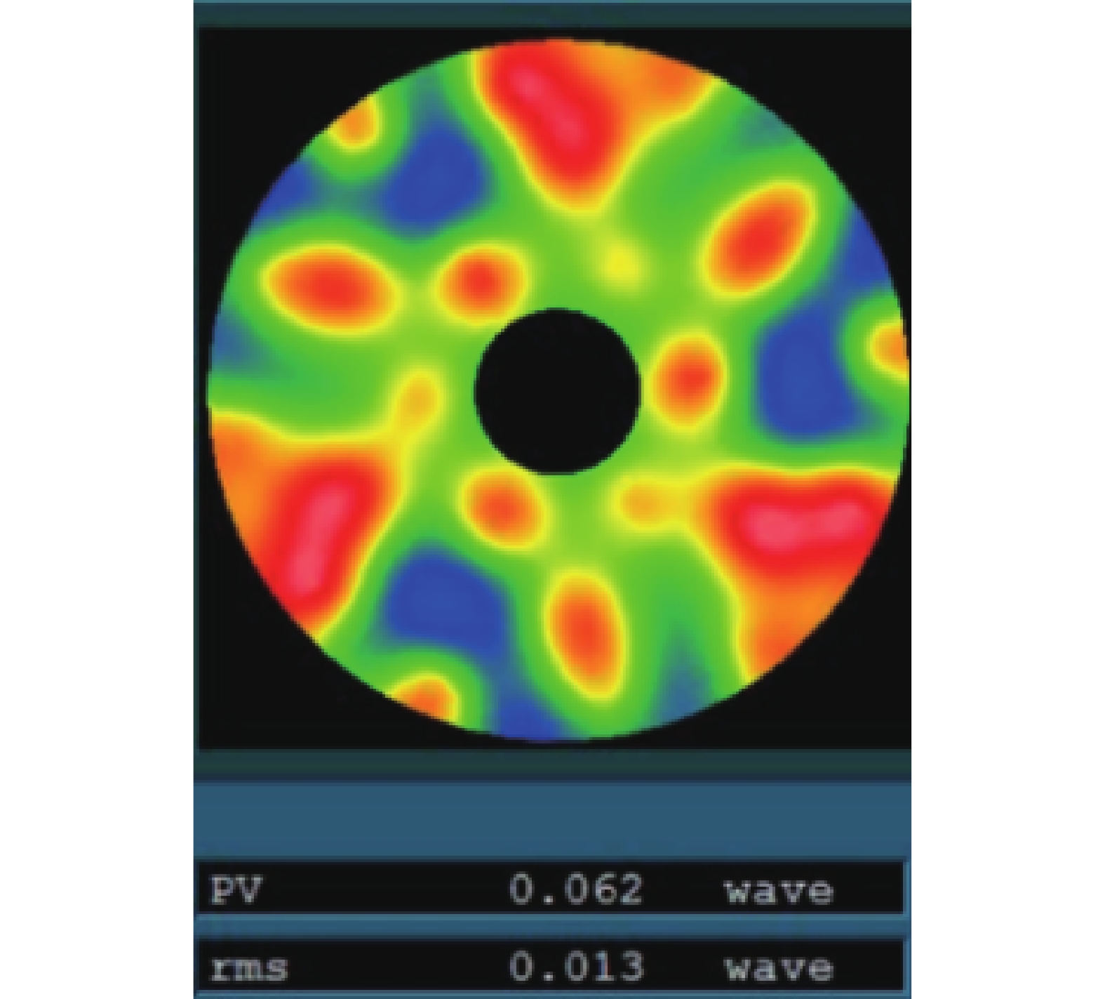
    • 通过测试反射镜组件进行重力卸载与不卸载的Power、球差等旋转对称像差,计算其变化量,从而得到因重力引起的旋转对称像差。与大口径反射镜加工阶段的重力卸载相比,组件级的重力卸载只需要对检测精度不足的特定像差进行卸载,不要求对全部重力误差进行卸载,设计和装调的难度都会大大降低,从而更加容易实现较高的精度。针对1.3 m口径、采用背部6点Bipod支撑的反射镜组件,设计18点的重力卸载装置,即可将其面形卸载至0.013λ,其中Power、球差的残余值为0.002λ和0.003λ。卸载后面形残差如图4所示。与加工阶段使用的200点卸载装置相比,点数大幅度降低。同时,卸载力的加载形式由气缸加载改为杠杆加载,大大简化了复杂程度,能够在有限空间内进行布局。

      Figure 4.  Surface figure residual of 18 points unloading

      调整好检测光路,先测试无卸载状态下的反射镜面形,仅保留旋转对称像差Won-axis1,再行安装卸载装置,调整各卸载点的位置与卸载力。保持检测光路不变,测试此时的反射镜面形,此时面形包含了卸载引起的非旋转对称像差,予以剔除,仅保留旋转对称像差Won-axis2。卸载前后镜体刚体位移造成的旋转对称像差为Won-axis。则重力引起的旋转对称像差为:

      大口径反射镜组件的重力误差和零重力面形分别为:

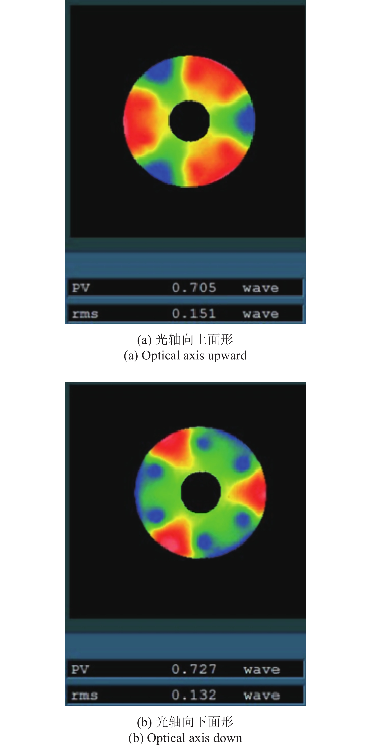
    • 运用上述技术对1.3 m口径反射镜组件进行了重力误差测试。首先进行重力翻转测试,光轴竖直向上和竖直向下的面形测试结果(去除Power与球差)如图5所示。根据公式(3),三叶像差为−0.405λ

      Figure 5.  Test results of gravity turnover

      再进行卸载前后的对比测试,有卸载和无卸载的面形如图6所示。

      使用三坐标测量卸载前后主镜的位移情况,在光轴方向位移为0.02 mm。在检测光路中,其刚体位移引起的Power、球差变化分别为−0.012λ和−0.003λ。根据公式(4),Power和球差分别为−0.189λ和−0.122λ

      重力误差和0 g面形分别如图7(a)和图7(b)所示。

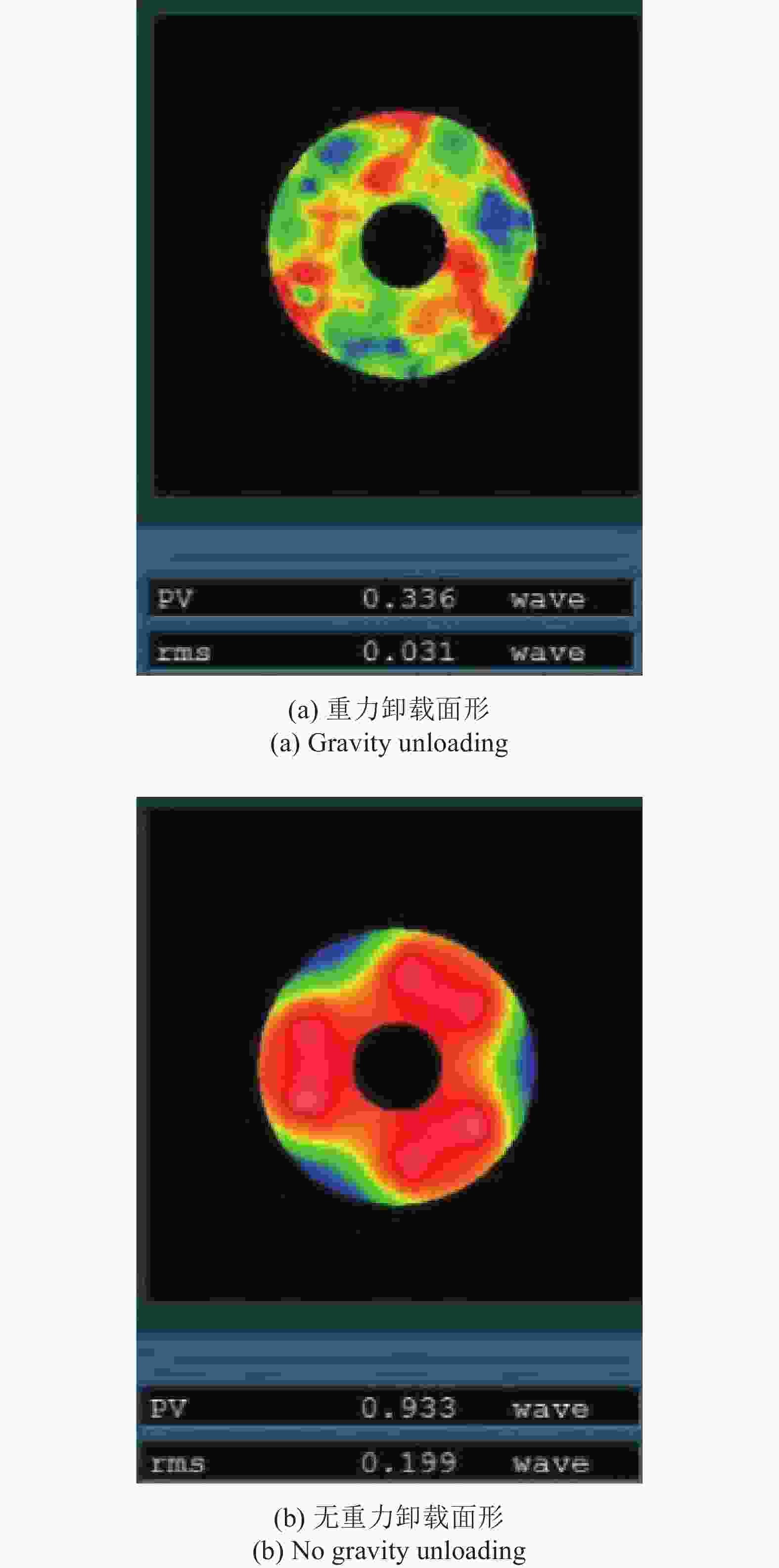
      Figure 6.  Test results with and without unloading

      Figure 7.  Gravity error (a) and 0 g surface figure (b)

    • 通过变换方位对重力误差与装配误差进行了剥离,通过卸载对比测试提高了旋转对称像差的精度。成功获取了1.3m口径反射镜的重力误差与零重力面形。试验结果证明该项测试技术理论正确,工程实现性更好。该研究成果可为类似口径的空间相机的在轨像质评价提供一定的借鉴。

Reference (15)

Catalog

    /

    DownLoad:  Full-Size Img  PowerPoint
    Return
    Return