


-
随着电力系统容量与绝缘等级的提高,对电流传感器的暂态响应性能的要求越来越高。基于电磁感应的传统电流互感器,已经呈现出许多不可克服的问题,不能满足新一代电力系统的要求[1]。采用数字闭环控制的光纤电流传感器具有绝缘性好、动态范围大、频带宽等特点,受到了越来越广泛的关注[2]。
频率响应与阶跃响应是评价电流传感器暂态性能的重要指标,对于继电保护控制、故障录波等应用领域具有较高的研究价值[3]。在工程应用中,通常采用高功率电流信号发生器产生测试波形实现对频率响应与阶跃响应的测试。但由于其测试系统复杂,并且产生的电流信号较小,无法准确评估电流传感器的动态特性[4-5]。为了分析光纤电流传感器的闭环控制效果,评价光纤电流传感器的动态响应特性,参考文献[6-10]通过建立光纤电流传感器的数学模型,对光纤电流传感器的动态特性进行了理论仿真分析。但考虑到系统设计的电路噪声、A/D 转换延时、数字滤波算法等都会对暂态特性产生影响,因此需要一种对现有系统暂态响应进行测试的方法。
文中介绍了一种通过在光纤电流传感器光路上添加相位调制激励的方法,模拟外界电流信息,利用光纤电流传感器的信号处理算法,解调出光纤电流传感器对外界电流信息的响应曲线,从而实现对光纤电流传感器频率响应与阶跃响应的测试。通过试验对比,该激励测试方法与试验结果一致,并且无需搭建测试设备,可以实现光纤电流传感器对暂态电流测量的性能评估,是一种简单、适用、有效的光纤电流传感器暂态测试方法。
-
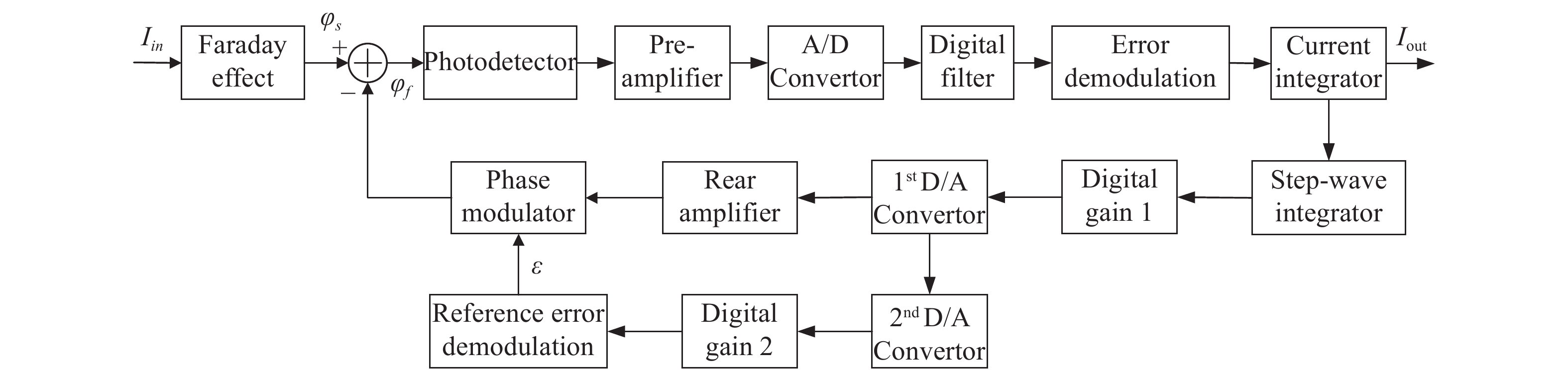
光纤电流传感器是通过检测两束偏振光在Faraday磁场效应下的干涉光强来测量电流,其结构框图如图1所示[11]。

Figure 1. Diagram of fiber optic current sensor structure
超辐射发光二极管(SLD)输出的光通过2×2耦合器后分为两束光,其中一路光经过起偏器后输出为线偏振光,起偏器与相位调制器的保偏光纤采用45°熔接,从而形成两束正交等分的线偏振光沿保偏光纤的快轴和慢轴传输至相位调制器和光纤延迟线。两束线偏振光经过λ/4波片后转换为左旋圆偏振光和右旋圆偏振光,进入传感光纤。传感光纤缠绕在被测电流周围,用来敏感被测电流产生的磁场。根据法拉第磁光效应原理,传感光纤中沿着磁场传输的两束圆偏振光受到磁场影响后传输速率发生变化,从而产生法拉第相位差。两束带有相位差的圆偏振光经光纤端面反射镜、λ/4波片后恢复为线偏振光,在偏振器处发生干涉[12]。干涉光强的表达式为:
式中:V为Verdet常数;I为待测电流;N为传感光纤的线圈匝数。
干涉光通过耦合器后进入探测器转换为电信号,经信号处理电路调制与解调后输出测量电流值。为提升光纤电流传感器的电流测量范围,并且保证测量范围内的测量线性度,通常采用数字闭环方案,利用相位调制器的电光效应实现对法拉第相位差的方波调制与闭环反馈[13]。
-
根据光纤电流传感器闭环工作原理,可以建立光纤电流传感器的数字控制模型,如图2所示。光纤电流传感器系统利用采样数字量进行数字处理,因此该系统可以看作离散时间系统,如图3所示。图中,Ks为法拉第效应的比例系数; Kpd为光电探测器的光电转换系数;K1为A/D转换器前端放大器的放大倍数;KAD为A/D转换器的模数转换系数;K2为过采样积分的累加倍数;Kr为电流闭环误差的解调系数,可以近似为1;而电流积分器和阶梯波积分器作为离散信号的累加器,可以等效为1/(1−z−1);KG1为位数变化引起的数字增益;KM为相位调制器的调制系数,图中通过第二闭环回路调节第一路D/A转换器的转换系数,其中KDA1为第一路D/A转换器的转换系数;Kε为相位调制误差的解调系数;而相位调制误差积分器是一个累加器,可以等效为1/(1−z−1);φ(z)为调制相位的z域表示[14]。

Figure 2. Data control model of fiber optic current sensor

Figure 3. Mathematical model of optical fiber current sensor
由图3可知:
因此,光纤电流传感器的传递函数为:
式中:KA=KpdK1KADK2;KB=KMKDA1KG1。
-
根据上述光纤电流传感器的工作原理可以看出,外界电流产生的磁场会引起光纤电流传感器的两束偏振光的相位差,而相位调制器也可以通过电场产生两束光的相位差,因此可以利用相位调制器产生相位调制激励,模拟外界电流产生的相位差,从而实现对光纤电流传感器的动态性能测试。
利用相位调制激励的系统传递函数框图如图4所示。

Figure 4. Mathematical model of optical fiber current sensor with test excitation
图中,P(Z)为软件产生的相位调制激励。
由公式(3)与公式(5)可以得到:
由公式(6)可以看出,电流产生的相位差与通过相位调制器产生的相位调制激励符号相反,数值存在比例关系
$ {K_s}/{K_B} $ 。由于在确定系统中,Ks与KB为固定值,激励相位差与Faraday相位差为线性比例关系,因此可以通过对相位调制器添加相位调制激励的方法实现对光纤电流传感器的动态性能测试。由光纤电流传感器的工作原理可以知道,待测电流产生的法拉第相位差为φ=4 VNI,相位调制器的相位为φm=Km×V,其中Km为相位调制系数,Km= 2π/ V2π,V2π为相位调制器的半波电压。在LLG−1100光纤电流传感器中,使用了一路16位的DA输出调制信号,因此输出电压为V=D/65 536×Vref,其中,Vref为DA的基准电压,D为激励数字量。因此可以得到:
因此,得到电流I与激励数字量之间的对应关系:
式中:Dλ为相位调制器的半波电压数字量。
-
阶跃响应是指电流突然发生变化时,电流传感器的输出响应过程。在测试过程中,通常对电流传感器施加方波波形的电流信号,考察电流传感器在正向跳变与负向跳变的响应过程。由于光纤电流传感器的光路的渡越时间很短,通常为几个μs量级,因此可以使用相位调制器产生的相位调制激励准确体现电流传感器的响应曲线。
根据闭环光纤电流传感器工作原理,相位调制产生的相位差为:
式中:V(t)为施加在相位调制器上的电压信号;T为光纤电流传感器的渡越时间。 待测电流产生的法拉第相位差为:
因此,要实现相位调制激励,相位调制信号应满足:
当待测电流为阶跃信号时,则:
式中:Tm为阶跃信号的持续时间(假设阶跃信号为方波信号)。那么,实现阶跃信号的相位调制信号应满足:
由上式可以看出,当进行阶跃响应测试时,相位调制激励为斜率反转的线性电压。考虑到相位调制器调制电压无法无限升高,根据光纤电流传感器2π复位原理,施加的电压信号进行2π复位可以保证调制相位的周期性。
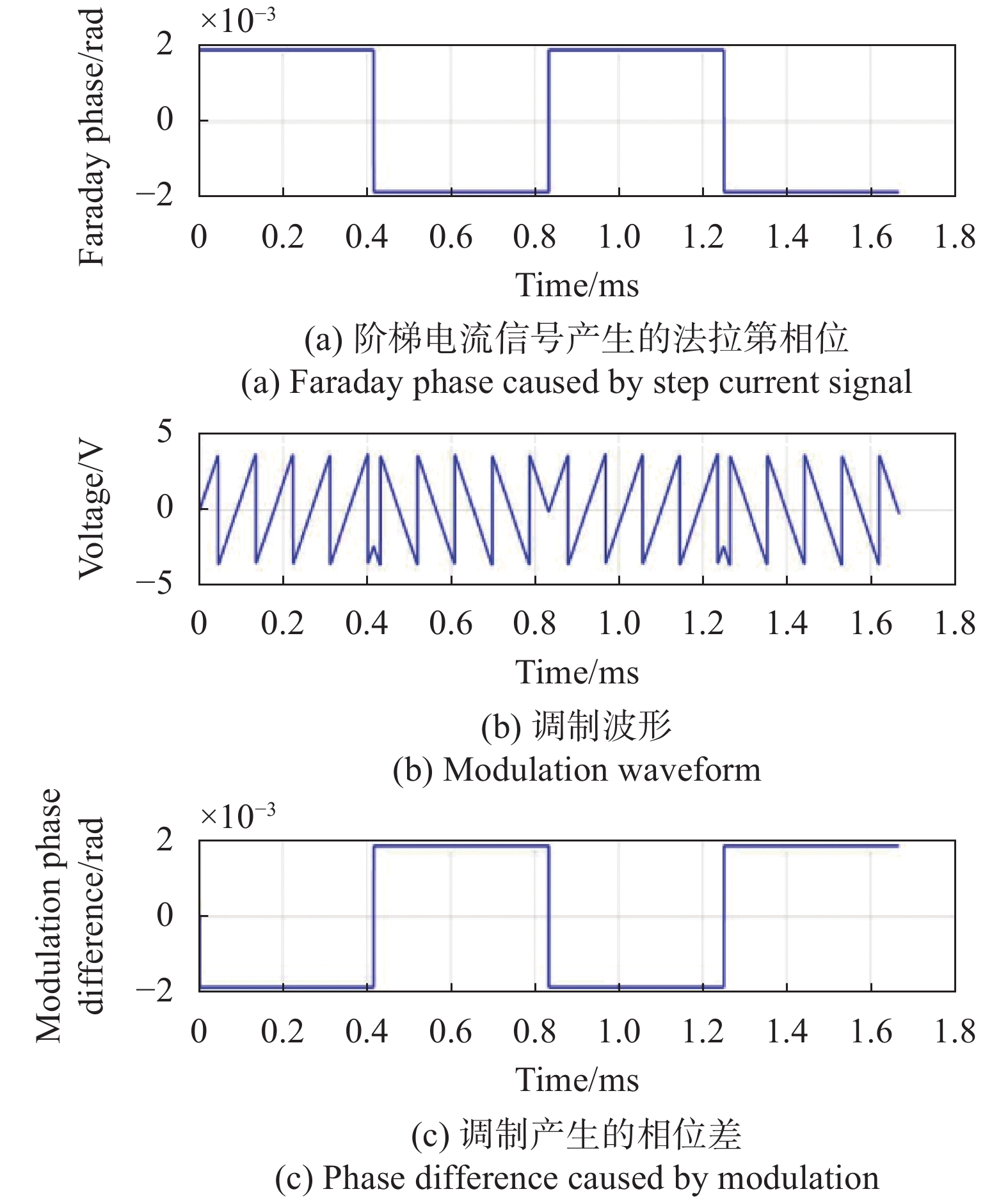
在光纤电流传感器中,为产生电流阶跃激励信号,相位调制器上添加的相位调制激励电压如图5所示。

Figure 5. Step response modulation excitation of FOCS
由图可以看出,当电流为固定值时,需要在相位调制器上施加一个固定台阶高度的阶梯波相位调制激励,阶梯波复位方式与闭环复位方式一致。施加相位调制激励产生的两束光相位差与电流产生的相位差符号相反,与系统模型一致。
-
正弦响应是指对电流传感器施加一定频率的正弦电流时,电流传感器的响应曲线。通过测试电流传感器在不同频率下的幅值衰减,可以测试电流传感器的带宽。
当待测电流为正弦信号时,则:
式中:f0为待测电流的频率。根据公式(13),施加在相位调制器上的激励信号为:
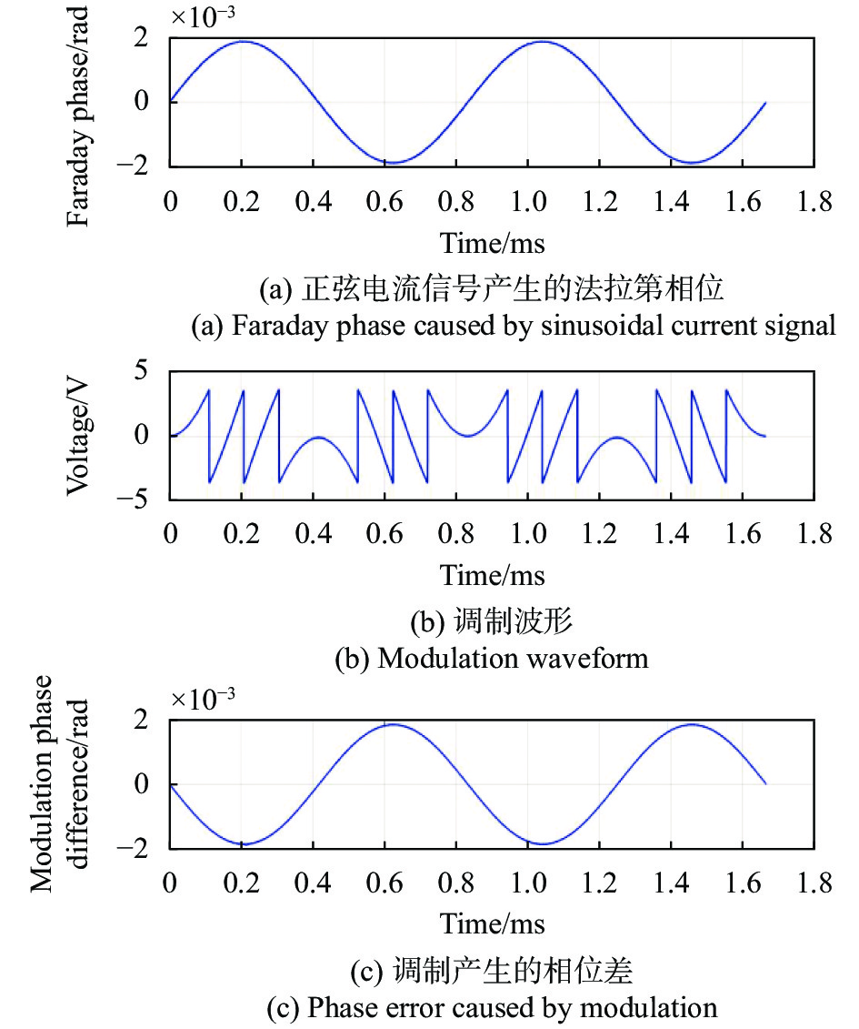
由公式(15)可以看出,当待测电流为正弦信号时,相位调制器上的调制激励信号为相应频率的余弦信号。同样的,对激励信号进行2π复位可以保证调制相位的周期性,相位调制器上添加的相位调制激励电压如图6所示。

Figure 6. Sinusoidal modulation excitation of FOCS
由图可以看出,施加相位调制激励产生的相位差与电流产生的相位差符号相反,与系统模型一致。
-
为验证相位调制激励与实际试验结果的一致性,使用西安中科智晶电力科技有限公司的LLG−1100光纤电流传感器按上述两种测试方法进行对比试验。LLG−1100光纤电流传感器的光纤匝数N=10,半波电压Dλ=32768,维尔德常量V=0.768×10⁻⁶ rad/A,解调周期为1.51 μs,输出频率为10 kHz,每个采样点的间隔为100 μs。高功率信号发生器可以产生10 A电流,在试验室中采用等安匝原理,将母线围绕光纤电流传感器传感头缠绕10圈,等效产生100 A的测试电流,线性度可以达到1 ppm (1ppm=10−6)[15]。通过设置信号发生器输出阶跃响应波形及不同频率的正弦波形,对比LLG−1100光纤电流传感器的试验结果与仿真结果。
-
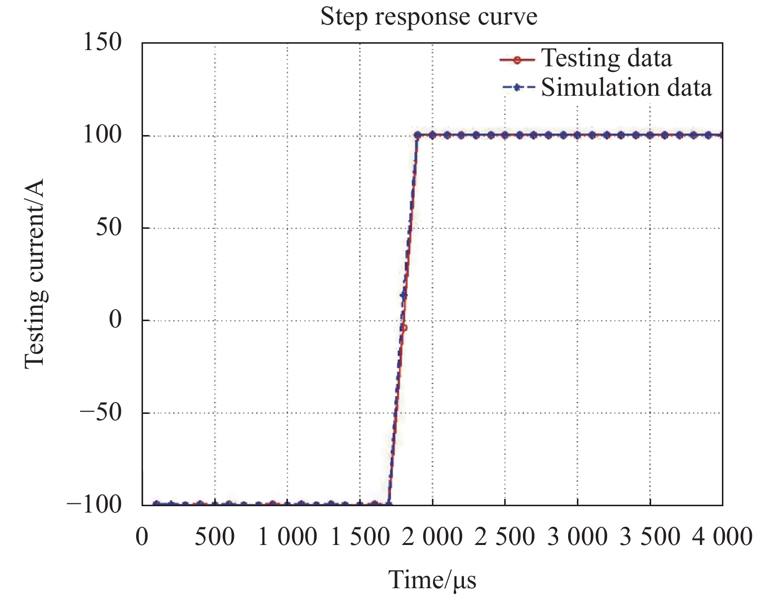
阶跃响应模拟±100 A电流下光纤电流传感器的输出响应,通过公式(8)计算得到阶梯波相位调制激励的固定台阶高度为16,在光纤电流传感器闭环控制算法中添加阶梯波相位调制激励,得到阶跃响应的输出如图7所示。
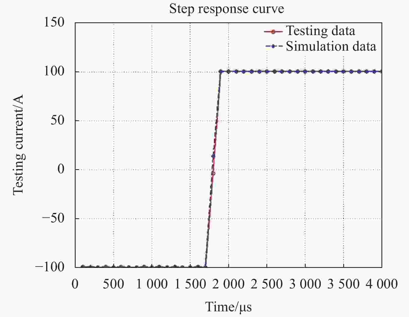
Figure 7. Step response simulation and test curve of fiber optic current sensor
LLG−1100光纤电流传感器的阶跃响应试验数据与仿真数据如表1所示。
Data Overshoot percent Rise time/μs Experimental data 0% 100-200 Simulation data 0% 100-200 Table 1. Comparison of step response simulation data
由于采样周期限制,每个采样点的间隔为100 μs,由表1可以看出,采用激励的方式得到的仿真数据与试验数据一致。可以反映光纤电流传感器的阶跃响应特性。
-
频率响应模拟频率范围50 Hz~2 kHz,额定电流100 A光纤电流传感器的输出响应,通过公式(8)计算得到阶梯波相位调制激励的幅值为16,在光纤电流传感器闭环控制算法中添加阶梯波相位调制激励,通过改变激励频率来得到不同频率下的输出响应。利用公式(16)~(17)分别计算添加激励仿真及等安匝测试的幅值误差:
式中: I0为设置电流值;I1为添加激励仿真的电流输出值;I2为等安匝测试电流输出值。
频率响应曲线如图8所示。由表2可以看出,采用相位调制激励的仿真数据与试验数据最大偏差为0.12%,满足0.5级光纤电流传感器的频率响应要求,可以反映光纤电流传感器的频率响应特性。
Frequency/Hz Experimental data error Simulation data error 50 −0.03% 0.01% 150 0.06% −0.05% 600 −0.06% −0.06% 800 −0.13% −0.11% 1200 −0.39% −0.27% 1600 −0.76% −0.73% 1800 −1.05% −1.08% 2000 −1.55% −1.52% Table 2. Experimental and simulation data of frequency response

Figure 8. Simulation and testing curves of amplitude error-frequency characteristic for LLG−1100
-
数字闭环光纤电流传感器具有测量范围大、动态特性好的特点,非常适合大容量电力系统中使用。阶跃响应与频率响应是评判光纤电流传感器暂态性能的关键指标,但传统测试方法具有一定的局限性。文中提供了一种通过利用相位调制器在光路上添加相位调制激励的方法,实现了对电流的阶跃响应与频率响应测试。并对激励原理进行了数学建模与计算,计算结果表明该测试激励与实际测试结果一致,具备等效性。测试结果表明通过添加相位调制激励的方法可以实现对光纤电流传感器的阶跃响应与频率响应的测量,对光纤电流传感器的暂态响应测试具有指导意义。
Simulation research of the transient characteristics of a digital closed-loop fiber optic current sensor
doi: 10.3788/IRLA20210615
- Received Date: 2022-01-20
- Rev Recd Date: 2022-03-15
- Publish Date: 2022-08-05
-
Key words:
- digital closed-loop fiber optic current sensor /
- frequency response /
- step response /
- modulation excitation
Abstract: Transient characteristics of digital closed-loop fiber optic current sensors (FOCSs) include the frequency response and step response which are important indexs in the industrial areas such as power system relay protection and fault recording. In engineering applications, due to the complexity of the test system and the poor accuracy of a small current signal, it is not conducive to evaluating the transient characteristics of an FOCS in a traditional way. According to the closed-loop control mechanism of a digital closed-loop optical fiber current sensor, a new method of adding phase modulation excitation to the feedback loop of a digital closed-loop FOCS was researched. First, the phase modulation principle of the digital closed-loop of FOCS was analysed, and a mathematical model was established to calculate and verify the equivalence of the phase modulation excitation; Second, based on the closed-loop control algorithm of the FOCS, the frequency response and step response modulation excitation generation method were proposed; Finally, use the existing digital closed-loop FOCS product platform was used to complete the simulation and test of frequency response and step response. The results show that the maximum error between simulation data and test data is 0.12%. The modulation excitation method can realize different current simulation tests of frequency response and step response on the existing hardware platform without building a complex test system.


 DownLoad: