


-
太赫兹(THz)波是指频率在0.1~10 THz范围内的电磁波[1]。THz波具有透射能力强、频率范围宽、信噪比高[2]、单光子能量低[3]等特点,近年来被广泛运用到物体成像[4]、宇宙探测[5]、分子探测[6]、移动通信[7]等各种领域。
由于很多生物大分子及DNA的旋转及振动能级处于THz波段,所以可以利用THz辐射来对病变生物体及病变标志物进行探测。目前大量研究表明,可以在共面波导[8](CPW)上制作谐振结构,病变生物体及病变标志物和正常生物体通过谐振结构会导致THz波产生不同的振幅、波形和时延。通过对生物分子THz吸收谱的研究得到其振动及构象变化信息,可以对相关疾病做出早期诊断。目前由于水汽对THz波的强吸收及制造工艺等原因,引导THz传输到共面波导主要依赖天线和矩形波导[9]。相较于天线传输,矩形波导结构简单、机械强度更大。矩形波导与共面波导在直接馈电的情况下,矩形波导中电磁波主要以TE模、TM模传输,而共面波导传输TEM模,因此存在动量和模式不匹配的问题。在这种情况下,矩形波导到共面波导的转换[10]成为近年来研究的热点。实现低插入损耗且可用于现有电路和芯片封装的转换结构具有重要的研究意义和应用潜力。
目前的转换结构主要基于E面探针、线键合探针、贴片天线、金属脊和缝隙耦合设计,且已经取得许多研究成果。2016年,Dong Yunfeng[11-14]等人首次使用线键合实现U波段矩形波导到共面波导转换;2018年,分别利用线键合探针和贴片天线在110~166.3 GHz、118.8~161 GHz实现插入损耗为2 dB的转换结构;2019年,利用金属脊结构在122.5~156.5 GHz实现插入损耗小于3 dB的转换结构;2020年,Tang Wenxuan[15]等人利用金属脊结构在12~18 GHz实现矩形波导到表面等离子体的过渡; 2021年,H. Aliakbarian[16]在91.2~113.2 GHz实现插入损耗为1.8 dB的转换。
虽然目前转换结构的研究工作被大量报道,但关于矩形波导到共面波导转换结构的设计主要集中在0~80 GHz的低频段或低于0.17 THz的THz频段且带宽较窄,无法满足0.2 THz以上的使用需求。鉴于此,文中利用脊波导进行阻抗匹配及电磁场模式转换设计了一种过渡结构。结果表明,通过三阶金属脊逐级过渡,可以使电磁波在240~350 GHz全频段实现插入损耗小于3 dB的转换。
-
脊波导以阻抗渐变的形式实现矩形波导到共面波导的转换。矩形波导电磁场传输特性由波阻抗[10]ZTE描述。
矩形波导中传输TE10模时的波阻抗可表示为:
式中:
$ {\eta }_{0}=377\;\mathrm{ }\mathrm{ }\mathrm{ }\mathrm{ }\mathrm {\Omega } $ 为自由空间波阻抗;$ {\lambda }_{0} $ 为中心频率波长;a为矩形波导宽边尺寸。为了解决波导间的匹配及转换问题,Southworth [17]提出电压功率定义的特征阻抗ZOVP作为矩形波导等效特性阻抗。
该设计矩形波导在WR-3.4标准矩形波导的基础上进行重新设计,其中a =711.2 μm、b= 355.6 μm,中心频率f0=295 GHz,
$ {\lambda }_{0} $ =1.02 mm,$ {Z}_{OVP}={Z}_{{TE}_{10}}= $ 539$ \mathrm{\Omega } $ 。要保证与共面波导50$ \mathrm{\Omega } $ 的特性阻抗匹配,必须在矩形波导与共面波导之间加入适当的阻抗变换器。该设计采取阶梯脊形转换结构,根据切比雪夫阻抗变换器[18]设计原理,转换结构阻抗由539~50
$ \mathrm{\Omega } $ 阻抗变换比为$ R=0.09 $ 。最大驻波系数$ \;{\rho }_{max} $ 设为1.1。可求出坐标变换待定系数h、p及脊波导最小阶数n。故最小阶数为3,考虑到计算误差及制造工艺复杂度本设计选取阶梯脊数为3。相较于基于渐变线阻抗变换器[10]设计的三角形过渡结构,脊波导可以避免电路谐振问题,适用于宽带电路且加工容错率更高、结构刚度更强易于保存运输。
图1为脊波导截面图。a、b分别为矩形波导宽边和窄边,阶梯脊厚度为th,脊到底壁距离为d。d值较小时,电磁场能量集中于脊下,等效阻抗较低,可与共面波导匹配连接;当d增大时,等效阻抗增加可连接矩形波导。通过改变阶梯脊的高度及宽度可以将矩形波导的特性阻抗变换到与共面波导匹配的阻抗。

Figure 1. Section of metal ladder ridge
-
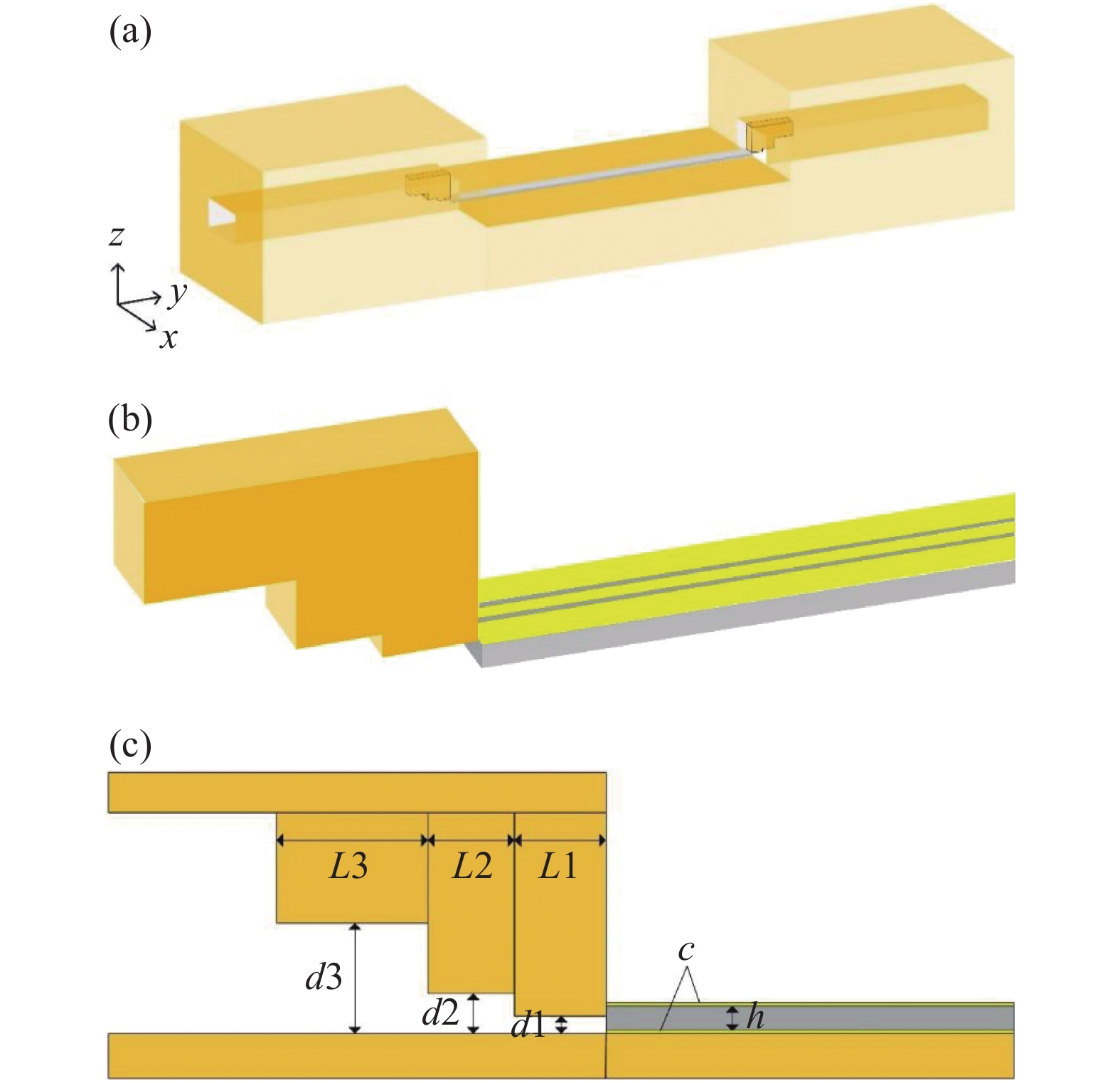
文中设计的矩形波导到共面波导转换结构由矩形波导和脊波导两部分组成,转换结构结合共面波导示意图如图2(a)所示,转换结构细节图、几何参数图如图2(b)、(c)所示。矩形波导材料为铜,其内截面尺寸为711.2 μm×355.6 μm。共面波导由h=40 μm石英基底(ε=3.75,μ=1)背敷接地板和表面刻蚀的信号线及两条地线组成,其中接地板、信号线和地线材料均为金且厚度为c=0.4 μm,信号线宽为36 μm,地线宽为78 μm,信号线与地线间隙为4 μm,共面波导长为4 mm。转换结构中脊波导与矩形波导相连,由三段金属脊构成,脊的长度为Li(i=1,2,3),距下壁高度为di(i=1,2,3),厚度为th。

Figure 2. Rectangular waveguide-to-coplanar waveguide conversion model. (a) Conversion structure diagram of the overall model; (b) Detail diagram of metal ridge of conversion structure; (c) Partial geometric parameters of metal ridges combined with coplanar waveguides
文中使用有限积分软件(CST)进行模拟仿真。THz波以TE模由矩形波导一端入射经过转换结构转换为TEM模后进入共面波导,在共面波导另一端加相同的转换结构并检测传输系数以表征该结构的转换性能。通过仿真对转换结构金属脊的各个参数进行调整,确定最优结构。
-
脊波导第一脊到波导底壁距离d1直接影响转换结构的传输性能。对d1
分别取25、35、45、55 μm进行仿真分析。其余结构参数设定如下:第一脊长度L1=145 μm,第二脊长度L2=140 μm,第三脊长度L3=240 μm,第二脊距底壁高度d2=70 μm,第三脊距底壁高度d3=180 μm,脊厚度th=140 μm。 在240~350 GHz频率内,转换结构的仿真结果(S21参数)如图3所示。当d1超过45 μm后传输系数明显下降;d1=25 μm时,高频段传输系数下降;当d1=35 μm时,转换结构会获得较好传输效率和工作带宽。已知共面波导上层金膜距波导底壁高度为40.8 μm,故第一脊要略低于共面波导金膜。对仿真结果进行对比后,文中选取d1为35 μm。
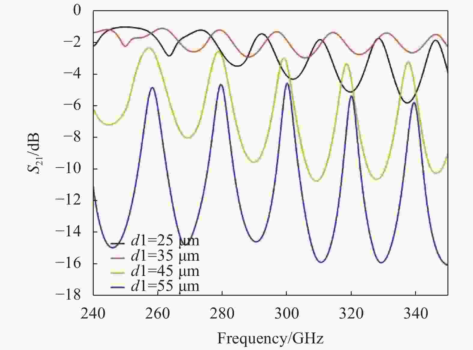
Figure 3. The simulated transmission coefficient of the conversion structure at different first ridge height d1
通过d2、d3进行仿真,结果表明d2在50~70 μm、d3在180~260 μm范围内可使结构获取高传输效率。d2小于70 μm时在低频段损耗较大,为实现长工作带宽本设计选取d2= 70 μm。d3大于180 μm会减小中频段传输损耗但在通频带两端损耗会有增加,故d3
取180 μm。 -
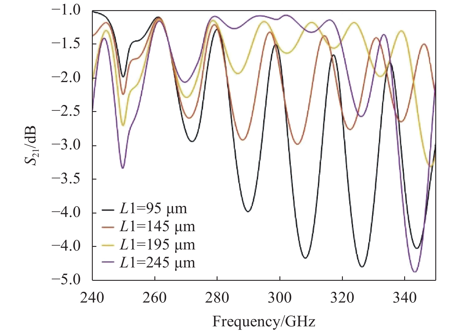
在设定d1为35 μm并保持其他结构参数不变的情况下,改变第一脊的长度L1的数值(分别为95、145、195、245 μm)进行仿真,仿真结果如图4所示。
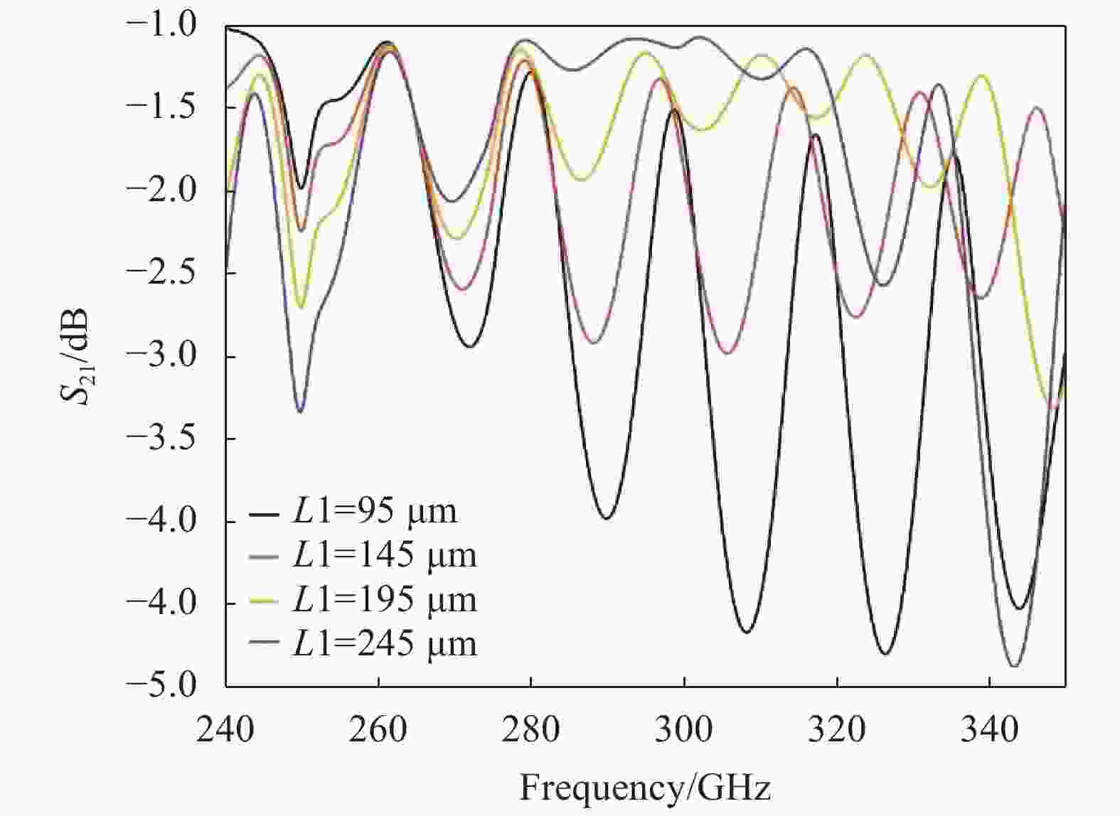
Figure 4. The simulated transmission coefficient of the conversion structure at different first ridge length L1
从图中可以看出随着L1逐渐增大,转换结构的传输系数逐渐减小,当L1=245 μm时在超过320 GHz的高频段传输系数明显减小,L1=195 μm和L1=145 μm时转换结构均可达到高传输效率,但L1=145 μm 在全频段传输性能更稳定可用带宽更长,文中选取L1=145 μm进行进一步研究。
对L2、L3进行仿真分析, L2取140 μm、L3在180~240 μm范围内不影响结构的高传输效率。L2过小会增加高频段损耗、过大增加低频段损耗,L3取240 μm在高频段损耗更小。
-
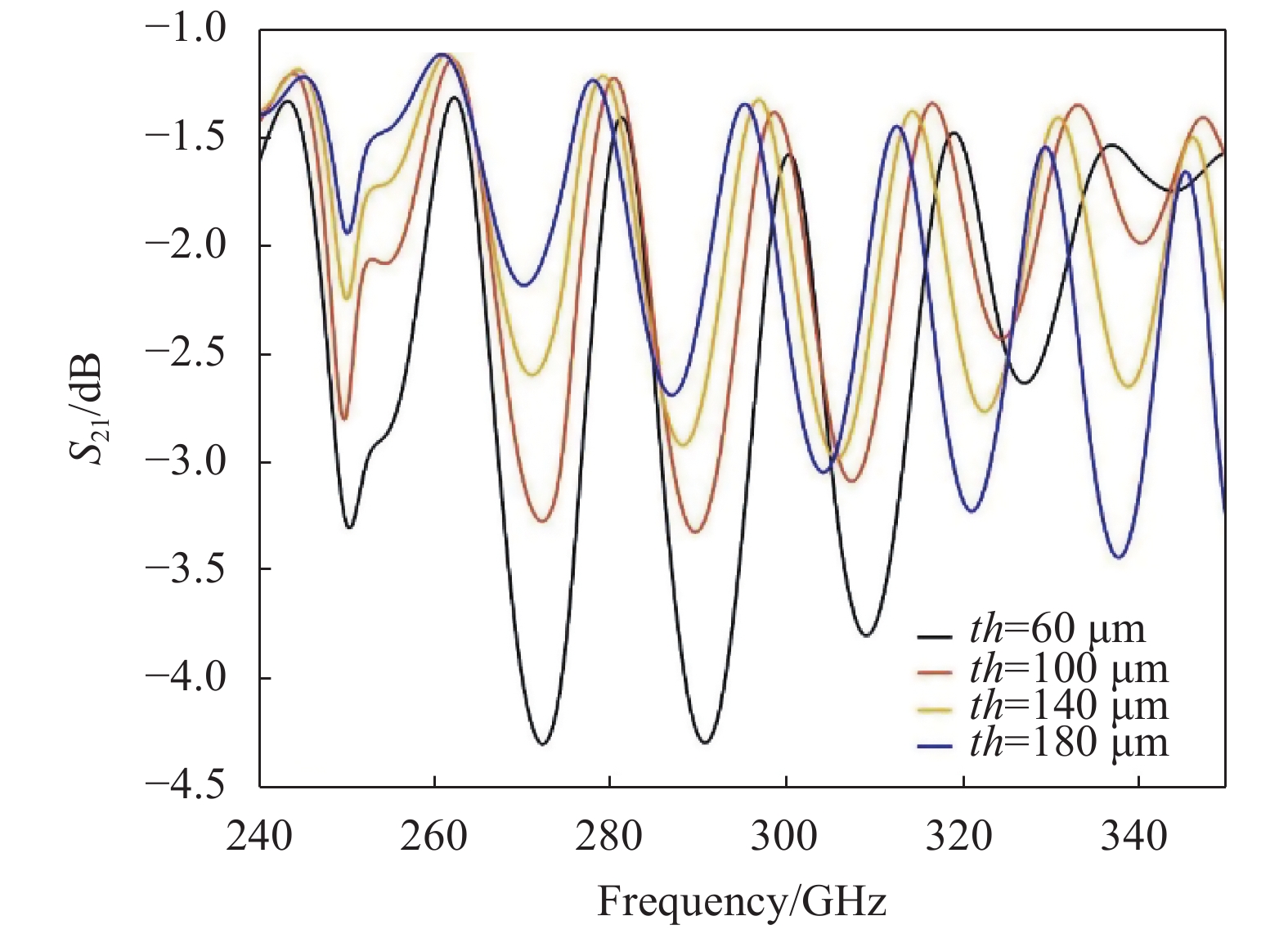
阶梯脊厚度th在整体转换效果中也起到了重要作用,保持其余结构参数不变,取 th分别为60、100、140、180 μm进行参数扫描,对应的转换结构传输系数如图5所示。
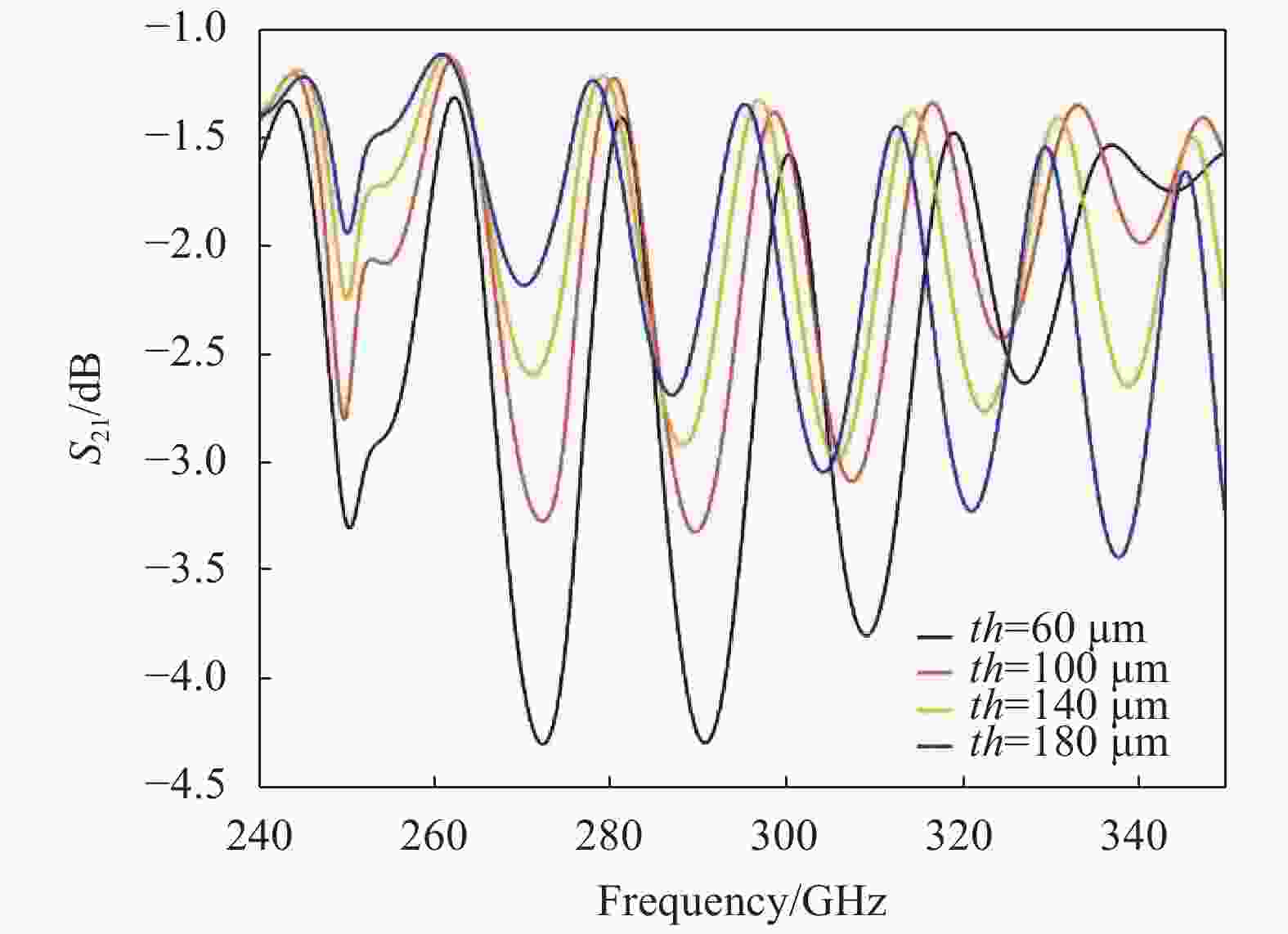
Figure 5. The simulated transmission coefficient of the conversion structure at different step ridge thickness th
分析图5可以得出,随着阶梯脊厚度的增加转换结构在低频传输效率提高,高频传输效率下降。文中选取th =140 μm进行以获取全频段的高传输效率。
-
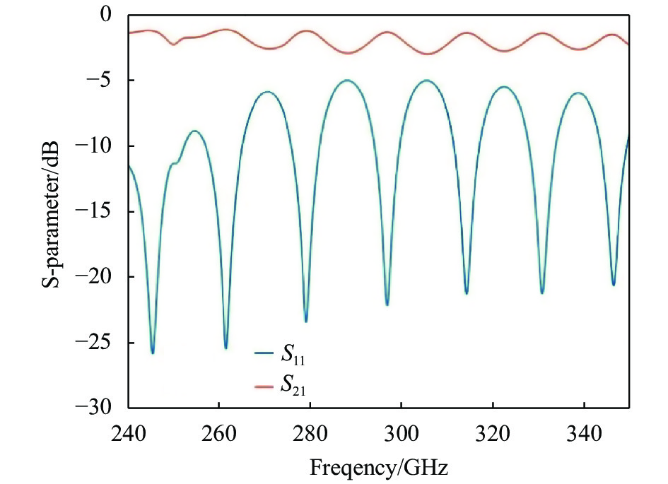
综上,得到THz矩形波导到共面波导转换结构的具体参数如表1所示,由此仿真计算得到转换结构的S参数如图6所示。
Parameter c h L1 L2 L3 d1 d2 d3 th Value/μm 0.4 40 145 140 240 35 70 180 140 Table 1. Conversion structural parameters of terahertz rectangular waveguide to coplanar waveguide

Figure 6. Simulated S-parameters of the transformation structure
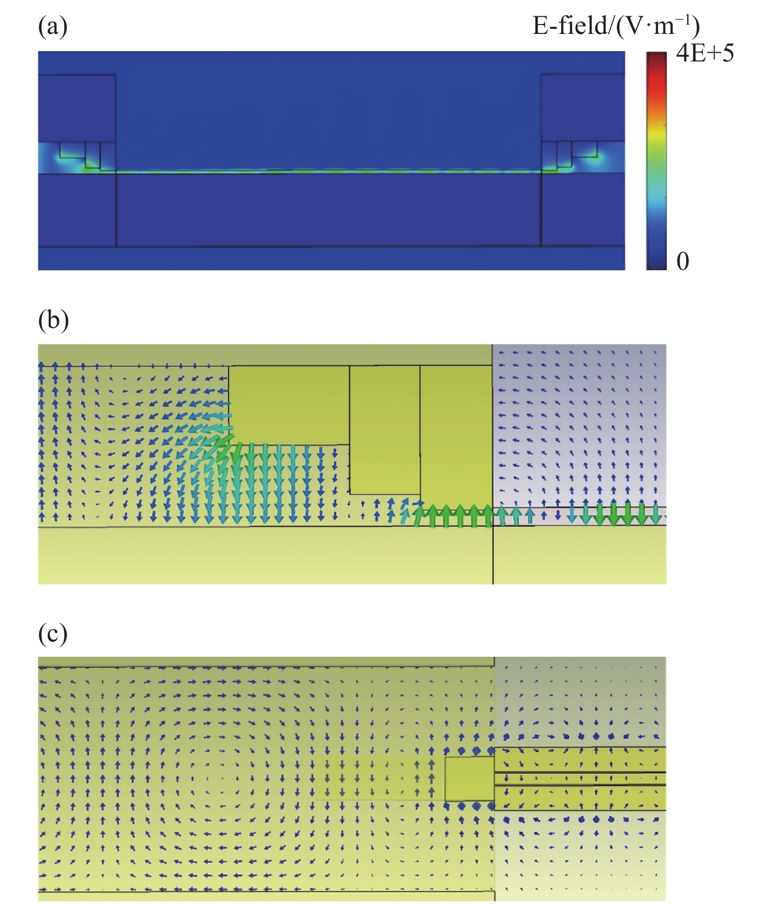
结果表明,该转换结构在240~350 GHz的频带上传输系数高于−3 dB。图7为305 GHz时矩形波导到共面波导的模式转换图,通过图7(a)的电场幅值图可以直观反映电磁波通过转换结构金属脊耦合到共面波导的过程。图7(b)、(c)为电/磁场矢量图,在矩形波导中,可以观察到TE模的电磁场分布,在阶梯脊右侧,只有忽略不计的纵向电磁场分量,表明了TEM模的形成。
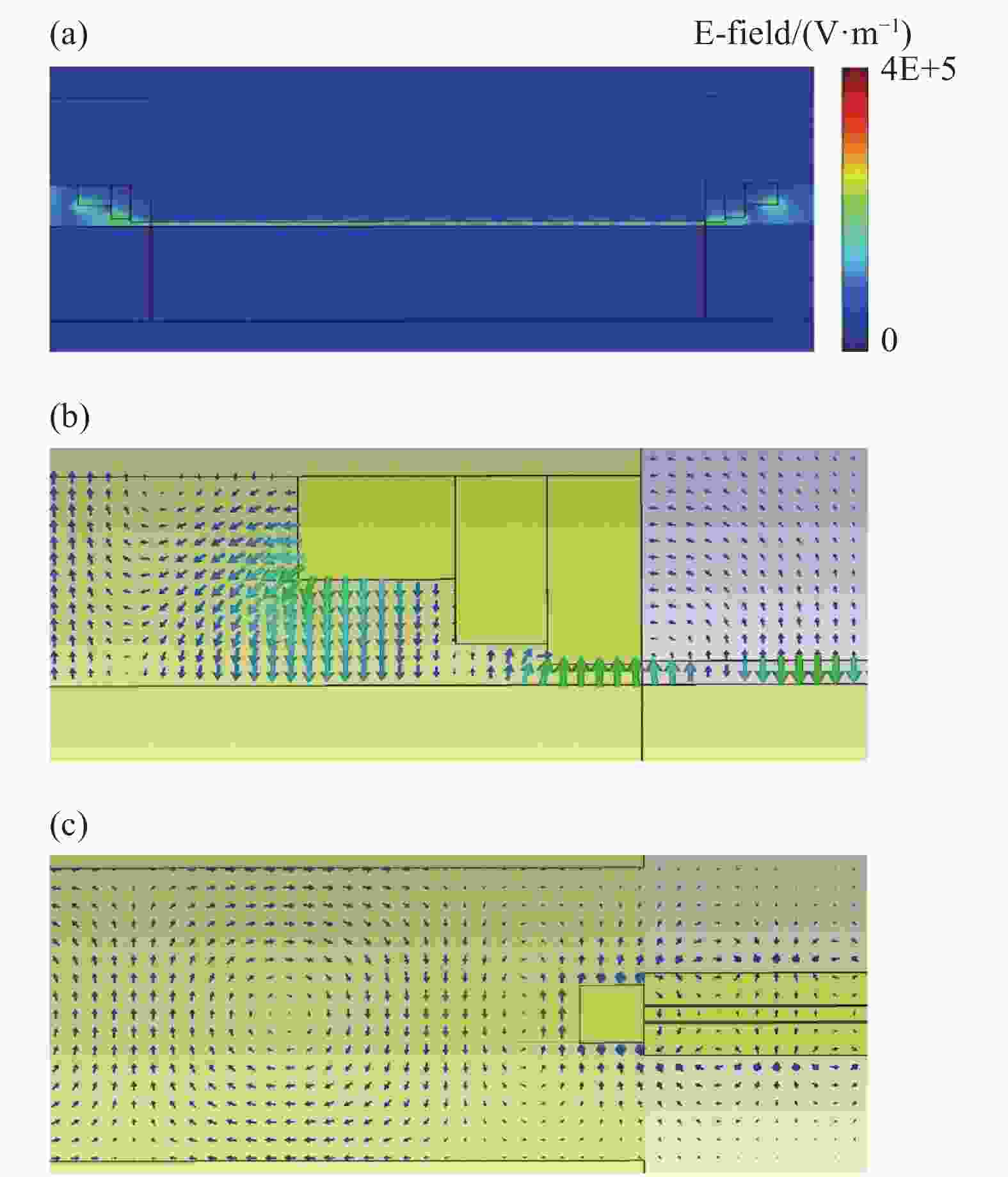
Figure 7. Mode conversion of rectangular waveguide to coplanar waveguide at 305 GHz. (a) Electric field amplitude diagram; (b) Electric field vector diagram; (c) Magnetic field vector diagram
-
该转换结构应用于THz波段故尺寸在微米尺度,为研究加工误差对结构转换效率的影响,文中对阶梯脊圆倒角半径r及转换结构与共面波导间距s对传输系数的影响进行了仿真如图8所示。

Figure 8. Effect of machining error on transmission coefficient of conversion structure. (a) Circular chamfer r; (b) Spacing between the conversion structure and the coplanar waveguide s
图8(a)为阶梯脊圆倒角对转换结构传输系数的影响。结果表明圆倒角半径r由0 μm增加到80 μm在低频段影响很小,在280 GHz以上传输系数会有明显减小。全频段内r小于40 μm可保证转换结构的良好传输特性。图8(b)为间距s对传输系数的影响。结果表明间距小于3 μm不会影响转换效果。
-
文中利用脊波导进行阻抗匹配及电磁场模式转换,结合背敷接地板的常规共面波导,设计了一种在240~350 GHz波段可将矩形波导TE模转换为共面波导TEM模的转换结构。利用CST仿真软件对转换结构阶梯脊高度、长度及厚度等几何参数对耦合器传输性能的影响进行分析,最终确定了转换结构的最优设计。此外还对加工过程中可能存在的阶梯脊圆倒角和装配导致转换结构与共面波导产生间隙的误差进行分析,结果表明圆倒角半径低于40 μm、间隙在3 μm内对结构的影响可以忽略不计。基于此得到了在240~350 GHz全波段传输系数大于−3 dB的转换结构。突破了以往转换结构可用带宽窄、普遍应用于200 GHz以下的限制。该转换结构具有结构简单、加工容错率高的特点,结合共面波导可用于THz分子探测、信息传输等领域。
Design of coupled structure of terahertz rectangular waveguide and coplanar waveguide
doi: 10.3788/IRLA20210733
- Received Date: 2021-11-08
- Rev Recd Date: 2022-01-20
- Publish Date: 2022-08-31
-
Key words:
- terahertz coupled structure /
- ridge waveguide /
- schema transformation
Abstract: Terahertz (THz) wavelength lies in between millimeter waves and infrared waves in the electromagnetic spectrum. The existing optical waveguide and microwave millimeter waves waveguide technologies can be applied to the THz band. Because of the strong absorption of THz waves by water vapour and the limitation of manufacturing processes, THz devices were mainly planar structures and rectangular waveguides were commonly used for THz source and transmission. Therefore, the conversion structure between rectangular waveguides and coplanar waveguides has plays an indispensable role in determining the performance of components and systems. In recent research, the ridge waveguide has been used for impedance matching and electromagnetic field mode conversion to accomplish the high-efficiency coupling between THz wave rectangular waveguides and the coplanar waveguides. According to the simulation of CST microwave studio, the results show that the transmission coefficient (S21


 DownLoad: