


-
惯性导航系统(Inertial Navigation System, INS)是一种利用陀螺仪和加速度计测量载体的角速度和加速度,并实时解算出载体姿态、速度、位置的自主式导航系统[1]。惯性导航系统导航精度的提高可以通过多种途径,其中一种方法是增加惯性器件的数量,构成冗余惯性导航系统(Redundant Inertial Navigation System, RINS)[2-3];也可通过提高惯性器件误差标定精度,将标定结果补偿到惯性器件中,从而有效提高导航精度[4-5]。目前,三轴正交惯导系统的误差标定技术已趋于成熟,针对冗余配置的惯导系统误差标定技术研究相对较少,因此对冗余配置下惯性器件的标定技术进行深入研究十分必要[6]。
目前冗余惯导系统的误差标定主要依托高精度转位机构、转台等测试设备。2014年,赵新强等[7]设计了四位置静态和三位置转动标定方法对斜置冗余捷联惯导系统进行标定,可标定出所有参数。2015年,魏莉莉等[8]针对带斜置冗余元件的光纤陀螺捷联惯导系统进行标定。2016年后,梁海波等[9]、程建华等[10]、李杨等[11]采用Kalman滤波方法实现了冗余惯导系统误差的标定。2020年,Marius V. Gheorghe等[12]提出了一种标定正十二面体冗余传感器配置的新方法。以上研究均需要单轴、双轴或者三轴转台等高精度测试设备辅助实现误差标定,标定效率较低,成本较高,在外场等硬件条件不足的情况下无法进行全误差参数的标定。
因此,王坚等[13]、王岁儿等[14]针对三轴正交惯导系统提出了现场标定方法。随着计算机的发展,杨管金子等[15]、高爽等[16]、戴洪德等[17]将一些智能优化算法应用到现场快速标定问题的求解中,但只能标定出三轴正交惯导系统中加速度计的误差。由于误差模型的不同,以上现场标定方法均不适用于冗余惯导系统。2016年,胡梦纯等[18]提出了一种针对冗余配置光纤惯组系统的不依赖高精度转台的现场标定方法,该方法仅适用于斜置配置的惯导系统。
综上所述,目前并无有效的方法解决正四面体冗余惯导系统的现场快速标定问题。针对这一现状,文中在分析正四面体RINS中的光纤陀螺和加速度计误差的基础上,建立了误差模型,根据解析粗对准姿态误差矩阵与正四面体RINS零偏的关系,利用六位置方案标定出光纤陀螺和加速度计的零偏,之后设计了一种三位置旋转方案标定出光纤陀螺的标度因数和安装误差,利用零偏标定的六位置方案标定出加速度计的标度因数和安装误差,最后通过仿真试验及所在实验室研制的正四面体RINS的实物试验验证了方法的正确性及有效性。
-
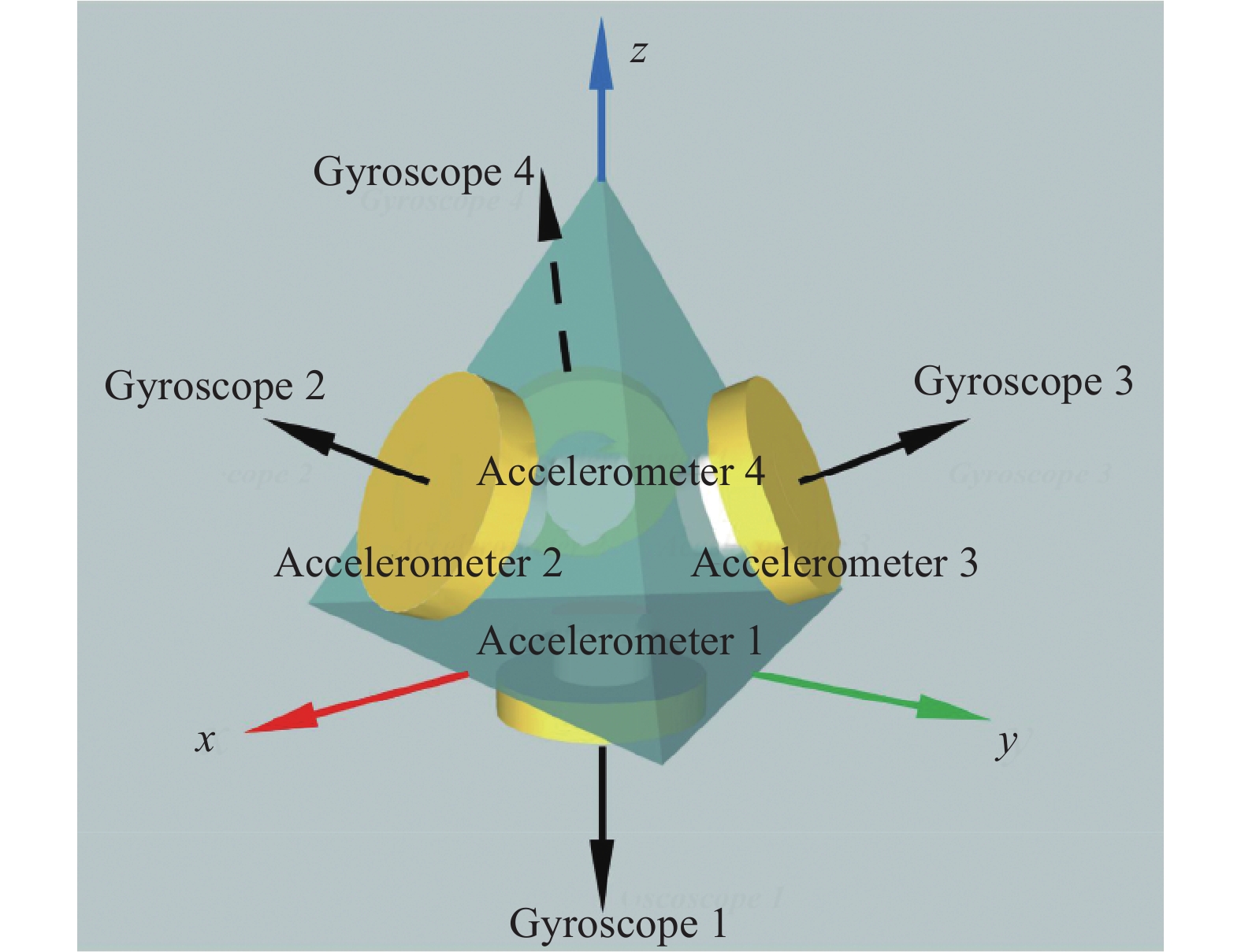
冗余惯导系统包括多种冗余配置方案,如正交冗余配置方案、圆锥冗余配置方案、斜置冗余配置方案等。文中采用的是由四个光纤陀螺和四个石英挠性加速度计组成的正四面体冗余配置方案,如图1所示。

Figure 1. Tetrahedron redundant configuration diagram
以光纤陀螺为例进行分析,正四面体RINS输出角速度
${{\boldsymbol{\omega}} _{m}}$ 为:式中:
${{\boldsymbol{\omega}} _{b}}$ 为载体坐标系中三轴等效角速度;${{\boldsymbol{\omega}} _m}$ 为四个光纤陀螺敏感的角速度;${{\boldsymbol{H}}}$ 为惯导系统的冗余配置矩阵,如公式(2)所示:式中:
$\alpha $ 为正四面体侧面与底面的设计角度,为70.53°;${\;\beta _3}$ 、${\;\beta _4}$ 为陀螺仪3和陀螺仪4敏感轴在xoz平面的投影与ox轴的设计角度,分别为120°、240°。将配置角度数值代入可得具体的四面体配置矩阵如下:
利用最小二乘法可得到等效三轴角速度
$ {\hat{\boldsymbol{ \omega}} _b} $ 的最优估计:惯性器件的误差主要包括确定性误差和随机误差,其中确定性误差包括零偏、标度因数误差和安装误差。
当陀螺仪输入的角速度为0时,输出的值即为零偏。正四面体RINS中的光纤陀螺的零偏
${{{\boldsymbol{B}}}_{g}}$ 为:式中:
$ {b_{g1}} $ 、$ {b_{g2}} $ 、$ {b_{g3}} $ 、$ {b_{g4}} $ 为四个光纤陀螺的零偏。由零偏引起的量测误差
$ \Delta {{\boldsymbol{m}}_b} $ 为:标度因数是输出数字脉冲与输入角速率之比,标度因数不准确引入的误差是标度因数误差。正四面体RINS中的光纤陀螺的标度因数误差
$ \delta {{\boldsymbol{K}}_g} $ 为:式中:
$ {\delta }{{K}_{g1}} $ 、$ {\delta }{{K}_{g2}} $ 、$ {\delta }{{K}_{g3}} $ 、$ {\delta }{{K}_{g4}} $ 为四个光纤陀螺的标度因数误差。由标度因数误差引起的量测误差
$ \Delta {{\boldsymbol{m}}_k} $ 为:由于装配工艺和加工水平有限,光纤陀螺敏感轴的实际指向与设定指向存在偏差,称为安装误差。每个光纤陀螺包含两项安装误差,分别用俯仰角误差
$\delta {u_{gi}}$ 和方位角误差$\delta {v_{gi}}$ 表示。经计算,光纤陀螺包含安装误差的冗余配置矩阵$ {{\boldsymbol{H}}_g} $ 为:式中:
$ {H_{gmn}} $ (m=1, 2, 3, 4; n=x, y, z)为陀螺仪m敏感轴相对n轴由于安装误差导致的交耦系数。式中:
$ \;\beta $ 为陀螺仪1敏感轴与xoz平面的设计角度;$ {\;\beta _1} $ 、$ {\;\beta _2} $ 为陀螺仪1和陀螺仪2敏感轴在xoz平面的投影与ox轴的设计角度。由安装误差引起的量测误差
$ \Delta {{{\boldsymbol{m}}}_h} $ 为:通过上述分析,当考虑光纤陀螺零偏、标定因数误差、安装误差,同时考虑随机误差时,正四面体RINS中光纤陀螺输出角速度
${\omega _m}$ 为:式中:
${\boldsymbol{I}}$ 为单位矩阵;${\boldsymbol\eta _g}$ 为四个光纤陀螺的随机误差。当光纤陀螺输出为数字脉冲时,误差模型表示为:
式中:
$ {{\boldsymbol{N}}_{\omega m}} $ 为光纤陀螺输出数字脉冲;$ {{\boldsymbol{K}}_g} $ 为光纤陀螺的标度因数。同理可得正四面体RINS中加速度计输出加速度
$ {{{\boldsymbol{f}}}_m} $ 为:式中:
$\delta {{\boldsymbol{K}}_f}$ 为加速度计的标度因数误差;$ {{\boldsymbol{H}}_f} $ 为加速度计包含安装误差的冗余配置矩阵;$ {{{\boldsymbol{f}}}_b} $ 为载体坐标系等效三轴加速度;$ {{\boldsymbol{B}}_f} $ 为加速度计的零偏;${{\boldsymbol{\eta}} _f}$ 为加速度计的随机误差。当加速度计输出为数字脉冲时,误差模型表示为:
式中:
$ {{\boldsymbol{N}}_{fm}} $ 为加速度计输出数字脉冲;$ {{\boldsymbol{K}}_f} $ 为加速度计的标度因数。至此,建立了正四面体RINS中光纤陀螺和加速度计的误差模型。
-
文中根据解析粗对准姿态误差矩阵中的非正交、非单位化误差与正四面体RINS中光纤陀螺、加速度计的天向零偏合量的关系标定出正四面体RINS中惯性器件的零偏。解析粗对准是指利用地球重力加速度矢量和地球自转角速度矢量实现惯导系统的对准,不需要其他外部信息。通过惯性器件的测量值可以直接计算出初始捷联矩阵:
式中:
${{\boldsymbol{g}}^n}$ 和$ {\boldsymbol{\omega}} _{ie}^n $ 分别为重力加速度和地球自转角速度在导航系中分量;${{\boldsymbol{g}}^b}$ 和${\boldsymbol{ \omega}} _{ie}^b $ 分别为重力加速度和地球自转角速度在载体系中分量。当解析粗对准存在误差时,姿态误差矩阵为:
式中:
${\delta {\boldsymbol{C}}}_b^n$ 为由陀螺仪和加速度计的零偏等误差引起的姿态误差。根据参考文献[19-20]对解析粗对准误差的分析,解析粗对准的误差主要是对准误差
${{E}_{ss}}$ 和非正交、非单位化误差${{E}_s}$ ,如下所示:式中:
$ {\varphi _U} $ 、$ {\varphi _N} $ 、$ {\varphi _E} $ 分别为天向、北向、东向对准误差;$ {o_U} $ 、$ {o_N} $ 、$ {o_E} $ 分别为天向、北向、东向非正交误差;$ {\eta _U} $ 、$ {\eta _N} $ 、$ {\eta _E} $ 分别为天向、北向、东向非单位化误差。根据参考文献[14]对非正交、非单位化误差与陀螺仪和加速度计零偏的分析可得,天向加速度误差合量、天向陀螺误差合量及北向陀螺误差合量为:
式中:
$ g、\varOmega 、L $ 分别为冗余惯导系统所在位置的重力加速度幅值、地球自转角速度幅值和纬度;$ \delta {f_N} $ 、$ \delta {f_U} $ 为北向、天向加速度误差合量;$ \delta {\omega _N} $ 、$ \delta {\omega _U} $ 为天向陀螺误差合量。由于在实际外场条件下找北比较困难,因此只利用天向陀螺仪误差合量和天向加速度误差合量进行零偏标定。经分析,加速度计的北向零偏合量对天向陀螺仪的零偏合量影响非常小,因此可忽略
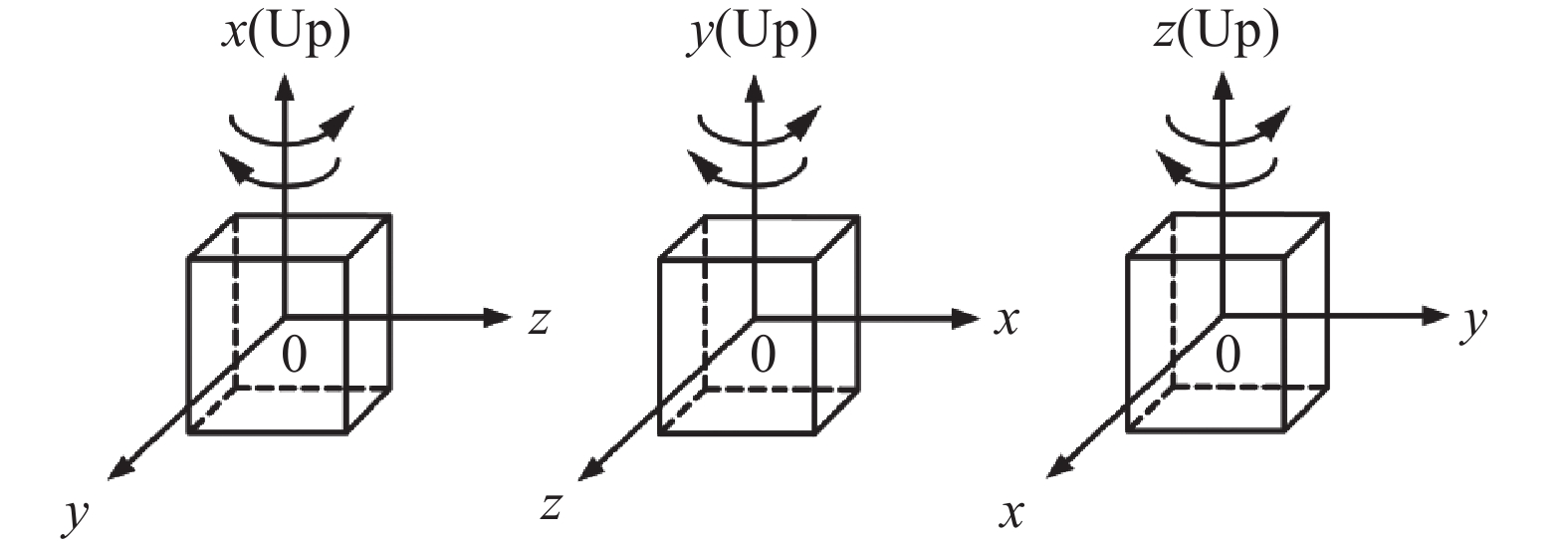
$ \delta {f_N}/g $ 误差项。文中选用一种六位置方案,只需要RINS的三个轴依次指向天和地,如图2所示。每个位置估计的零偏结果如表1所示。
Figure 2. Six-position transposition diagram
Bias Pos1 Pos2 Pos3 Pos4 Pos5 Pos6 $\delta {\hat \omega _U}$ $\delta \hat \omega _{x1}^b$ $ - \delta \hat \omega _{x2}^b$ $\delta \hat \omega _{y1}^b$ $ - \delta \hat \omega _{y2}^b$ $\delta \hat \omega _{z1}^b$ $ - \delta \hat \omega _{z2}^b$ $\delta {\hat f_U}$ $\delta \hat f_{x1}^b$ $ - \delta \hat f_{x2}^b$ $\delta \hat f_{y1}^b$ $ - \delta \hat f_{y2}^b$ $\delta \hat f_{z1}^b$ $ - \delta \hat f_{z2}^b$ Table 1. IMU axial biases for each position estimation
经过计算可得陀螺仪和加速度计三轴等效零偏为:
参考文献[19-20],根据姿态转换矩阵
$ {{\hat {\boldsymbol{C}}}}_b^n $ 计算出非正交、非单位化误差:将公式(24)计算得出的
$ {\hat o_E} $ 、$ {\hat \eta _U} $ 代入公式(21)中,将结果代入公式(22)、(23)中,可求得陀螺仪和加速度计的零偏合量为:将公式(25)、(26)代入公式(1)中,即可计算出四个光纤陀螺和四个加速度计的零偏为:
-
针对现场快速标定问题,使用大理石平台和正六面体工装对正四面体RINS中的惯性器件进行标定。利用三位置手动旋转n圈的方法为正四面体RINS提供角速度输入,利用六位置方法为正四面体RINS提供比力输入,比较陀螺仪和加速度计的输出和输入,可估计出陀螺仪和加速度计的标度因数和安装误差。
-
文中采用三位置手动旋转n圈的方式标定光纤陀螺的标度因数和安装误差,编排方案如图3所示。将正四面体RINS安装于正六面体工装后置于大理石平台上,令x轴朝天,顺时针、逆时针旋转正六面体工装n圈,对y、z轴进行同样的操作,要求在规定时间T内相对均匀地转动n圈。

Figure 3. Three-position rotation scheme
以x轴朝天为例进行分析,当正四面体RINS进行旋转时,光纤陀螺输入的角速度为:
式中:
$ {\omega _{ix}}\left( t \right) $ 为手动旋转时瞬时角速度;$ \theta \left( t \right) $ 为手动旋转累积转动角度。将公式(28)代入公式(13),两边求积分再相减可得:
式中:n为旋转圈数;T为规定的时间;
$ N_{\omega 1}^{x + } $ 、$ N_{\omega 1}^{x - } $ 分别为正四面体RINS绕x轴顺时针、逆时针旋转时陀螺仪1的输出。令
$ {K_{gmn}}{\text{ = }}{K_{gm}}{H_{gmn}} $ (m=1, 2, 3, 4; n=x, y, z),同理可求得$ {K_{g2 x}} $ 、$ {K_{g3 x}} $ 、$ {K_{g4 x}} $ ,当y轴朝天时可求得$ {K_{g1 y}} $ 、$ {K_{g2 y}} $ 、$ {K_{g3 y}} $ 、$ {K_{g4 y}} $ ,当z轴朝天时可求得$ {K_{g1 z}} $ 、$ {K_{g2 z}} $ 、$ {K_{g3 z}} $ 、$ {K_{g4 z}} $ 。归一化可求得正四面体RINS中的光纤陀螺的标度因数和安装误差导致的交耦系数:
-
使用零偏标定所设计的六位置编排次序进行标定,如图2所示。将位置1和位置2的加速度计输入代入误差模型公式(15)中,可得:
将公式(32)与公式(33)相减可得:
式中:
$ {K_{fm}} $ (m=1, 2, 3, 4)为第m个加速度计的标度因数;$ {H_{fmx}} $ 为第m个加速度计敏感轴相对x轴由于安装误差导致的交耦系数;$ N_{fm}^1 $ 、$ N_{fm}^2 $ 分别为位置1和位置2第m个加速度计的输出。令
$ {K_{fmn}}{\text{ = }}{K_{fm}}{H_{fmn}} $ (m=1, 2, 3, 4; n=x, y, z),由剩下四个位置可求得$ {K_{fmy}} $ 和$ {K_{fmz}} $ 。归一化可求得加速度计的标度因数和安装误差导致的交耦系数: -
为验证文中提出的正四面体RINS现场快速标定方法的有效性,进行了仿真试验。设当地地理纬度为40.356°,经度为116.67°,正四面体RINS所在高度为50 m。惯性器件采样周期为200 Hz,光纤陀螺和加速度计的误差参数设定如表2~3所示。
Parameter Gyro
scope 1Gyro
scope 2Gyro
scope 3Gyro
scope 4Bias/(°)·h−1 0.6 0.5 −0.3 0.4 Scale factor/bits·((°)/s)−1 170000 170000 170000 170000 Installation error $\delta {u_{gi}}$
/(″)40 40 40 40 Installation error $\delta {v_{gi}}$
/(″)40 40 40 40 Noise/(°)·h−1/2 0.01 0.01 0.01 0.01 Table 2. Setting values of gyroscope error parameters
Parameter Accelerometer 1 Accelerometer 2 Accelerometer 3 Accelerometer 4 Bias/mg 0.3 0.2 −0.4 0.5 Scale factor
/bits·((°)/s)−11 1 1 1 Installation error $\delta {u_{fi}}$
/(″)40 40 40 40 Installation error $\delta {v_{fi}}$
/(″)40 40 40 40 Noise/mg·h−1/2 0.02 0.02 0.02 0.02 Table 3. Setting values of accelerometer error parameters
按照图2所示的六位置编排方案生成静态冗余惯导系统的仿真数据,每个位置采集2 min数据,计算光纤陀螺的零偏和加速度计的零偏、标度因数及安装误差估计结果。按照图3所示的三位置旋转方案生成冗余惯导系统中光纤陀螺的仿真数据,计算光纤陀螺的标度因数和安装误差。仿真结果如表4所示,可见提出的现场快速标定方法可有效估计得到标定结果,其中惯性器件的零偏标定结果误差在7%以内,标度因数的标定结果误差在0.1%以内,安装误差导致的交耦系数的标定结果误差在0.1%以内,对加速度计的误差标定精度高于光纤陀螺的误差标定精度。
Fiber optic gyroscope parameters Preset Simulation results Error Accelerometer parameters Preset Simulation results Error ${b_{g1} }/{(^\circ)\cdot {\rm{h} }^{-1} }$ 0.6 0.5874 2.10% ${b_{f1} }/{\rm{mg}}$ 0.3 0.3056 1.87% ${b_{g2} }/{(^\circ)\cdot {\rm{h} }^{-1} }$ 0.5 0.5098 1.96% ${b_{f2} }/{\rm{mg}}$ 0.2 0.1991 0.45% ${b_{g3} }/{(^\circ)\cdot {\rm{h} }^{-1} }$ −0.3 −0.2877 4.10% ${b_{f3} }/{\rm{mg}}$ −0.4 −0.3926 1.85% ${b_{g4} }/{(^\circ)\cdot {\rm{h} }^{-1} }$ 0.4 0.3753 6.18% ${b_{f4} }/{\rm{mg}}$ 0.5 0.4991 0.18% ${ {K}_{g1} }/{\rm{bits} }\cdot({(^\circ)/ {\rm{s} })^{-1} }$ 170000 170142.54048690 0.0838% ${ {K}_{f1} }/{\rm{bits} }\cdot{({\rm{m/s^2} }) ^{-1} }$ 1 1.00000447 0.000004% ${ {K}_{g2} }/{\rm{bits} }\cdot({(^\circ)/ {\rm{s} })^{-1} }$ 170000 170024.96320257 0.0147% ${ {K}_{f2} }/{\rm{bits} }\cdot{({\rm{m/s^2} }) ^{-1} }$ 1 0.99965628 0.0003% ${ {K}_{g3} }/{\rm{bits} }\cdot({(^\circ)/ {\rm{s} })^{-1} }$ 170000 169981.63378409 0.0108% ${ {K}_{f3} }/{\rm{bits} }\cdot{({\rm{m/s^2} }) ^{-1} }$ 1 1.00019696 0.0002% ${ {K}_{g4} }/{\rm{bits} }\cdot({(^\circ)/ {\rm{s} })^{-1} }$ 170000 169981.53174746 0.0109% ${ {K}_{f4} }/{\rm{bits} }\cdot{({\rm{m/s^2} }) ^{-1} }$ 1 0.99979333 0.0002% $ {H_{g1 x}} $ $1.939\;255 \times {10^{ - 4}}$ ${{1}}{{.939\;254}} \times {10^{ - 4}}$ 0.0001% $ {H_{f1 x}} $ $1.939\;255 \times {10^{ - 4}}$ ${{1}}{{.939\;257}} \times {10^{ - 4}}$ 0.0001% $ {H_{g1 y}} $ $1.939\;255 \times {10^{ - 4}}$ $1.939\;254 \times {10^{ - 4}}$ 0.0001% $ {H_{f1 y}} $ $1.939\;255 \times {10^{ - 4}}$ $1.939\;258 \times {10^{ - 4}}$ 0.0002% $ {H_{g1 z}} $ −1 −0.999999 0.0001% $ {H_{f1 z}} $ $ - 1$ −0.999999 0.0001% $ {H_{g2 x}} $ 0.942633 0.942775 0.0151% $ {H_{f2 x}} $ 0.942633 0.942775 0.0151% $ {H_{g2 y}} $ $ {{ - }}2.474\;740 \times {10^{ - 4}} $ ${{ - 2}}{{.472\;355}} \times {10^{ - 4}}$ 0.0964% $ {H_{f2 y}} $ $ - 2.474\;740 \times {10^{ - 4}} $ ${{ - 2}}{{.472\;524}} \times {10^{ - 4}}$ 0.0896% $ {H_{g2 z}} $ 0.333378 0.333428 0.0150% $ {H_{f2 z}} $ 0.333378 0.333429 0.0153% $ {H_{g3 x}} $ −0.471261 −0.471270 0.0019% $ {H_{f3 x}} $ −0.471261 −0.471236 0.0053% $ {H_{g3 y}} $ 0.816626 0.816554 0.0088% $ {H_{f3 y}} $ 0.816626 0.816583 0.0053% $ {H_{g3 z}} $ 0.333378 0.333384 0.0018% $ {H_{f3 z}} $ 0.333378 0.333361 0.0051% $ {H_{g4 x}} $ −0.471373 −0.471427 0.0115% $ {H_{f4 x}} $ −0.471373 −0.471418 0.0095% $ {H_{g4 y}} $ −0.816379 −0.816450 0.0087% $ {H_{f4 y}} $ −0.816379 −0.816458 0.0097% $ {H_{g4 z}} $ 0.333378 0.333416 0.0114% $ {H_{f4 z}} $ 0.333378 0.333409 0.0093% Table 4. Simulation results
-
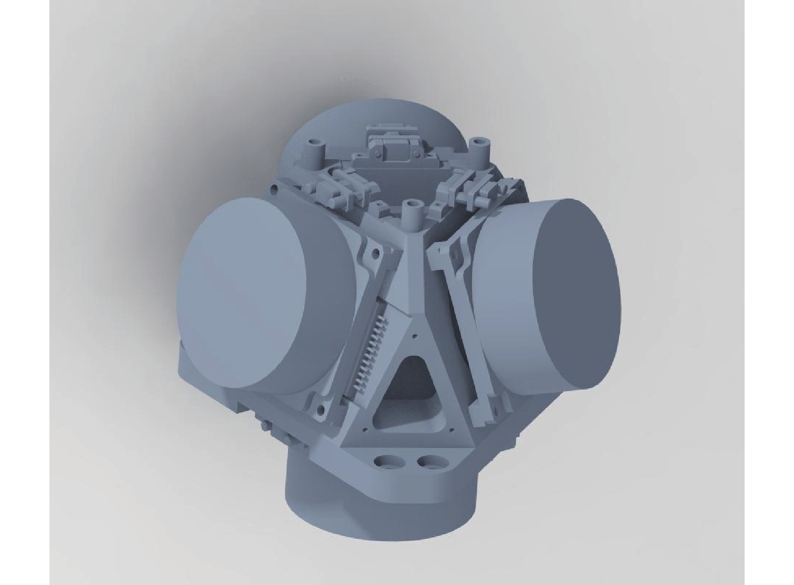
为进一步验证正四面体RINS现场快速标定方法,使用所在实验室研制的正四面体RINS进行标定试验。该系统由四个光纤陀螺和四个石英挠性加速度计组成,系统结构如图4所示,器件技术规格如表5所示。将正四面体RINS装入正六面体工装后放置于大理石平台上搭建试验环境,如图5所示。

Figure 4. Structure diagram of tetrahedral redundant inertial navigation system
Parameter name Parameter indicator Fiber optic gyroscope bias stability$/{(^\circ)\cdot {\rm{h} }^{-1} }$ $ \leqslant $0.1 Fiber optic gyroscope scale factor$/{\rm{bits} }\cdot({(^\circ)/ {\rm{s} })^{-1} }$ 176000±5000 Accelerometer bias stability$/\text{μ} {\rm{g}}$ 50 Accelerometer scale factor$/{\rm{mA} } \cdot{{ g} }^{-1}$ 1.1-1.5 Table 5. Technical specification of fiber optic gyroscope and accelerometer

Figure 5. Experiment equipment and environment
-
在试验开始前对系统预热1 h,进行六位置试验,将系统x、y、z轴分别朝天和地,每个位置采集2 min静态数据,共12 min;然后进行三位置旋转试验,将系统x、y、z轴朝天,以大理石平台的侧面作为基准,分别顺时针、逆时针旋转正六面体工装三圈,旋转前后要求同一个面与大理石平台的侧面重合,同时要求1.5 min内完成三圈旋转,共9 min。上述两步标定共需21 min。按照上述原理计算标定结果,光纤陀螺误差标定结果如表6所示,加速度计误差标定结果如表7所示。
Fiber optic gyroscope parameters Calibration results Fiber optic gyroscope parameters Calibration results ${b_{g1} }/{(^\circ)\cdot {\rm{h} }^{-1} }$ 0.0541 ${ {K}_{g1} }/{\rm{bits} }\cdot({(^\circ)/ {\rm{s} })^{-1} }$ 172207.11 ${b_{g2} }/{(^\circ)\cdot {\rm{h} }^{-1} }$ 0.0524 ${ {K}_{g2} }/{\rm{bits} }\cdot({(^\circ)/ {\rm{s} })^{-1} }$ 177573.77 ${b_{g3} }/{(^\circ)\cdot {\rm{h} }^{-1} }$ 0.0780 ${ {K}_{g3} }/{\rm{bits} }\cdot({(^\circ)/ {\rm{s} })^{-1} }$ 179823.99 ${b_{g4} }/{(^\circ)\cdot {\rm{h} }^{-1} }$ −1.1961 ${ {K}_{g4} }/{\rm{bits} }\cdot({(^\circ)/ {\rm{s} })^{-1} }$ 171997.12 $ {H_{g1 x}} $ −0.0015 $ {H_{g3 x}} $ −0.4703 $ {H_{g1 y}} $ −0.0034 $ {H_{g3 y}} $ 0.8168 $ {H_{g1 z}} $ −1.0000 $ {H_{g3 z}} $ 0.3340 $ {H_{g2 x}} $ 0.9418 $ {H_{g4 x}} $ −0.4673 $ {H_{g2 y}} $ 0.0016 $ {H_{g4 y}} $ −0.8186 $ {H_{g2 z}} $ 0.3362 $ {H_{g4 z}} $ 0.3339 Table 6. Gyroscope error calibration results
Accelerometer parameters Calibration results Accelerometer parameters Calibration results ${b_{f1} }/{{g} }$ −0.0167 ${ {K}_{f1} }/{\rm{bits} }\cdot{({\rm{m/s^2} }) ^{-1} }$ 0.9680 ${b_{f2} }/{{g} }$ 0.0087 ${ {K}_{f2} }/{\rm{bits} }\cdot{({\rm{m/s^2} }) ^{-1} }$ 0.9687 ${b_{f3} }/{{g} }$ 0.0109 ${ {K}_{f3} }/{\rm{bits} }\cdot{({\rm{m/s^2} }) ^{-1} }$ 0.9907 ${b_{f4} }/{{g} }$ −0.0029 ${ {K}_{f4} }/{\rm{bits} }\cdot{({\rm{m/s^2} }) ^{-1} }$ 0.9516 $ {H_{f1 x}} $ ${ { - } }3.159\;0 \times {10^{ - 5} }$ $ {H_{f3 x}} $ −0.4734 $ {H_{f1 y}} $ ${ { - } }1.225\;7 \times {10^{ - 4} }$ $ {H_{f3 y}} $ −0.8152 $ {H_{f1 z}} $ −1.0000 $ {H_{f3 z}} $ 0.3337 $ {H_{f2 x}} $ 0.9428 $ {H_{f4 x}} $ −0.4696 $ {H_{f2 y}} $ −0.0019 $ {H_{f4 y}} $ −0.8173 $ {H_{f2 z}} $ 0.3335 $ {H_{f4 z}} $ 0.3338 Table 7. Accelerometer error calibration results
-
为验证标定结果的有效性,将正四面体RINS放置于大理石平台上连续采集约1 h数据进行静基座导航试验,分别解算原始数据和误差补偿后正四面体RINS的姿态、速度和位置变化,结果如图6~8所示。从图6可以看出,标定后的正四面体RINS的横滚角、俯仰角和航向角精度和稳定性更高。从图7可以看出,利用原始数据解算的东向速度和北向速度出现很大偏移,标定后速度稳定性和精度有很大的提升。如图8所示,标定后1 h北向位置误差从61.0655 km降低至0.4767 km,1 h东向位置误差从161.2027 km降低至4.8422 km。试验结果表明,经过现场快速标定方法标定后,有效提升了RINS的导航精度,验证了该方法的有效性。

Figure 6. Attitude error of navigation solution

Figure 8. Position error of navigation solution

Figure 7. Velocity error of navigation solution
-
为进一步验证标定结果的有效性,根据三轴转台试验进行结果验证,转台的角分辨率优于1.5"。将x、y、z轴朝天放置,然后将转台绕外框轴方向以10 (°)/s的速度进行旋转,记录四个光纤陀螺的输出数据。然后分别将x、y、z轴朝天和朝地放置,记录四个加速度计的输出数据。将现场快速标定方法计算出的误差结果代入到误差模型中,根据输出数据利用最小二乘法得到等效三轴角速度和加速度,以转台设定值作为标准值进行对比,结果如表8和表9所示。
Rotating way Standard value/(°)·s−1 Factory parameter Calibration parameter Compensation result
/(°)·s−1Relative error Compensation result
/(°)·s−1Relative error x(clockwise) 10 10.0126 0.00126 9.9932 −0.00068 x(counterclockwise) −10 −9.9687 −0.00313 −10.0011 0.00011 y(clockwise) 10 9.9842 −0.00158 9.9967 −0.00037 y(counterclockwise) −10 −9.9825 −0.00175 −9.9903 −0.00097 z(clockwise) 10 9.9709 −0.00291 9.9995 −0.00005 z(counterclockwise) −10 −9.9599 −0.00401 −10.0046 0.00046 Table 8. Gyroscope turntable test results
Position Standard value/m·s2 Factory parameter Calibration parameter Compensation result/m·s2 Relative error Compensation result Relative error x(up) 9.8014 9.8046 3.2648 E-4 9.8022 −8.1621 E-5 x(down) −9.8014 −9.7952 −6.3256 E-4 −9.8014 0 y(up) 9.8014 9.8020 6.1216 E-5 9.8011 3.06079 E-5 y(down) −9.8014 −9.7987 −2.7547 E-4 −9.8017 −3.0608 E-5 z(up) 9.8014 9.7957 −5.8155 E-4 9.8029 −1.5304 E-4 z(down) −9.8014 −9.7994 −2.0405 E-4 −9.8029 −1.5304 E-4 Table 9. Accelerometer turntable test results
从表8和表9中的结果可看出,该现场快速标定方法标定出的误差参数补偿到惯性器件中,其结果相对误差均小于出厂参数补偿后的结果,再次证明该方法的有效性。
-
(1) 提出一种针对正四面体RINS误差标定方法,可标定出光纤陀螺和加速度计的所有确定性误差参数,包括零偏、标度因数和安装误差,无需使用高精度转位结构、转台等测试设备,简便灵活,实用性强,耗时较短,适用于多种场合。
(2) 通过仿真试验可以看出,该方法可有效标定出惯性器件的所有误差参数。从静基座导航试验结果可以看出,标定后的导航效果明显优于未进行标定的导航效果,验证了该方法的正确性。转台试验结果再次验证了标定方法的有效性,为其他冗余配置惯导系统的现场快速标定研究提供了重要参考。
Full parameter rapid field calibration method for regular tetrahedral redundant inertial navigation
doi: 10.3788/IRLA20210784
- Received Date: 2021-10-26
- Rev Recd Date: 2022-02-21
- Available Online: 2022-08-13
- Publish Date: 2022-08-05
Fund Project:
National Natural Science Foundation of China (11772001);Youth Top-Notch Talent Support Program of Beijing, China (2017000026833 ZK23)
-
Key words:
- Redundant Inertial Navigation System (RINS) /
- rapid field calibration /
- three-position rotation /
- error modeling /
- regular tetrahedron
Abstract: Regular tetrahedral Redundant Inertial Navigation System (RINS) has the characteristics of high reliability and high precision, and error calibration is a necessary means to realize high-precision navigation solution. At present, the error calibration of regular tetrahedral RINS needs to be realized by using the high-precision turntable, which not only has high calibration cost and long calibration time, but also cannot calibrate full error parameters under the condition of insufficient hardware conditions such as external field. Address this issue, a rapid field calibration method for full error parameters of regular tetrahedral RINS without high-precision turntable was proposed. Firstly, the error model of regular tetrahedral RINS was established. Then, according to the relationship between the analytic coarse alignment attitude error matrix and the bias of regular tetrahedral RINS, a bias calibration method based on six positions was proposed. Then, a three-position rotation scheme was designed to calibrate the scale factor and installation error of the gyroscope. Finally, the six-position scheme of bias calibration was used to calibrate the scale factor and installation error of the accelerometer. Simulation and experiment show that this method can effectively calibrate full error parameters. In the 1h static base navigation experiment, the north positioning accuracy are improved from 61.065 5 km to 0.476 7 km, and the east positioning accuracy are improved from 161.202 7 km to 4.842 2 km.


 DownLoad: