


-
苍蝇、昆虫等动物的复眼以其广阔的视场,对高速运动的物体有出色的灵敏度以及紧凑的光学结构而著名。仿生复眼系统模拟生物复眼可以提供紧凑的光学结构,同时具有许多优点,如视场大、空间分辨率高、对高速运动的物体较灵敏、能够检测偏振信息等[1-2],在医疗、军事、工业等领域中广泛应用[3],因此受到学者们广泛关注,进行了大量的研究。例如:张远杰等[4]等设计的曲面仿生复眼测速系统,由曲面仿生复眼辅以光学中继系统,系统视场达到98°;张家铭[5]等设计了的曲面仿生复眼系统;许黄蓉[6-7]等设计了120°的大视场成像的复眼系统;史成勇[8-9]等设计的圆形复眼阵列,通过中继系统拉平像场,系统视场达到122.4°;于晓丹[10-11]等设计的曲面复眼透镜阵列配合滤光片及光中继转向系统,该系统视场达到138°。上述传统曲面仿生复眼配合中继系统的一次像面为弯曲像场,中继系统承担大视场的弯曲物面转化成平像场的任务,设计难度较大。此外,还有光学结构是不通过光学中继系统,直接采用不同焦距的复眼成像在平面探测器上。例如:程阳[12]等通过在曲面基底上排布多焦距的子眼,实现105°视场角的复眼系统;邸思[13]等提出了一种非均一曲面复眼透镜结构,在曲面基底不同环形阵列上排布不同焦距子眼透镜,最终成像在平面CMOS上。这种结构的优势是结构简单,但是存在分辨率低、边缘视场容易出现离焦等问题。
文中为了解决传统曲面复眼中继系统承担大视场平像场任务、设计难度大的问题,提出了一种大视场复眼平像面拼接光学结构。通过构建子眼个数、系统总视场角以及合理选取光中继系统相关参数之间的平衡模型,利用子眼的空间排布,使得在实现大视场的同时复眼子眼的像面中心在同一平面上,拼接后的系统像面对于光学中继系统来说,虽然为非连续且有一定光程差的平面波前,但是和通常情况下采用高分辨率探测器的中继系统景深相比可以忽略不计,能有效降低传统曲面复眼系统中继系统需要承担平像场的设计难度,证明了该拼接方法理论可行,并基于该方法设计了一种复眼成像光学系统,进行了实践验证,最终实现了小光学代价下的大视场复眼光学系统的高质量成像。
-
上述传统曲面仿生复眼系统、多焦距复眼系统和平像面拼接复眼系统的结构对比如图1所示。对比图1(a)、(c)可以看出相比传统曲面复眼,平像面拼接方法在中继之前将曲面像变换为相对平面像。

Figure 1. Comparison of bionic compound eye. (a) Traditional curved compound eye; (b) Multifocal curved compound eye; (c) Flat-plane splicing compound eye
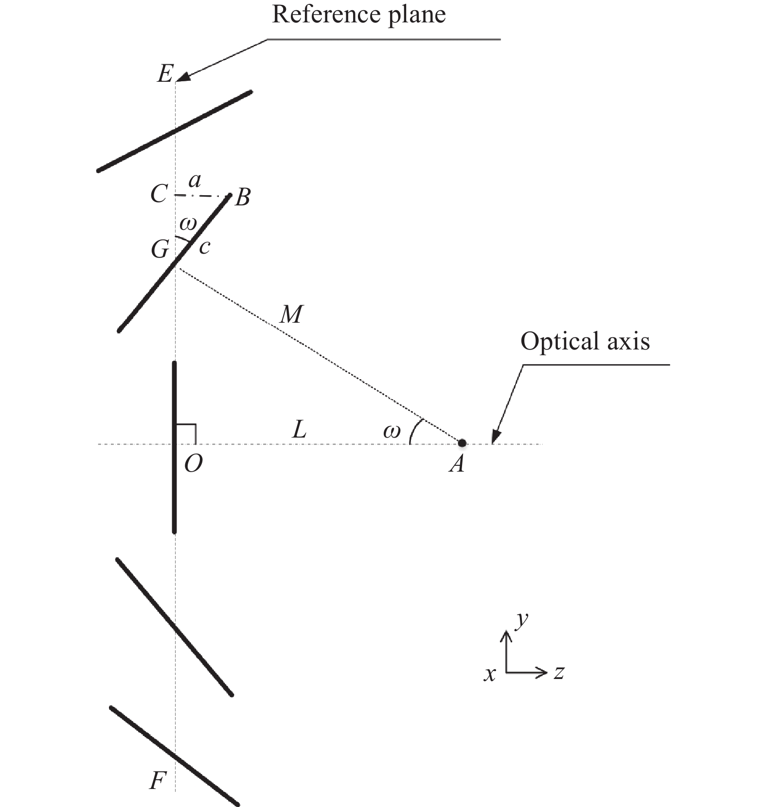
大视场平像面拼接采用复眼系统中各子眼一次像面中心点排列在同一平面上的方法,将一次弯曲像面转换为相对平面,以降低传统曲面复眼中继系统承担平像场的设计难度。但此种方式会造成波面不连续且相对平面波引入光差,平像面拼接模型如图2所示。
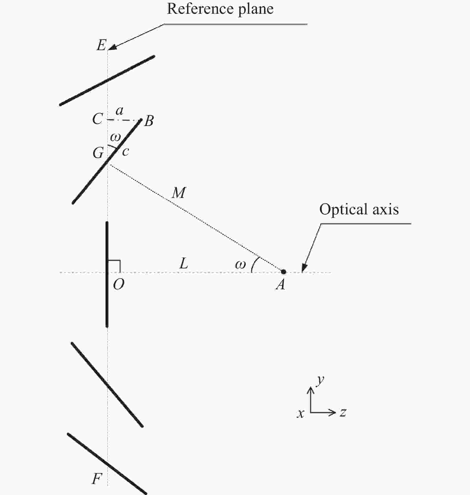
Figure 2. Flat-plane splicing
在图2中, A点为系统主光轴上复眼视场拼接围绕其旋转的点。设中央子眼像面所在平面EF为参考面,O点为参考面EF与系统主光轴的交点,B点为某级子眼一次像面边缘位置,从B点向相对平面参考面EF作垂线,交参考面EF于C点,即BC垂直于EF平面,G点为该级子眼的一次像面与参考面EF的交点。设BC=a、BG=c,OA的距离为L,GA的距离为M,该级子眼光轴与中继系统光轴的夹角为
$ \omega $ ,在△OGA中有:利用公式(1)使复眼各子眼一次像面中心点排列在同一平面上。复眼系统的总视场角可以表示为:
式中:
$ \theta $ 为总视场;$ n $ 为Y方向排布复眼个数;$ \beta $ 为相邻子眼光轴夹角,同时有$ \omega = n\beta $ ;$ 2\alpha $ 为单子眼视场角。在无视场重叠[14]和间隙的情况下,$ \omega $ =$ 2 n\alpha $ 。将公式(2)进一步推导有:如图2中可以明显看出,平像面拼接排列后的像面不是一个理想的平像面,会产生波面的不连续,轴外视场的各级子眼像面与理想波面之间引入一定的光程差。在△BCG中,a、c、
$ \omega $ 之间满足正弦关系:式中:c同时为单子眼线视场;a同时为该级子眼像面相对理想平面波造成的光程差,即平像面拼接引入的光程差
${D_{{\rm{OP}}}}$ ,可以表示为:根据公式(5),对一定系统总视场
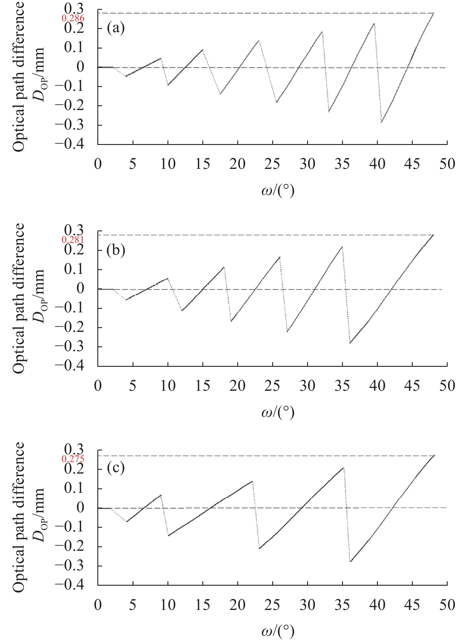
$ \theta $ 下,不同子眼个数$ n $ 和平像面光程差${D_{{\rm{OP}}}}$ 之间的关系进行仿真。设定系统总视场角为96°,分别对子眼数13、11、9的像面光程差进行计算,结果如图3所示。其中横坐标$ \omega $ 表示各子眼与中继系统光轴的夹角,纵坐标表示相对理想平面波的光程差。子眼个数13、11、9分别对应光轴夹角为6.6°、8°、10°。
Figure 3. Optical path difference under different number of eyes. (a) 13; (b) 11; (c) 9
图3(a)~(c)分别表示在系统总视场96°的情况下,子眼数量为13、11、9时光程差与各子眼和中继系统光轴的夹角之间的关系。因为复眼系统的各级子眼是关于中继系统光轴上下对称排布的,所以光程差的大小关于光中继系统光轴呈对称分布。从图3可以看出,平像面拼接排列后的像面光程差曲线表现为不连续折线状,随着
$ \omega $ 的增大而增大,最边缘子眼的光程差为最大。随着子眼个数的减少,为了保证总视场的无缝拼接,单个子眼视场增大,子眼间光轴夹角增大,最大的光程差却在减少。子眼个数为13时最大光程差为0.286,11时最大光程差为0.281,9时最大光程差为0.275。也就是说,在这种拼接模式下,更少的子眼数量可以获得更小的光程差,但是单个子眼也会因为视场过大产生设计压力,需要进行平衡设计。转换像面所产生的光程差对后续中继系统造成影响,可以用景深进行评判。以衍射极限下的图像探测器像元尺寸p作为分辨极限的焦深范围对应在物面处的景深M,表达为[15]:
式中:F为中继系统焦距与通光口径的比值;f为中继焦距;u为中继物距;D为中继系统口径大小。
当最大的光程差满足
${D_{{\rm{OP}}}}$ $ \le $ 景深M时,此时满足成清晰像的条件,可以忽略误差认为平像面拼接得到的是理想平面,可以有效地降低光中继设计难度,证明该拼接方法理论可行。由公式(5)、(6)可以得到公式(7):通过公式(7),可以在该条件下合理构建子眼个数
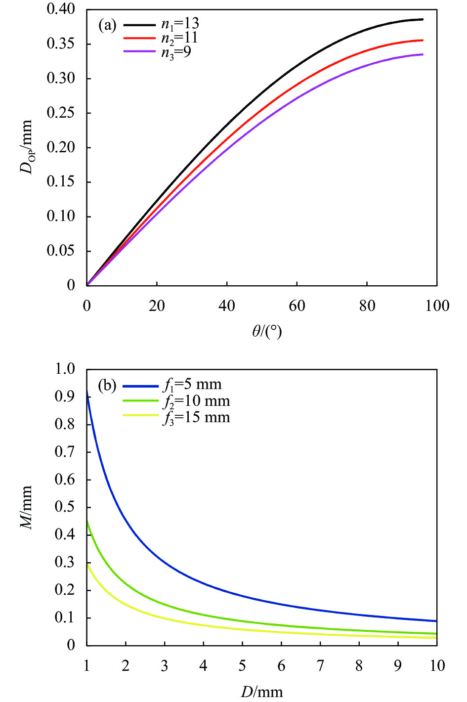
$ n $ 、总视场$ \theta $ 、中继系统参数三者之间的平衡模型。对公式(7)进行仿真,结果如图4、图5所示。图4(a)给出c=0.4 mm、子眼个数$ n $ 分别为13、11、9时不同总视场$ \theta $ 下对应的最大光程差,可以看出当子眼个数一定时,光程差随着$ \theta $ 的增大而增大。图4(b)给出当探测器像元大小p=5 μm,物距u=30 mm,焦距f为5 mm、10 mm和15 mm时不同口径D对应下的景深,可以看出在一定中继系统参数范围内景深的变化。对比图4(a)、(b)的曲线对应的纵坐标值,将选定子眼个数在不同总视场$ \theta $ 下的光程差与选定中继系统参数f、D下的景深值进行对比,当光程差小于中继景深时满足成清晰像的条件。
Figure 4. Maximum optical path difference, depth of field curve at different parameters. (a) Maximum optical path difference for different n,
$ \theta $ ; (b) Depth of field at different f, D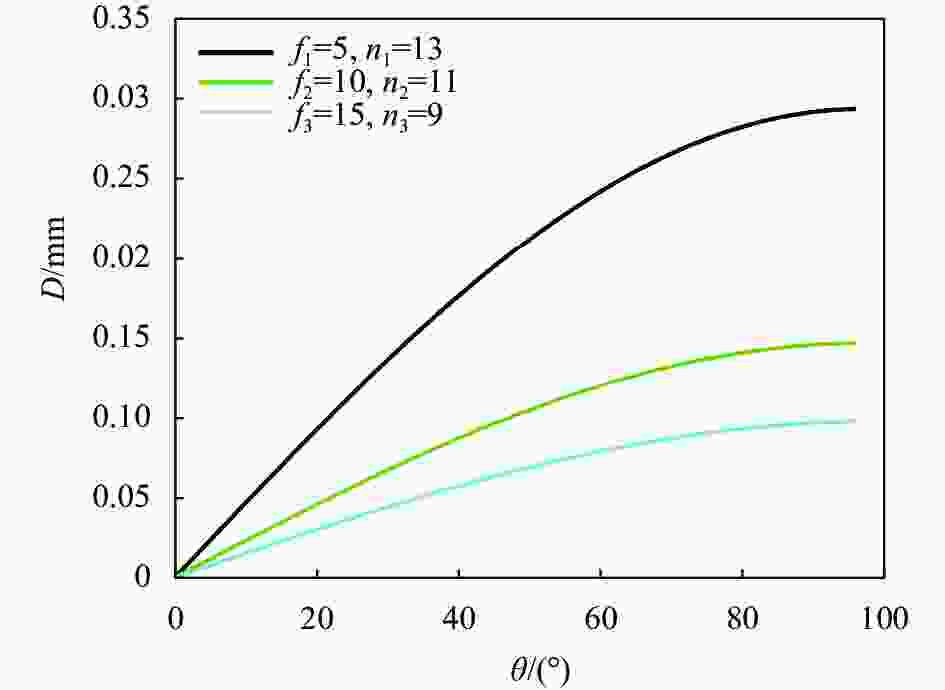
Figure 5. The corresponding relay D under different f, n,
$ \theta $ 公式(7)中当最大光程差
${D_{{\rm{OP}}}}$ =景深M时,可以得到如下仿真结果。图5中横坐标表示总视场,纵坐标表示中继系统口径D,当f和n选定时,D随着总视场的增大而增大。通过公式(7)合理排布子眼的位置及个数后,可以进一步指导中继系统的参数设计,帮助系统总体设计在经济成本和光学指标中做出平衡选取。取常用探测器像元大小p=5 μm为例,通过公式(6)计算出参数为焦距f=5 mm、D=3 mm、u=30 mm的典型中继系统景深为546λ,当光程差小于该中继系统景深便可以忽略误差,认为平物面拼接后得到的是理想平面,可以有效地降低光中继设计难度。基于该方法设计一种大视场复眼光学系统,进行实践验证。
-
通过平像面拼接排列的方法使各子眼一次像面中心点排列在同一平面上。整体复眼系统由两部分构成:曲面复眼透镜阵列和中继系统。系统的总视场角为96°,长度为84 mm,系统工作波长为0.4~0.9 μm。单子眼的视场为16°,由两片透镜组成。优化后的光学中继系统由九片透镜组成,焦距为5 mm,视场角为120°。在进行系统组合设计时要注意光瞳匹配原则,曲面复眼透镜阵列的出瞳位置应是光学中继系统的入瞳位置。组合后系统的像差主要由中继系统决定,系统的光阑位置位于中继系统的中间位置处。最终系统设计参数如表1所示。
Design objective Standard requirement Acceptance angle of each
ommatidium 2α/(°)16 Number of ommatidia n 11 Focal length of relay system/mm 5 Diameters of relay system D/mm 3 Total FOV of the system $ \theta $/(°) 96 Wavelength range λ/μm 0.4-0.9 Focal length f/mm 0.5 Table 1. Optical parameters of compound eye system with large field of view
系统组合后的总体视场角为96°,目标在中心和边缘部分都能清晰成像,并且相关像差得到校正。曲面复眼系统整体布局如图6所示。
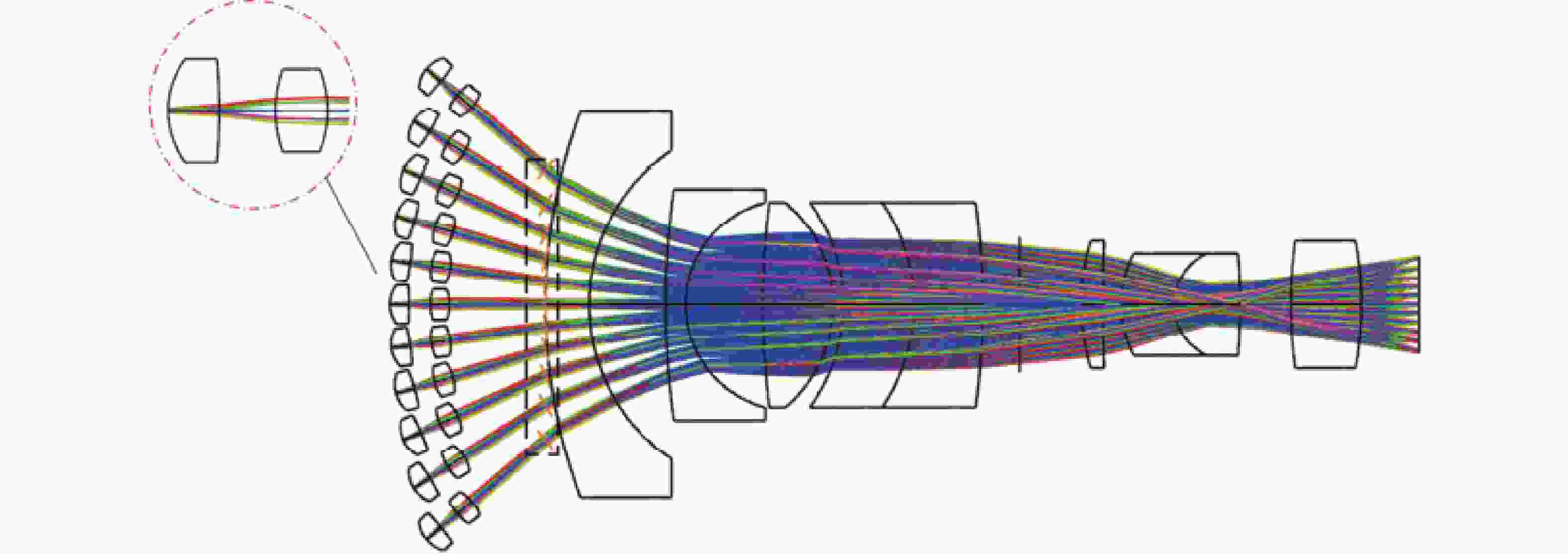
Figure 6. Optical layout of the bionic compound eye imaging system
由于弯曲复眼中所有子眼全部对称排列,仅选取中心子眼和最边缘子眼进行分析。图7(a)为中心子眼的场曲和畸变图,可以看出场曲小于0.1 mm,畸变小于1%,满足大部分应用的成像要求。图7(b)为中心子眼的点列图,可以看出RMS值均在艾里斑半径内,说明像质满足一定要求。图7(c)为中心子眼的MTF曲线图,可以看出在80 lp/mm的奈奎斯特频率下,MTF值接近0.6,表明可以获得较好的成像质量。图7(d)为中心子眼波前图,可以看出波峰到波谷为0.086λ,成像质量满足要求。

Figure 7. Simulation results for central ommatidium. (a) Field curvature and distortion; (b) Spot diagram; (c) MTF; (d) Wavefront
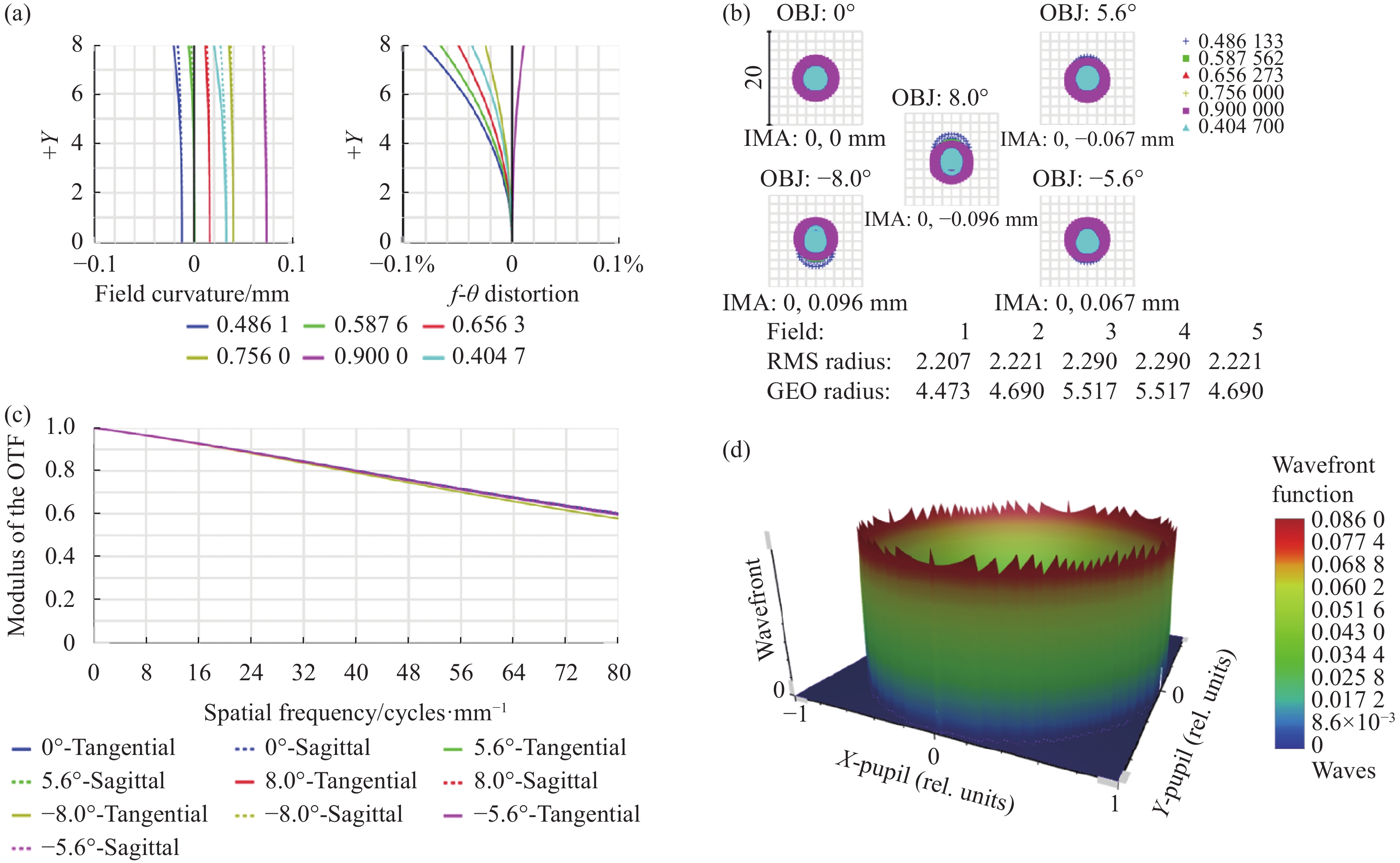
图8为最边缘子眼的模拟结果。图8(a)为最边缘子眼在ω=40°(即子眼透镜偏向光中继系统光轴的夹角为40°)的场曲畸变曲线图。可以看出,最边缘子眼场曲小于0.2 mm,畸变控制在2%以内。图8(b)为最边缘子眼的点列图,不同视场下的RMS值分别为3.106、2.693、2.694、3.699、3.686 μm,艾里斑半径为4.606 μm,RMS值均在艾里斑半径内。最边缘子眼的MTF曲线图如图8(c)所示,可以看出在80 lp/mm的奈奎斯特频率下,MTF值高于0.4且曲线平滑,表明在边缘视场也可以获得较好的成像质量。图8(d)为最边缘子眼的波前图,可以看出波峰到波谷为0.424λ,说明最边缘子眼产生的最大光程差得到了很好的校正。
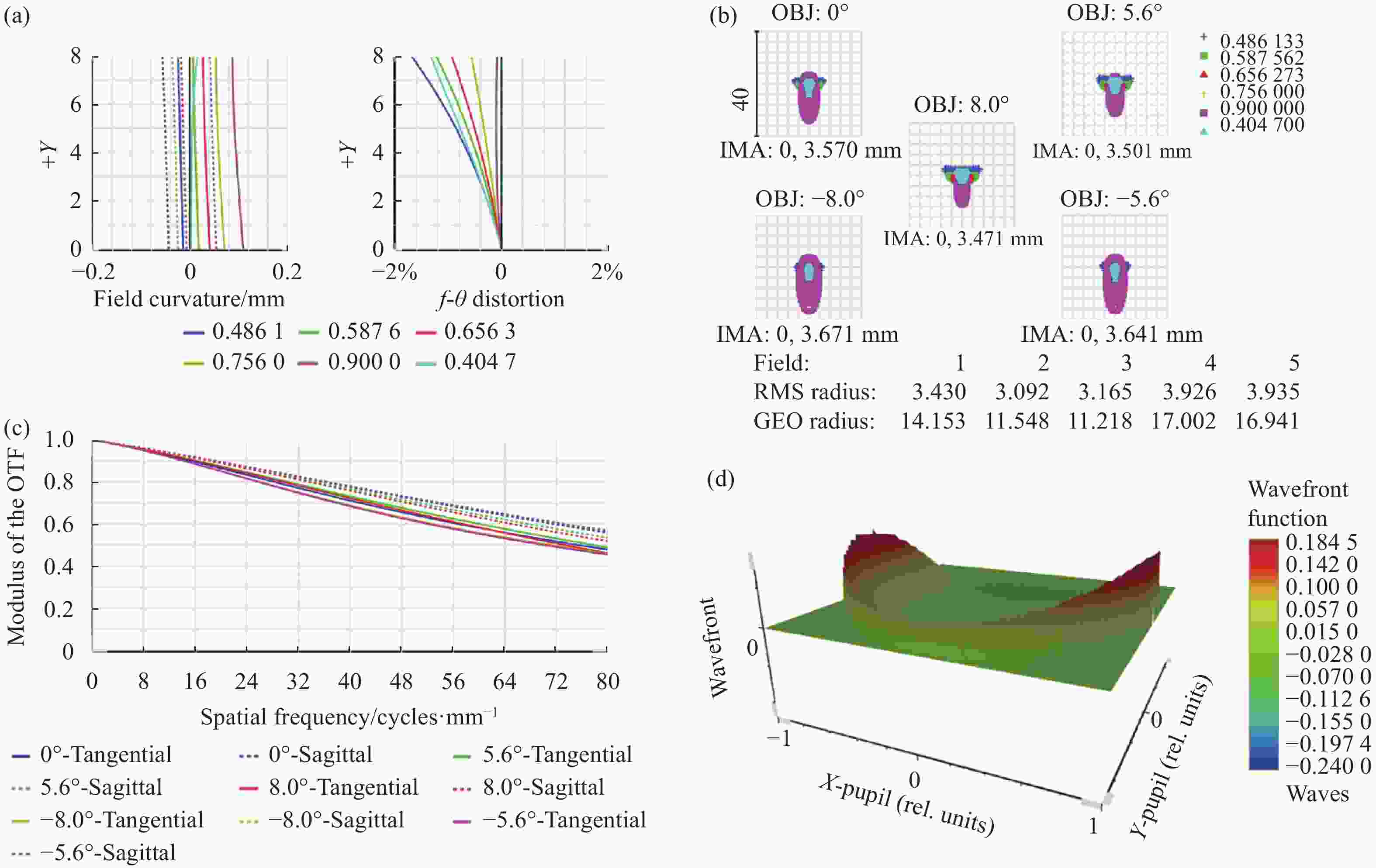
Figure 8. Simulation results for the ommatidium at the extreme edge. (a) Curvature distortion; (b) Spot diagram; (c) MTF; (d) Wavefront
-
针对现有复眼拼接中继系统设计难度大的问题,提出了一种平像面拼接的方法,并且对该方法进行了数学描述。通过构建子眼个数、系统总视场角以及后续光中继系统参数选取之间的平衡模型,分析出该拼接方法造成的光程差通常在中继系统可接受的景深范畴内,证明可以有效地降低后续光中继系统的设计难度。基于该方法设计的大视场复眼光学系统进行实践验证,结果证明了该方法理论可行。
Large field of view flat image plane splicing method for compound eye systems
doi: 10.3788/IRLA20210848
- Received Date: 2021-11-12
- Rev Recd Date: 2021-12-21
- Publish Date: 2022-08-05
Fund Project:
Science and Technology Development Plan of Jilin Province(20190302098 G)
-
Key words:
- optical systems design /
- bionic compound eye system /
- flat plane splicing /
- curved plane splicing
Abstract: The conventional curved bionic compound eye relay system is required to undertake the task of converting the curved image plane caused by the splicing of large-field subeyes into a flat image field, which poses certain difficulties to the system design. A method was proposed for the splicing arrangement of the flat image plane of the large-field compound eyes, and the method was described mathematically. By constructing a balanced model between the number of subeyes, the total field of view of the system and the subsequent reasonable selection of the optical relay system parameters, the relationship between the depth of field of the relay system and the optical range difference of the spliced image plane of the compound eye was analysed, and it was concluded that the optical range difference generated by the splicing method of the compound eye flat image plane was within the acceptable depth of field of a typical optical relay system, which could effectively reduce the design pressure of the relay optical system. Based on the above theory, a compound eye optical system with a field of view of 16° for a single subeye and an overall field of view of 96° was designed for practical verification. The system finally achieves an aberration of less than 2%, the transfer function reaches the diffraction limit in the central field of view and the edge field of view is close to the diffraction limit with good image quality, which proves that splicing theory is feasible.


 DownLoad: