


-
随着我国工业制造的快速发展和对“质量为先”的贯彻落实,通过先进的三维测量技术实现对工业产品的全尺寸和表面缺陷等高精度高效率的在线检测显得十分重要。传统接触式三维测量技术:包括人工测量与三坐标测量仪。这些方法测量效率较低,会造成被测物一定程度的损伤,同时只适用于离线测量,无法满足高精度、高效率、无损害的在线检测需求。随着计算机与相机性能的快速提升和机器视觉技术的飞速发展,非接触式的三维视觉测量技术得到广泛应用,由于其测量精度高、测量效率快且不会损坏被测物表面的优势而在工业生产质量检测中表现出色。
非接触式三维视觉测量方法可以分类为主动式测量和被动式测量,基于机器视觉的被动式三维测量技术则依赖图像特征匹配算法,不适用于缺少表面特征的工业产品三维测量。面结构光三维视觉测量方法虽然测量精度较高,但易受测量环境和被测物表面性质的影响,工业测量应用受限。以基于线结构光的主动式三维视觉测量技术为代表,其简单通用的激光三角测量结构、较强的抗干扰能力和较高的测量精度可以实现高效在线的三维视觉测量[1-3]。基于上述情况,文中通过建立线结构光三维视觉测量数学模型和分析旋转扫描中心轴的标定方法,设计了基于线结构光旋转扫描的三维视觉测量方案。该测量方案由线结构光旋转扫描视觉子系统和计算控制子系统构成,通过线激光旋转扫描视觉子系统扫描被测件全部轮廓并采集投射在被测表面的光条纹图像,计算控制子系统负责线结构光旋转扫描视觉子系统的标定、相机采集与旋转扫描的控制信号传输、光条纹图像处理与重建点云数据。针对光条纹灰度较低而导致光条纹中心线数据缺失的情况,提出了基于缺失区域灰度自适应增强的光条纹中心线提取算法,可以有效完整地提取线结构光投影条纹中心线,修复外轮廓点云数据。通过标准球棒的三维测量精度评价实验验证了文中的三维视觉测量方案测量精度较高,并应用于金属轮毂外轮廓形貌三维测量,可以有效实现金属零部件高精度无损害且稳定的在线三维检测,利用轮毂外轮廓最大半径重复实验验证了方案的可重复性,对国内工业制造的质量检测研究具有参考价值。
-
建立以相机针孔模型和线结构光平面方程构建的线结构光三维视觉测量模型[4],如图1所示。
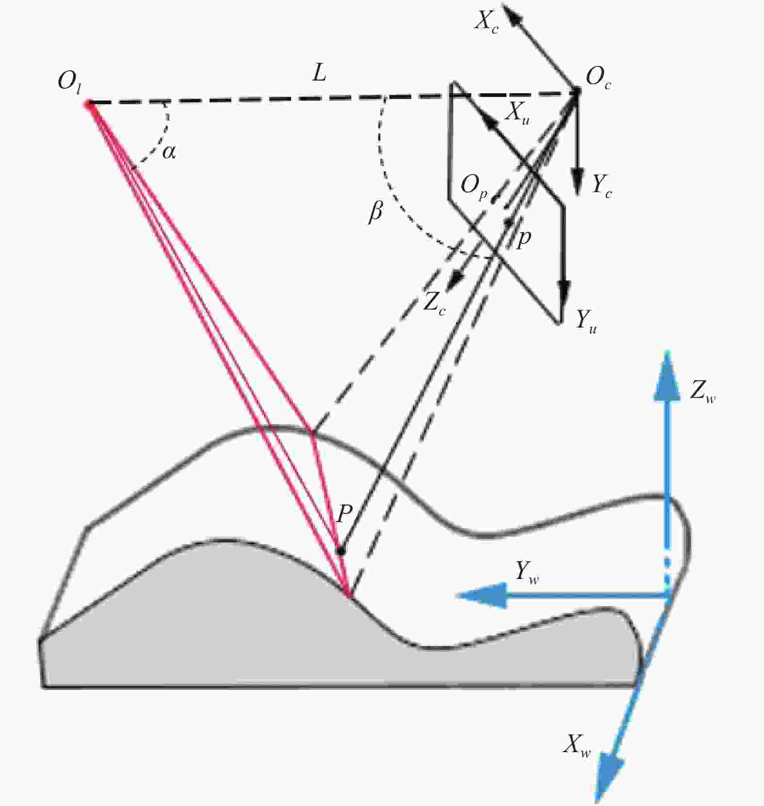
Figure 1. Mathematical model of line structured light 3-D vision measurement
Oc为相机光心,以此为原点建立相机坐标系(Oc-XcYcZc),相机成像平面上分别建立了理想图像坐标系(Ou-XuYu)和像素坐标系(o’- uv),并在被测物处建立世界坐标系(Ow-XwYwZw)。线激光发生器Ol产生的线结构光投射到被测物表面,相机采集受被测表面形貌调制而产生变形的光条纹图像。点P为被测物表面一投影点,在成像平面上的像点为P点。针孔模型下,成像平面上的坐标点与空间坐标系中对应点呈线性关系,利用简单的几何关系建立点P的像素坐标(u , v)和世界坐标系下三维坐标(Xw ,Yw ,Zw)之间的映射关系:
令${k}_{x}=\dfrac{f}{{\rm{d}}x},{k}_{y}=\dfrac{f}{{\rm{d}}y}$,其中f为焦距,dx和dy分别为成像平面x、 y方向上一个像素的单位物理尺寸,u0、v0则为图像坐标系原点相对像素坐标系原点的偏移像素值,s为尺度因子。文中采用基于平面模板的张正友标定法[5]求解相机模型,得到由kx、k y、u0和v0构成的相机内部参数与畸变系数。而旋转矩阵R和平移向量T构成的外部参数矩阵描述了世界坐标系相对相机坐标系的位姿关系,可借助相机标定结果计算获得。
显然,已知相机模型后可以获得经过相机光心Oc和投影点P的空间直线方程,再利用线结构光平面方程作为几何约束条件,就可以进一步确定被测表面光条纹投影点P的三维信息。
线结构光平面在相机坐标系中的平面方程可表示为:
投影点P的图像坐标为(xP, yP, zP),由公式(1)相机模型可以确认光条投影点与相机光心构成的射线方程:
由公式(2)和公式(3)两者构成的线面模型可以确认线结构光投影点的唯一三维坐标信息。
-
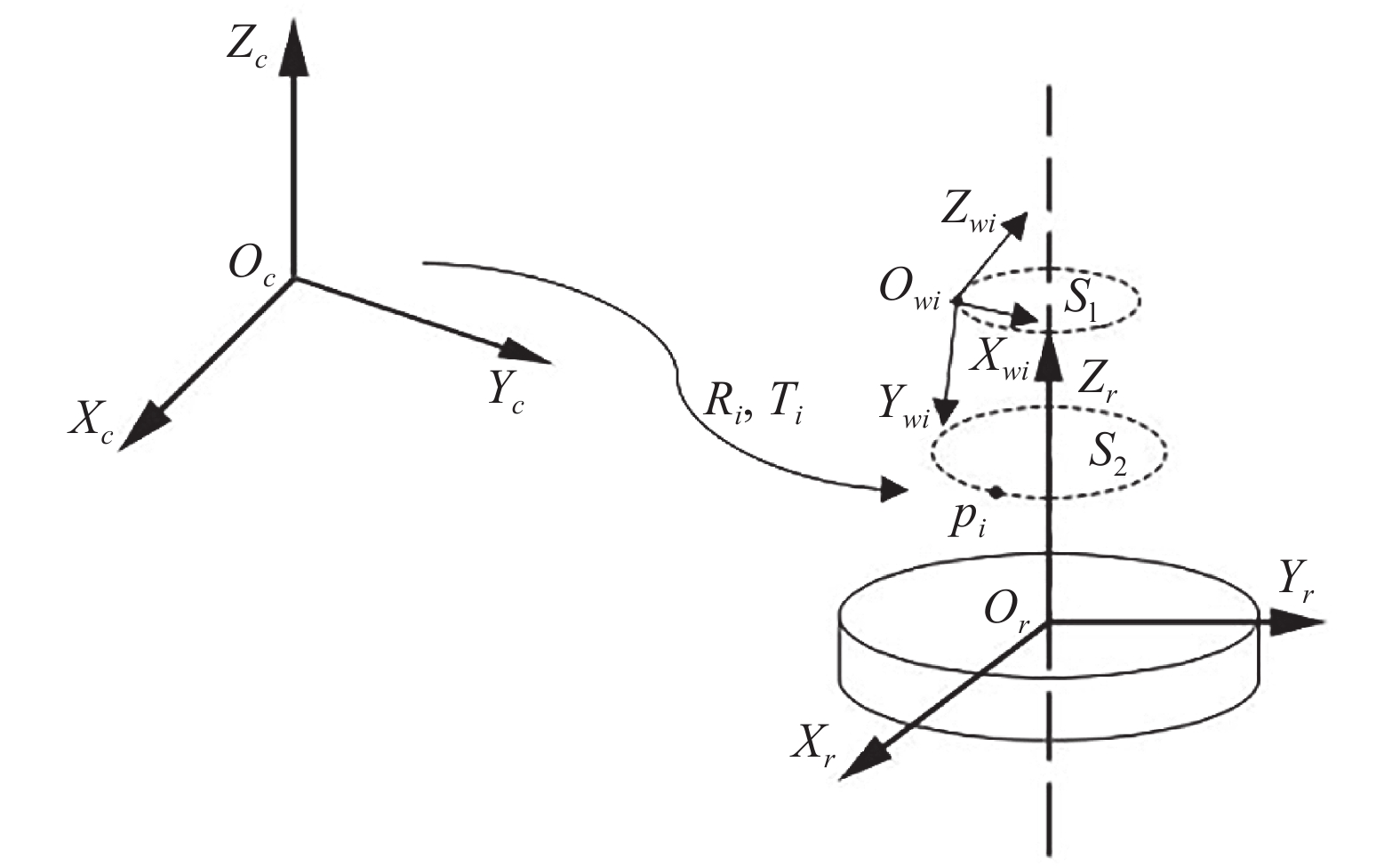
为实现沿旋转扫描方向对被测物外轮廓进行三维重建,还需要进一步标定旋转扫描中心轴相对相机与线结构光平面的空间位置。文中采用基于平面模板的旋转中心轴标定方法,将平面模板置于旋转台上,表面任意特征点P(P1, P2, …, Pi)随着旋转台旋转运动,其运动轨迹均为以旋转台中心轴为旋转轴的空间圆,运动轨迹点均处于平面S(S1, S2,…, Si)内,[Ri, Ti]为平面模型上建立的世界坐标系相对相机坐标系的位姿参数,旋转扫描中心轴标定原理如图2所示。

Figure 2. Schematic diagram of rotating scan center axis calibration
依据上述P点旋转运动轨迹规律,通过获取多个圆运动轨迹上点的相机坐标系下位置,则可以通过拟合圆得到每个运动轨迹圆的圆心三维坐标,进一步地,可以利用所有圆心坐标点来拟合旋转扫描中心轴直线方程。
但为方便后续测量目标计算,文中在旋转平台上建立旋转台坐标系(Or-XrYrZr),旋转台坐标系的Zr轴即为旋转扫描的中心轴,在相机坐标系下可用向量zr表示。利用平面模板放置于旋转台表面,模板平面与旋转轴的交点设为旋转台坐标系原点Or,设定一过原点且垂直于旋转轴的直线的方向向量xr为旋转台坐标系的Xr轴,利用三维坐标系的性质可以确定旋转台坐标系的Yr轴在相机坐标系下的向量yr=zr×xr。则由旋转台坐标系变换到相机坐标系的旋转矩阵可表示为:
依据旋转矩阵的单位正交矩阵性质,相机坐标系到旋转台坐标系的旋转矩阵${{r}}_{{r}{x}}^{{c}{x}}$${R}_{c\to r}={R}_{r\to c}^{{\rm{{T}}}}$,在已知Oc与Or相对位置的情况下即可知道相机坐标系到旋转台坐标系的平移向量$ {T}_{c\to r} $。
-
目前光条纹中心线提取算法的相关研究有很多,包括灰度重心法、Steger算法、高斯拟合算法等[6-10],在文中金属零部件三维测量的应用环境下,采集到的线结构光投影条纹图像往往受到金属零部件表面特性影响导致光条纹灰度值分布不均且灰度值较低的情况,经过中值滤波、阈值化和形态学处理等的图像预处理后光条纹较暗的区域极易分割为背景,使得前景区域的光条纹部分数据缺失。文中针对该应用背景和存在的问题,依据灰度重心法原理简单、计算量小的特点,提出了基于缺失区域自适应灰度增强的光条纹中心线提取方法。
灰度重心法利用光条纹灰度值呈高斯分布的特征,计算行/列方向的灰度重心坐标,计算公式为:
式中:fij表示输入图像i行j列的像素点灰度值;xi和yi分别表示横坐标i和纵坐标j; $ \stackrel{-}{x} $0或$ \stackrel{-}{y} $0为计算结果第j0列/第i0行的灰度重心坐标。
文中基于缺失区域自适应灰度增强的光条纹中心线提取算法流程图如图3所示。对原始灰度图进行图像预处理和灰度重心法初步提取光条纹中心线,如图4(b1)、(b2)所示。光条纹的综合宽度W计算见公式(6):

Figure 3. Algorithm flow chart of extracting laser stripe centerline in this paper

Figure 4. Laser stripe centerline extraction algorithm in this paper. (a1), (a2) Gray-scale image of laser stripe on the welding seam of a metal hub; (b1), (b2) Preliminary gray centroid method to extract the centerline of laser stripe; (c1), (c2) Frame selection of missing segments; (d1), (d2) Adaptive gray-scale enhancement to repair missing segments; (e1), (e2) Gray centroid method to completely extract the centerline of laser stripe
式中:w(i)表示第i列灰度值大于0的像素数,通过计算线结构光条纹N列w(i)的均值获取W。
初步光条纹中心线提取后若有数据缺失段则找到缺失段的两端点PLi(xli,yri)和PRi(xri,yri),进而可以对相对原始图像原点的偏移量为(xli −1, min(yri,yri)−M/2)、尺寸为(xri −xli−1)×(|yri − yli|+M)的感兴趣区域进行框选,如图4(c1)、(c2)所示。对框选区域的灰度图像阈值分割出前景区域即缺失的光条纹区域,计算前景区域的平均灰度值Gavg并获得灰度增强系数h,如公式(7)所示:
式中:Nfg为前景区域的像素数量;g(xi,yi)是前景区域第i个像素点的灰度值。对光条纹灰度图像中缺失区域像素点通过自适应灰度增强系数h修复缺失区域。g’(xi,yi)是缺失段ROI前景区域灰度增强后的像素点(xi,yi)灰度值,可表示为:
光条缺失段修复效果见图4(d1)、(d2)。最后再次利用灰度重心法提取完整的光条纹中心线,基于缺失区域自适应灰度增强的光条纹中心线提取效果见图4(e1)、(e2),可见缺失区域的光条纹得到有效修复。
-
文中设计的基于线结构光旋转扫描的三维视觉测量方案包括线结构光旋转扫描视觉子系统和计算控制子系统。线结构光旋转扫描视觉子系统包括视觉模块和旋转台,其中视觉模块由工业相机和线激光发生器构成,负责采集被测物表面的线结构光投影条纹图像;旋转台带动静置在其上的被测物运动,保证线结构光完整扫描被测物表面。计算控制子系统主要负责控制信号的传输与数据计算。计算控制子系统中处理器产生的控制信号来准确控制线激光发生器状态、相机采集状态和旋转扫描控制器状态,并且将接收到的图像数据来计算视觉系统的标定结果,基于缺失区域自适应灰度增强的光条纹中心线提取并重建三维点云数据。文中的三维视觉测量方案见图5。

Figure 5. 3-D vision measurement scheme in this paper
文中的三维视觉测量步骤见图6。

Figure 6. 3-D vision measurement steps based on line structured light rotation scanning
-
实验平台采用650 nm的线激光发生器、Daheng MER2-503-36 U3 M的工业相机和型号GCD-0401 M、控制旋转精度为0.001 °旋转台控制器。实验处理器配置为英特尔Core i5-10210 U CPU@1.60 GHz、四核、内存8 G,软件开发平台为Visual Studio 2019,OpenCV 4.0.0和PCL1.11.0。在标定视觉模块后(标定结果见表1)[11-12],以哑光陶瓷标准球棒和金属轮毂为被测物分别进行三维测量。
Parameter name Calibration results
Camera internal parameters$ \left[ {\begin{array}{*{20}{c}} {{\text{3\;553}}{\text{.406\;333}}}&{\text{0}}&{{\text{1\;251}}{\text{.233\;369}}} \\ {\text{0}}&{{\text{3\;556}}{\text{.068\;465}}}&{{\text{1\;020}}{\text{.443\;882}}} \\ {\text{0}}&{\text{0}}&{\text{1}} \end{array}} \right] $ Distortion coefficient [0.107 913 1.088 657 0.000 477 0.000 105 −7.125 999] Optical plane equation $ - {\text{0}}{\text{.053\;813\;3}}{x_c} + {\text{0}}{\text{.829\;647}}{y_c} + {\text{0}}{\text{.555\;689}}{z_c} - 93.540\;8 = 0 $ Rotation axis equation $\dfrac{{{x_c} - {\text{4}}{\text{.388\;52}}}}{{{\text{0}}{\text{.998\;333}}}} = \dfrac{{{y_c} + {\text{56}}{\text{.862\;8}}}}{{{\text{ 0}}{\text{.0289\;22}}}} = \dfrac{{{z_c} - {\text{263}}{\text{.342}}}}{{{\text{0}}{\text{.0499\;468}}}}$ Table 1. Vision module calibration parameters
-
通过对哑光陶瓷标准球棒进行线激光旋转扫描来重建球棒表面点云数据,通过最小二乘法拟合球方程进而计算标准球棒A,B两球的球半径和球心距,10组重复测量结果见表2。
Test groups A
diameter/mmB
diameter/mmSphere center distance between
A & B/mm1 25.471 2 25.475 8 100.046 2 2 25.459 2 25.473 0 100.051 7 3 25.444 8 25.475 8 100.083 0 4 25.459 2 25.475 4 100.073 5 5 25.440 8 25.481 8 100.039 2 6 25.446 8 25.342 8 100.021 3 7 25.379 2 25.467 2 100.076 2 8 25.386 1 25.458 7 100.062 3 9 25.462 5 25.461 7 100.057 6 10 25.458 0 25.358 2 100.044 5 Standard value 25.411 0 25.413 6 100.001 1 Maximum deviation 0.060 2 0.068 2 0.081 9 Standard deviation 0.042 5 0.058 9 0.057 9 Table 2. Standard bat measurement results
在相同实验环境下10组的测量结果有一定的波动,但总体的测量系统精度误差在±0.06 mm内。误差产生的原因除了线结构光旋转扫描视觉系统的标定带来的误差,还因为标准球棒表面线结构光散射较多,投影条纹宽度不一,导致线结构光投影条纹中心线提取不准确,造成后续三维点云重建产生偏差。但综合以上测量系统精度评价实验结果的分析,可知文中测量方案的测量精度较高,满足测量精度要求。
-
被测物金属轮毂是个高80 mm,最宽直径277 mm的旋转体。金属轮毂中部围绕了一圈宽度约7 mm的焊缝区域。实验目标是测量轮毂焊缝区域的外轮廓形貌和不同扫描角度下的最大半径值。被测金属轮毂实物图和实验图见图7。

Figure 7. (a) Physical drawing of measured metal hub; (b) Experimental diagram
将被测轮毂放置于旋转台上,以单位旋转角度0.307°进行扫描,共采集1172张线结构光投影条纹图像,分别利用文中提出的基于缺失区域自适应灰度增强的光条纹中心线提取方法和灰度重心法提取中心线,通过视觉模块和旋转扫描中心轴的标定结果对轮毂外轮廓形貌进行测量,重建效果见图8。由图8可以清晰的看到文中提出的基于缺失区域自适应灰度增强的光条纹中心线提取算法有效地修复了光条纹缺失区域,重建点云数量增加了969个,有效提高了点云完整性。

Figure 8. 3-D contour reconstruction renderings of the wheel hub
在相同实验环境下,对同一轮毂进行5组外轮廓形貌测量重复性实验,计算不同旋转扫描角度下的轮毂外轮廓最大半径值。重复测量结果如图9所示,可以直观看到每组轮毂外轮廓最大半径随扫描角度的变化和分布趋势一致。

Figure 9. Repeated measurement results of the maximum radius of the outer contour of the hub
通过计算每个扫描角度下5组轮毂最大半径测量值的标准差σ,并用$ \delta =\sigma /\stackrel{-}{r} $来表示轮毂外轮廓最大半径测量的重复性误差,其中$ \stackrel{-}{r} $为多次测量的平均值,显然$ \delta $越小测量重复性越高。测量重复性误差结果见图10。

Figure 10. Repeatability error of the maximum radius of the outer contour of the hub
轮毂外轮廓不同扫描位置下的最大半径测量重复性误差均优于0.3%,最大值为128.019°处的重复性误差0.2743%。综上说明文中基于线结构光旋转扫描的三维视觉测量方案在轮毂外轮廓形貌测量应用中可重复性较高。
-
在工业制造产品检测应用场景中,针对接触式的三维测量方式无法快速高精度且无损害地测量工业产品三维尺寸,文中进行了基于线结构光旋转扫描和光条纹修复的三维视觉测量技术的研究。通过分析线结构光三维视觉测量数学模型和旋转扫描中心轴的标定原理,实现被测点在旋转台坐标系中的重建;并提出了基于缺失区域自适应灰度增强的光条纹中心线提取算法,解决了光条纹低灰度区域数据缺失的问题,提高了被测零部件点云数据完整性;通过重建标准球棒的表面点云,计算两球直径与球间距,得到文中基于线结构光旋转扫描的测量系统的测量精度优于0.06 mm。文中的三维视觉测量方案应用于金属轮毂外轮廓形貌测量,可以有效测量轮毂的表面轮廓和各角度下最大半径值,通过轮毂外轮廓最大半径重复性测量实验,可得测量系统重复性误差优于0.03%。文中提出的基于线结构光旋转扫描和光条纹修复的三维视觉测量方案对工业制造的质量检测研究具有参考价值。
Research on 3-D vision measurement technology based on line structured light rotating scanning and laser stripe repair
doi: 10.3788/IRLA20210894
- Received Date: 2021-12-01
- Rev Recd Date: 2022-01-10
- Available Online: 2022-03-04
- Publish Date: 2022-02-28
-
Key words:
- 3-D vision measurement /
- line structured light /
- calibration
Abstract: Non-contact 3-D vision measurement is widely used in industrial manufacturing quality inspection. Aiming at the application scenario of industrial metal parts detection, a 3-D vision measurement scheme based on line structured light rotating scanning and laser stripe repair was proposed. Firstly, through the computer vision technology based on line structured light projection, the line structured light rotating scanning vision subsystem was designed, and the industrial camera, line structured light plane and rotating scanning central axis were calibrated; Then, aiming at the problem of missing data in the low gray area of the collected laser stripe image, a laser stripe center line extraction algorithm based on adaptive gray enhancement of the missing area was proposed, which effectively repaired the line structured light projection stripes of the tested parts; At the same time, using the line structured light 3-D vision measurement scheme proposed in this paper, the accuracy of the measurement system was evaluated by reconstructing the surface point cloud of the standard bat and calculating the diameter and spacing of the two balls. The accuracy of the measurement system was better than 0.06 mm; Finally, the shape of the outer contour of the metal hub was measured, and the maximum radius of the outer contour of the hub was calculated through the repeatability experiment. It is verified that the repeatability error is better than 0.03%. The experimental results show that this method can realize the 3-D measurement of industrial metal parts without damage, high efficiency and high precision, and make up for the defects of the contact 3-D measurement method.


 DownLoad: