


-
微透镜阵列是一系列微米级至毫米级孔径尺寸的透镜按照一定的排列形成的阵列。相较于传统的单透镜,微透镜阵列具有高并行性,每个单元都能独立完成各项功能。微透镜阵列在光场成像[1-2]、光束匀化[3]、集成成像[4]、LED相关色温调节[5]等方面有广泛应用。然而,传统的定焦微透镜阵列却无法在一些可变焦距或宽视场的应用中发挥作用。采用微流体操控技术制备的微透镜阵列以其灵活的可调控性、制造工艺简便性、制造成本低廉等优点在微透镜制造领域一直是研究热点。其形成原理是微流体克服薄膜张力使薄膜表面发生凸起形变,从而形成微透镜阵列,微透镜阵列表面曲率由注入的微流体体积控制。目前,根据控制条件的不同,这种焦距可调的微透镜阵列主要被分为以下几种:驱动电压控制的电湿润效应的可变焦透镜阵列[6-8]、电压控制的聚合物分散液晶的可变焦透镜阵列[9-10]以及液压控制的充液型可变焦透镜阵列[11-12]。相较于电压控制的微透镜阵列,充液型微透镜阵列可实现液压调节、液体粘稠度调节等多方式调节。
近年来,液体可调焦微透镜阵列通常采用聚二甲基硅氧烷(PDMS)薄膜作为塑形材料[13-14]。但由于其无粘合性,需要利用键合技术将其与基片贴合。而光学胶膜(OCA)作为触摸屏的重要组成部分,具有良好的弹性、粘性(泊松比0.3,杨氏模量58 kPa)以及可见光范围高透光率(达到99%以上)等特性。薄膜本身还具有易于加工、成本低的特点,并且便于大量生产。相较于PDMS薄膜,由于其自身粘性较强,可以直接与基片贴合从而提升制作效率。由此,笔者利用OCA薄膜、微孔硅片阵列、基板玻璃、去离子水等材料设计了一种液体可变焦平凸微透镜阵列。
-
液体可变焦微透镜阵列结构与形成原理如图1所示,OCA薄膜粘附于具有矩形排布微孔的硅片上,玻璃基底、玻璃支撑与硅片组成微流体腔。微流体腔两侧分别设有毛细管作为微流体通道,用于空气的排出和液体的注入。未注入液体前,微流体腔内的气压与外界大气压保持一致,薄膜两侧压强相等,此时薄膜不发生形变,如图1(a)所示。利用注射器注入去离子水,待微流体腔内气体排净后,密封出口。继续注入一定体积的去离子水,此时OCA薄膜两侧形成压强差,并发生一定程度的形变,形成平凸透镜,如图1(b)所示。通过调控薄膜形变量可以实现微透镜阵列的变焦。

Figure 1. Schematic diagram of tunable-focus liquid microlens array. (a) Before the water injection; (b) After the water injection
-
(1) 微孔阵列制作:采用厚度为0.2 mm的硅片作为基材,利用飞秒激光打孔技术在该硅片上雕刻3×3(单个孔径为500 μm)的微孔阵列。飞秒激光波长为515 nm,单脉冲能量为120 μJ。获得的微孔阵列典型光学显微镜图如图2所示,各微孔均匀性较好,无崩边。

Figure 2. Optical microscope image of the silicon micro-holes array
(2) OCA薄膜固定:为了清除激光打孔后孔壁残余氧化物,先将步骤(1)中制作完成的微孔阵列置于5%的氢氟酸中浸泡10 min,再用去离子水超声波清洗10 min,然后将清洗完成的样品取出吹干,最后将样品平放至实验台,将OCA薄膜(厚度为100 μm)平铺至硅片上并完全覆盖微孔阵列区域,均匀按压,使其完全粘附,如图3(b)所示。

Figure 3. Flow chart of microlens array fabrication
(3) 微流体通道制作:如图3(c)所示,一块面积为2 cm×2 cm、厚度为1.1 mm的玻璃作为基底,四块厚度为0.6 mm的矩形玻璃作为支撑,内壁两侧预留宽度0.6 mm微孔通道放置毛细管(内径为0.3 mm),利用紫外光学胶将毛细管密封到微孔通道中,制成微流体通道。
(4) 微流体腔制作:如图3(d)所示,将紫外光学胶均匀涂抹至图3(c)中玻璃支撑上表面,将步骤(2)中制得的结构以OCA胶面朝玻璃支撑上表面粘贴,并置于紫外光下照射20 min至紫外光学胶完全固化。
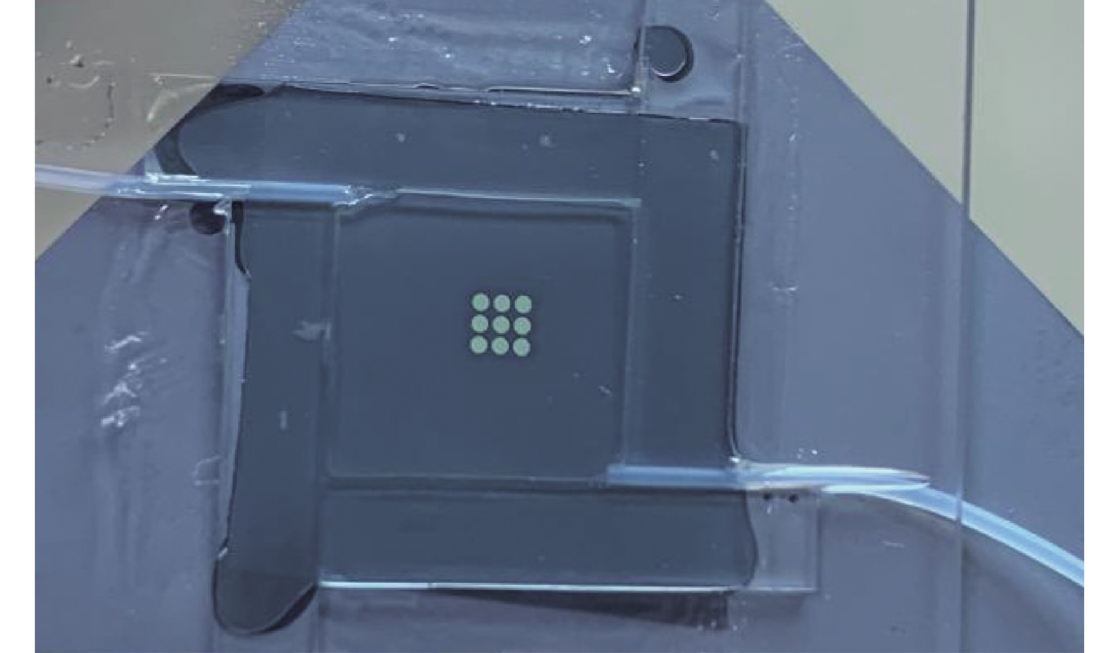
(5) 制作完成的可变焦液体微透镜阵列实物图如图4所示。

Figure 4. The picture of assembled tunable-focus liquid microlens array
-
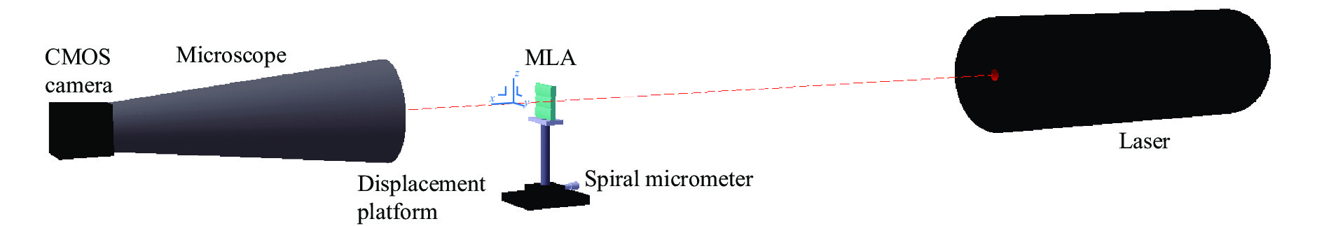
可调焦微透镜阵列焦距测量光路图如图5所示,红光激光(波长为650 nm)通过扩束后正入射至待测微透镜阵列玻璃基板,待测微透镜阵列放置在z轴可移动位移平台(带有螺旋测微仪)上,凸面朝向显微镜。固定微透镜阵列位置,将CMOS相机置于显微镜目镜端,调节显微镜物镜位置,当通过CMOS相机观察到OCA薄膜与硅片粘合处最清晰的像时,记录此时螺旋测微仪的值l1。固定显微镜位置不变,移动z轴可移动平台,通过CMOS相机观察到激光聚焦后光斑直径最小时的红点光斑,记录此时螺旋测微仪的值l2,OCA薄膜与硅片粘合表面位置至光斑直径最小时位置的距离视为焦距,此时焦距为l2与l1的差值。

Figure 5. Schematic diagram of focal length measurement
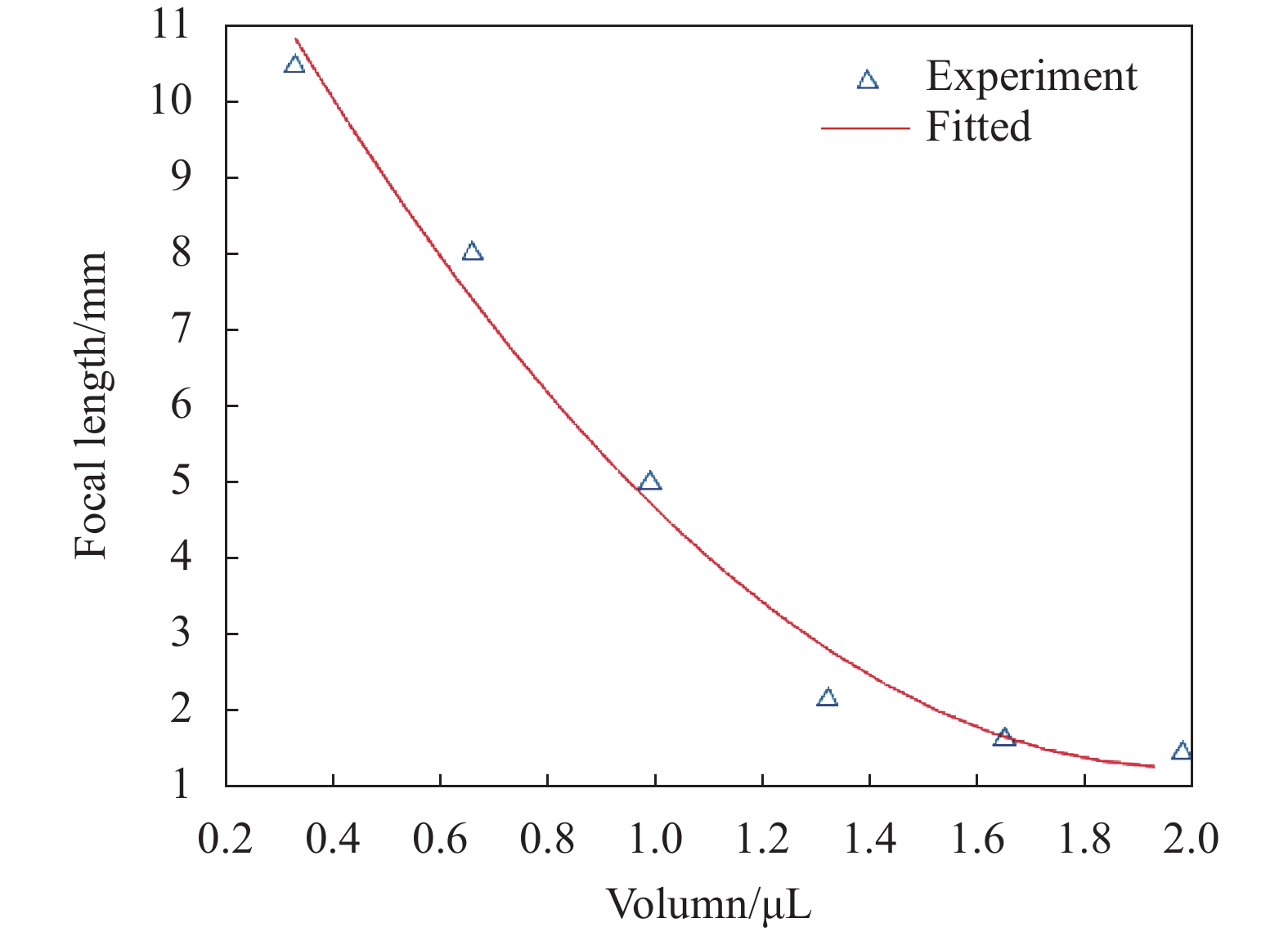
调节微透镜焦距时,首先将注射器固定在提拉仪上,设置提拉速度,使去离子水以10 μm/s的速度注满微流体腔,待腔内空气排净后,关闭出水口。之后,控制提拉仪提拉速度和时间,分六次逐次注入去离子水,每次分别注入0.33 μL,分别测量每次注水后微透镜阵列的焦距并记录聚焦光斑。其焦距与注水体积的关系如图6所示。微透镜阵列的焦距可以从1.46~10.44 mm调整,注水体积由0.33~1.98 μL调整,当注水体积到达1.98 μL后焦距基本保持不变,此时焦距值为1.46 mm。主要原因在于硅片具有一定厚度,去离子水注入微流体腔到达一定程度时靠近平面区域薄膜会沿着孔内壁向外形变,此时薄膜的形变程度已经达到最大值,凸起程度不发生变化。不同注水体积下激光聚焦光斑如图7所示。可以看出,各个微透镜阵列聚焦光斑比较均匀。图7(a)~(f)注入水的体积逐渐增加,激光聚焦光斑直径也逐渐降低,这是由于 OCA薄膜形变导致微透镜阵列焦距随注水体积增加而减小。

Figure 6. Relationship between water injection volume and focal distance
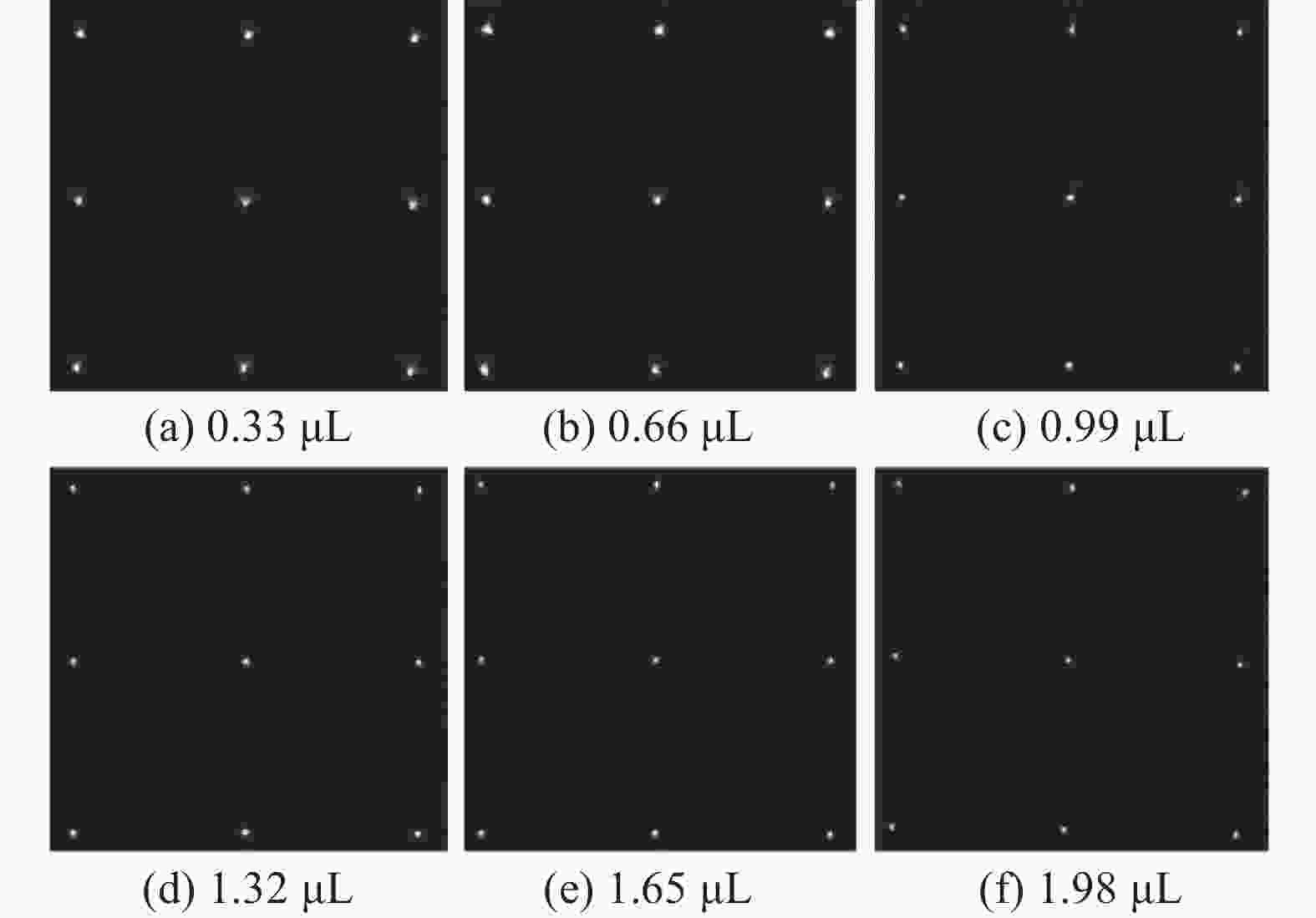
Figure 7. Laser spot focusing diagram of different water injection volume
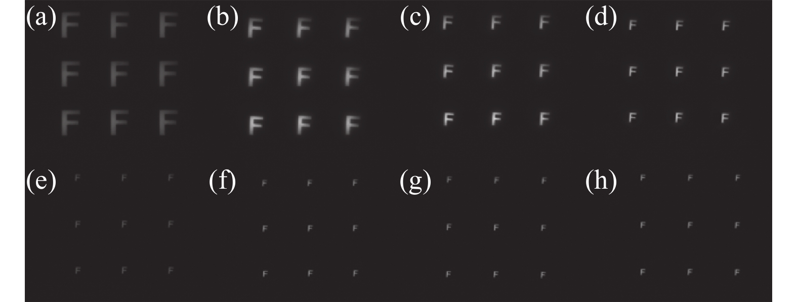
进一步对微透镜阵列进行了成像测试,实验光路如图8所示。采用白光LED作为光源,在LED前设置有匀光板,使LED光均匀照射一个中心镂空有一个“F”字母(尺寸为5 mm×3 mm)的矩形铝片掩模板。该字母作为物体,采用微透镜阵列对其成像。由于微透镜阵列焦距较短,物距较长,像距较短,为了使用CMOS相机记录所成的像,文中采用显微镜进行二次成像。将可调焦微透镜阵列、显微镜和CMOS相机同轴设置。显微镜分别采用×3物镜和×16目镜。固定物距,微调显微镜的位置,记录不同注水体积下成的像,如图9所示。
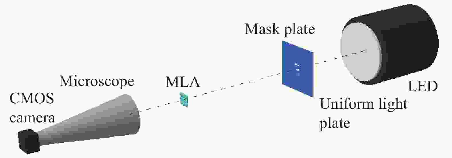
Figure 8. Imaging experimental diagram
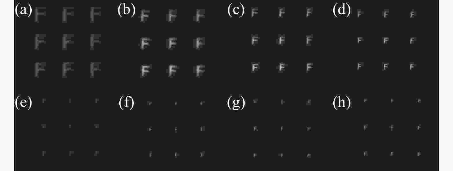
Figure 9. (a)-(h) Water injection volume 0.33,0.99,1.32,1.65,1.98,2.31,2.64 μL imaging diagram
由图9可见,在不同注水体积下,所成的像都表现出良好均匀性,进一步证实了微透镜阵列具有很好的均匀性。随着注水体积增加,微透镜阵列焦距减小,由高斯公式:
像距减小,垂轴放大率
$\;\beta = \dfrac{{l'}}{l}$ 也降低,因此,随着注水体积增大,成像尺寸逐渐降低。如图9(f)~(h)所示,当注水体积大于1.98 μL时,像的尺寸不再发生变化,主要原因是此时微透镜阵列焦距不再发生变化。 -
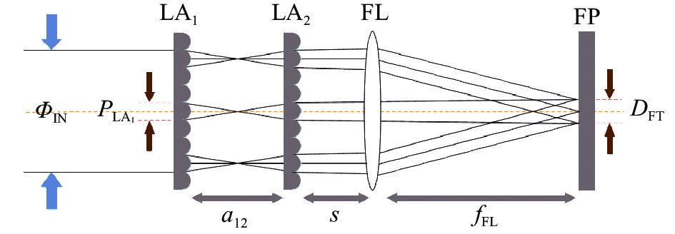
微透镜阵列在激光光束匀化整形中有着广泛的应用[15],激光光束匀化整形原理图如图10所示。

Figure 10. Principle diagram of laser beam homogenization and shaping
光通量为ΦIN的准直高斯光束分别通过第一组微透镜阵列LA1、第二组微透镜阵列LA2后被分割为若干束子光束,由傅里叶透镜FL对子光束聚焦,并在目标平面(FP)上叠加形成能量均匀的光斑。其中,a12为两透镜阵列间距,s为LA2与FL的间距,fFL为傅里叶透镜焦距。目标面上光斑尺寸为:
式中:
${P_{{\rm{L{A}}_1}}}$ 为单个透镜孔径;${f_{{\rm{FL}}}}$ 为傅里叶透镜焦距;${f_{{\rm{L{A}}_1}}}$ 与${f_{{\rm{L{A}}_2}}}$ 分别为LA1与LA2焦距,传统的定焦透镜阵列依据公式(2)中光斑尺寸约束条件,通过调节a12的大小,可以在目标平面上得到匀化光斑DFT。变焦透镜阵列则可以通过调整微透镜阵列的焦距方式实现光束匀化整形并且能实现匀化光斑可调。依据激光光束匀化整形约束条件公式(2)与微透镜阵列可调范围,确定参数如下:
${P_{{\rm{L{A}}_1}}}$ 为0.5 mm,${f_{{\rm{FL}}}}$ 为38.1 mm,a12为7.6 mm,s为13.74 mm。利用软件仿真确定可实现匀化的参数值,确定的两透镜阵列焦距可行范围为5.5~6.6 mm。依据仿真参数值进行实验,实验装置如图11所示,激光通过衰减器衰减后经过扩束镜扩束,并垂直入射两个同轴微透镜阵列。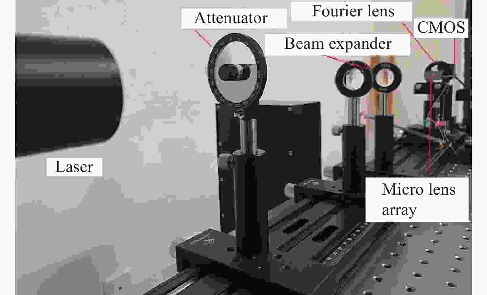
Figure 11. Experimental diagram
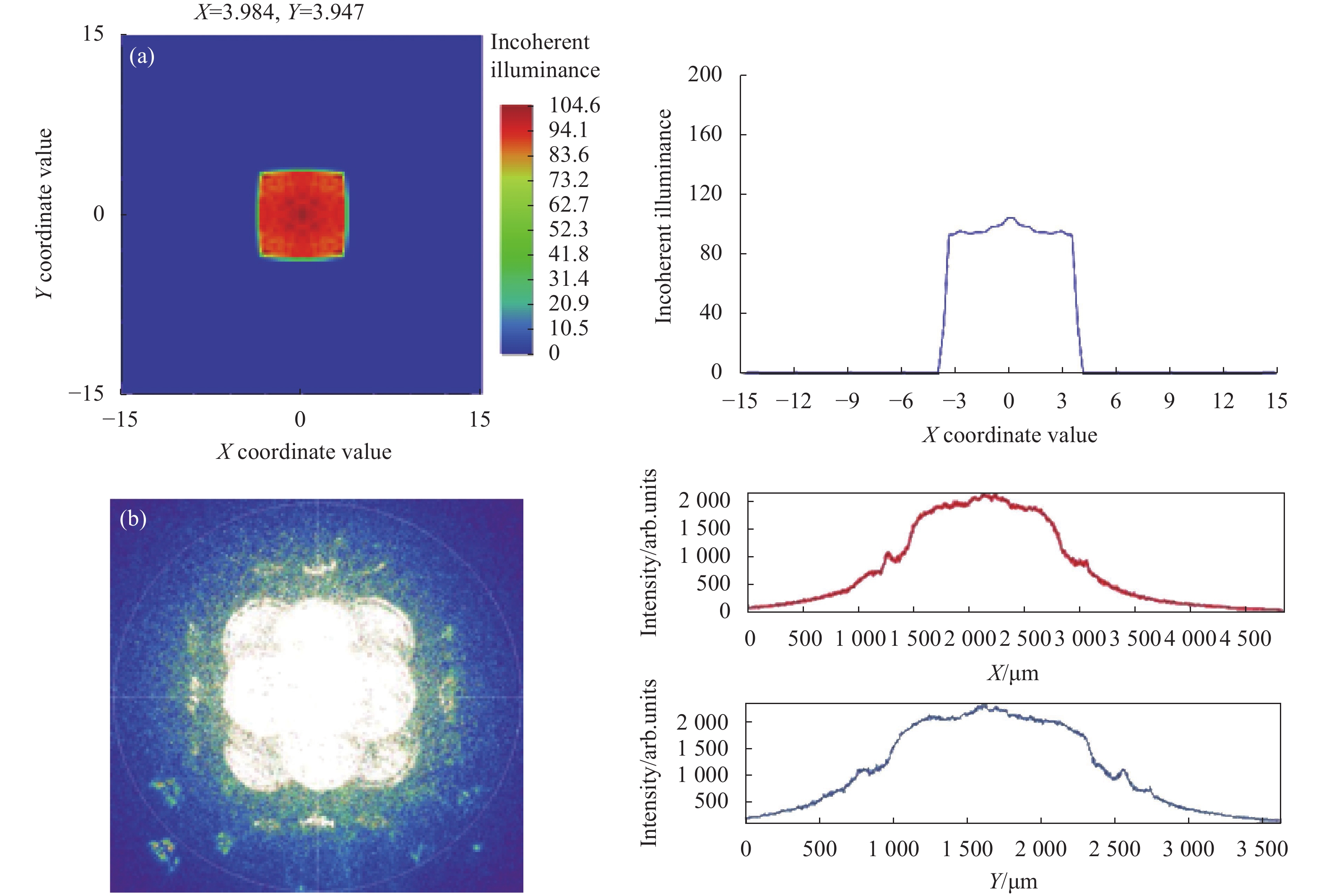
调节LA1与LA2的焦距大小,获得了几组可实现匀化的系统参数值。图12~14为实现激光光束匀化整形仿真图与对应的实验图,当
${f_{{\rm{L{A}}_2}}}$ 为5.5 mm、${f_{{\rm{L{A}}_1}}}$ 为6.5 mm时,得到第一组光斑尺寸为7.2 mm的矩形匀化光斑,如图12所示。可见光斑能量分布较为均匀,但是光斑四角处能量较中间区域更低。由于实验采用了3×3透镜阵列,透镜个数较少,限制了高斯光源分割数,影响了最终的匀化均匀性,可以通过增加微透镜阵列的子透镜个数改善均匀性。

Figure 12. (a) Simulation result when
${f_{{\rm{L{A}}_1}}}$ is 6.5 mm; (b) Experimental the result when${f_{{\rm{L{A}}_1}}}$ is 6.5 mm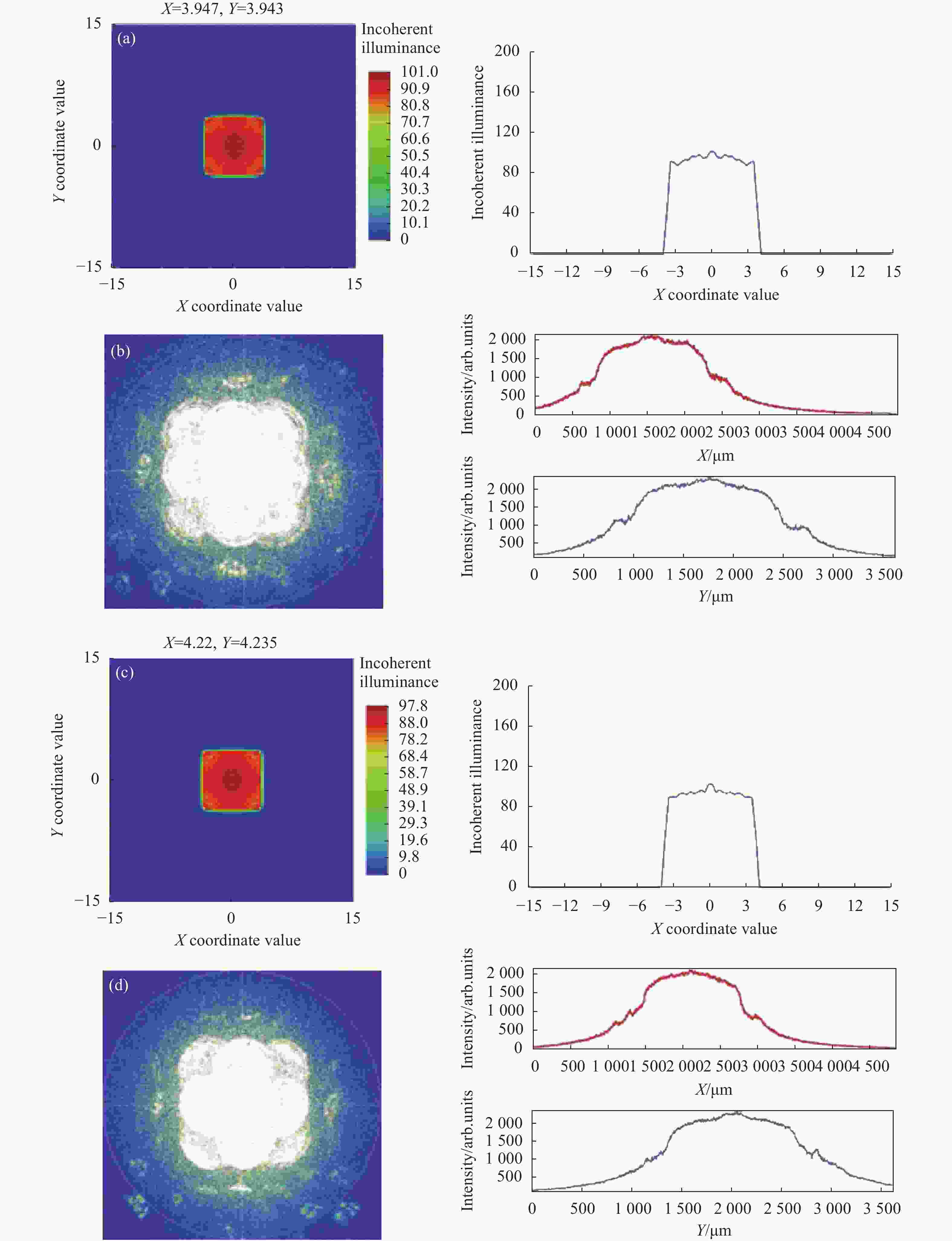
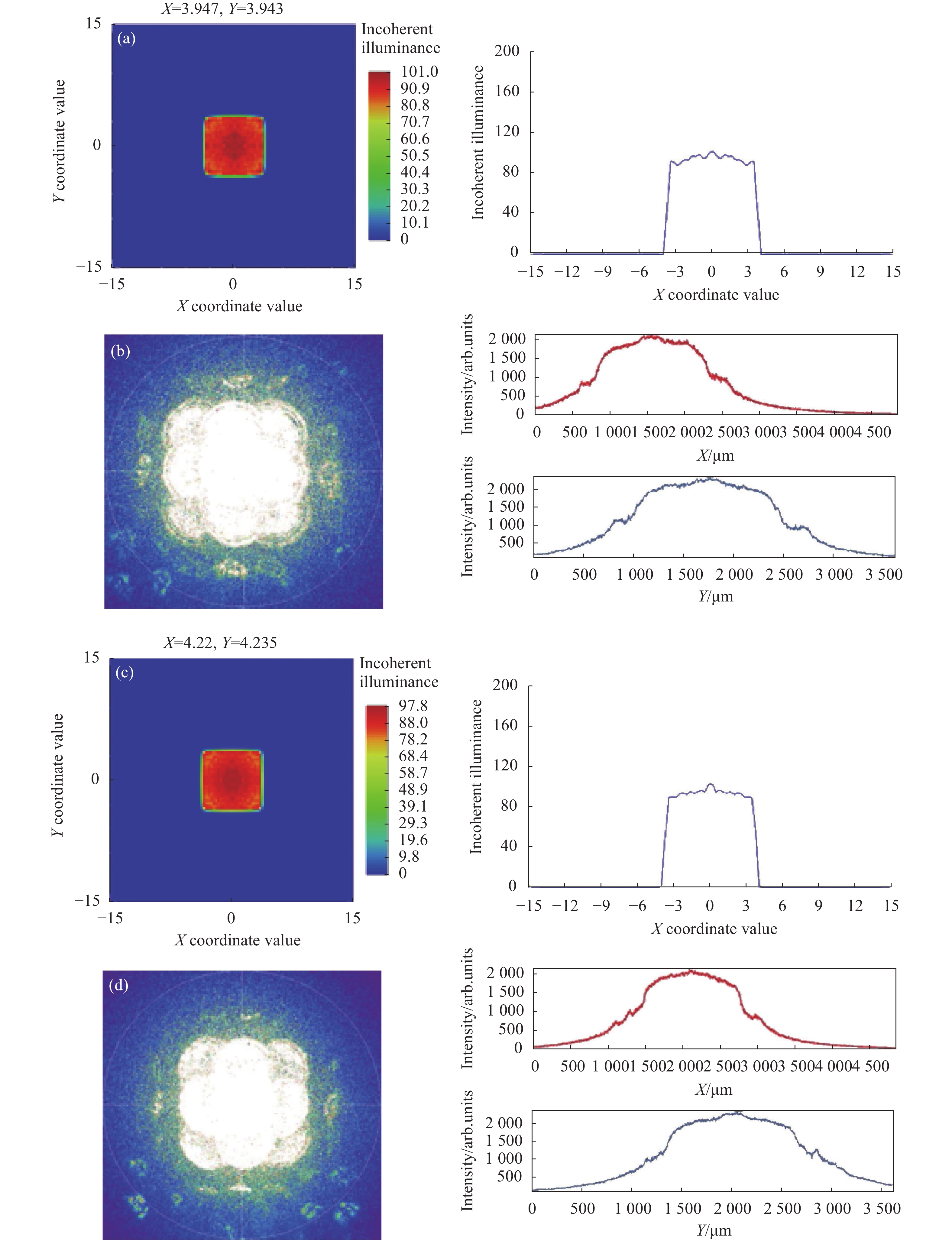
Figure 14. (a), (c) Simulation result graphics of the
${f_{{\rm{L{A}}_1}}}$ is 6.1 mm and 6.2 mm respectively; (b), (d) Experimental result graphics of the${f_{{\rm{L{A}}_1}}}$ is 6.1 mm and 6.2 mm respectively随着
${f_{{\rm{L{A}}_2}}}$ 增加,获取到第二组匀化光斑图,如图13所示。当${f_{{\rm{L{A}}_2}}}$ 为5.7 mm、${f_{{\rm{L{A}}_1}}}$ 为6.3 mm时,光束实现匀化整形且匀化光斑由7.2 mm增加至7.8 mm。此时,随着${f_{{\rm{L{A}}_2}}}$ 由5.5 mm增加至5.7 mm,匀化光斑大小随之增加。由此证实了匀化光斑的可调性,通过调整两组透镜阵列的焦距可以实现匀化光斑尺寸的调节。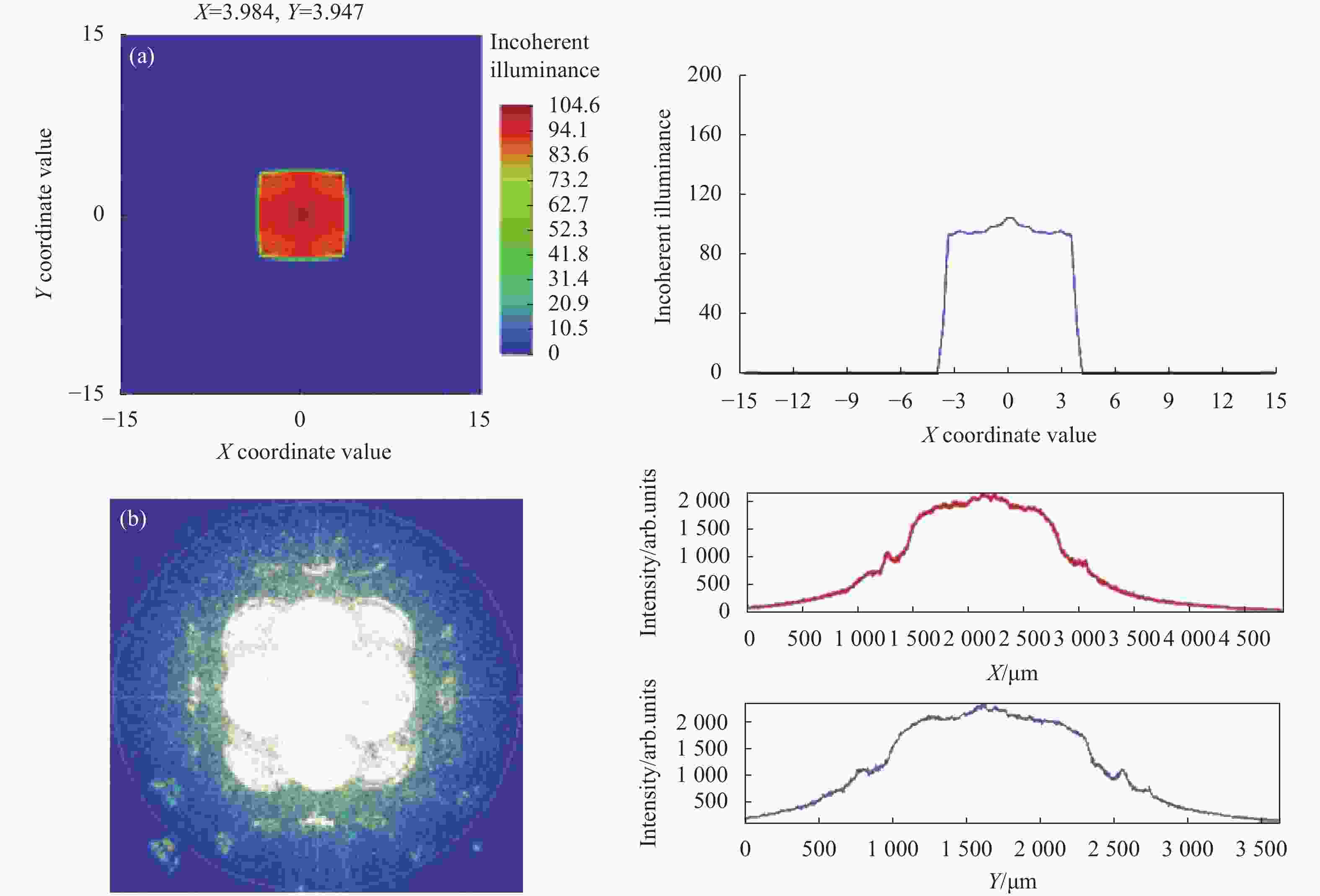
Figure 13. (a) Simulation result when
${f_{{\rm{L{A}}_1}}}$ is 6.3 mm; (b) Experimental result when${f_{{\rm{L{A}}_1}}}$ is 6.3 mm继续增加
${f_{{\rm{L{A}}_2}}}$ 至6.0 mm,${f_{{\rm{L{A}}_1}}}$ 分别为6.1、6.2 mm时,获取到第三组实验图如图14所示,匀化光斑增大。由公式(2)可知,由于a12固定不变且均大于${f_{{\rm{L{A}}_1}}}$ 与${f_{{\rm{L{A}}_2}}}$ ,当${f_{{\rm{L{A}}_2}}}$ 不变、${f_{{\rm{L{A}}_1}}}$ 增大时,DFT随之增大。当设定${f_{{\rm{L{A}}_2}}}$ 为6.0 mm、${f_{{\rm{L{A}}_1}}}$ 由6.1 mm增加至6.2 mm时,光斑尺寸由7.8 mm增加至8.4 mm,证实了实验的合理性。这种方式实现光束匀化相较于定焦透镜更加灵活,并且可以得到不同光斑大小的匀化光斑,为中低功率可见和近红外激光光束的匀化提供了一种新的思路。 -
文中利用OCA薄膜和超快激光打孔硅片实现了液体可调焦微透镜阵列的制作,采用调节去离子水注入体积控制薄膜形变的方法,实现了透镜焦距从1.46~10.44 mm的大范围调焦。分别通过聚焦光斑和成像实验证实了这种微透镜阵列在不同焦距下的均匀性。通过激光光束匀化整形仿真与实验证实仅通过改变单个微透镜阵列的焦距,而保持两个微透镜阵列的间距不变,可以实现矩形匀化光斑尺寸在7.2~8.4 mm内可调,但这种矩形匀化光斑尺寸的可调范围不大。可以预见,通过改变微透镜阵列中的单个透镜单元的排列可以得到不同形状的圆形光斑;增加单个透镜单元的数目可以进一步提升匀化光斑的均匀性。这种微透镜阵列有望在可见光和近红外中低功率下的可调匀化光斑应用领域中发挥作用。
Optical film liquid variable focus microlens array
doi: 10.3788/IRLA20210958
- Received Date: 2021-12-14
- Rev Recd Date: 2022-02-21
- Publish Date: 2022-08-05
Fund Project:
Science and Technology Research Program of Education Department of Hubei Province(Q20201006);Natural Science Foundation of Hubei Province(2020 CFB266)
-
Key words:
- microfluidic optics /
- liquid tunable-focus microlens array /
- simulation /
- homogenization
Abstract: Microlens arrays are widely used in beam homogenization, wavefront measurement, integrated imaging and other fields. A liquid tunable-focus plano-convex microlens array based on optical film (Optically Clear Adhesive, OCA) was demonstrated. A rectangular array of silicon microholes was used to control the aperture and arrangement of a single lens, and OCA optical film and deionized water were used as the shaping material of the microlens array. The focal length of the lens could be adjusted from 1.46 mm to 10.44 mm by adjusting the volume of liquid injection in the microfluidic cavity. According to the focusing and imaging experiments, it was confirmed that the microlens array had good uniformity. Finally, this microlens array was applied to laser beam homogenization and shaping. The beam homogenization and shaping were realized by a pair of microlens arrays. Furthermore, by fixing the spacing of a pair of microlens arrays, the size of the homogenized light spot can be adjusted within 7.2 mm to 8.4 mm, which provides a new idea for the adjustment of the size of the homogenized light spot.


 DownLoad: