


-
随技术提升,激光源会向着高光束质量的方向发展[1],而激光发射系统中气体及光学元件吸收能量产生的热效应不仅会降低发射光束的光束质量,还会影响系统的成像探测能力,已经逐渐成为工程研制中的关键问题[2-4]。
为降低热效应带来的影响,国内外提出了很多改善措施,其中报道比较多的还是在管道中注入低吸收系数气体的方法[5];采用这种方案时,通常会在末端形成隔离窗口,提高通道内低吸收气体含量,同时保护系统内光学元件不受污染[6]。针对共孔径发射探测系统,光学系统引入窗口后为避免窗口回射杂散光对发射及探测系统的影响,窗口在安装时通常与光束成一定倾角,导致一部分窗口回射杂散光会辐照在内通道的管壁上加热管壁,管壁的温升在激光光束对内通道气体的作用基础上进一步加热内部气体,改变气体温度、密度分布,引起光束波前畸变。
对于气体热效应问题,国内外学者开展了大量研究,参考文献[7]总结了大气热晕相关的理论模型及分析方法,参考文献[8]建立了一个光场流场耦合求解平台,研究了轴向流动中管道的稳态热晕效应,参考文献[9]分析了无气流激光内通道管壁温度对激光传输热效应的影响,参考文献[10]对比了不同形式的封闭管道热晕引起的波像差,参考文献[11]研究了瞬态热晕对发射光束质量的影响,参考文献[12]详细总结了气动光学效应的数值模拟方法,对于流场光场耦合的仿真计算具有指导意义;参考文献[13]研究了复杂通道内的流光耦合热效应特性;参考文献[14]利用光场流场耦合模型分析了通道轴向风速对传输光束波前相位的影响并评估了自适应校正的效果。这些工作均是考虑气体介质自身吸收激光能量的热效应,对于气体与固体之间的热交换并未考虑,而随激光技术的提升,固气耦合部分热效应的影响占比显著提升,已无法忽略不计,需对此展开详细的研究分析。
文中根据实际工程模型将光场以热源的形式加载到结构场,然后用有限体积法求解固气耦合计算域,得到直管道内气体的密度场分布后,根据Gladstone-Dale 关系式将管道内的密度场转化为折射率场,接着通过基于四阶龙格库塔(Runge-Kutta)求解光线微分方程的方法对通过直管道的光线追迹求解,分析了不同材料、壁厚、结构形式的管道在受到窗口回射杂散光辐照后升温引起的波前畸变。
-
光线在气体中传播时,气体折射率与密度遵循关系式[15]:
式中:ρ为气体密度;n 为气体的折射率;
$K(\lambda )$ 为气体的一种特性,也称Gladstone-Dale常数,由光的波长$\lambda $ 确定,在红外波段时:式中:
$\lambda $ 为入射光波长(μm);$K(\lambda )$ 单位为 m3/kg。根据此公式可将计算得到的密度场转化为折射率场,再根据折射率场计算出光束通过管道后的光程差
$\Delta {L_s}(x,y)$ (Optical Path Difference);波像差W(x,y)表征了实际波面与理想波面之间的差别,文中平面的波像差就等于光程差,即可求得笛卡尔坐标系下的波像差W(x,y):式中:s为光束传播距离;n(s1)为理想均匀折射率场;n(s2)为实际变折射率场;p、q分别是光线的起始点和终止点。
通过Zernike多项式来拟合一个与所求圆形孔径波像差最接近的理想波面,根据拟合的波面得到各像差信息和波面的PV、RMS值,并根据RMS值计算光束质量因子β值,进一步完成对光束质量的评估。
式中:r、θ为公式(3)中x、y在极坐标系所对应的值;an为第n项Zernike多项式系数;
${Z_n}(r,\theta )$ 为Zernike多项式的第n项;m为拟合的项数,文中取Zernike多项式的前37项进行拟合。 -
折射率任意分布介质中的光线传播方程如下:
式中:s为光线传播路径上的弧长;r为光线矢径;
$\nabla n $ 为折射率梯度。大多数情况下, 该方程基本没有解析解,一般采用数值方法进行求解,由于Runge-Kutta在达到相同精度的情况下的运算量较少,选用四阶Runge-Kutta法作为光线追迹的基本方法[16-17]。对于光线微分方程,令$T = n{\rm{d}}r/{\rm{d}}s = {\rm{d}}r/{\rm{d}}t$ 为光线矢量,其中引入参量${\rm{d}}t = {\rm{d}}s/n$ ,则方程可写为:已知光线追迹初始条件
$r = {r_0}(x,y,{\textit{z}}),T = {T_0}$ 时,可计算出函数D、光线矢径${r_n}$ 、矢量${T_n}$ ,然后带入数值求解方程可得到下一点的矢径${r_{n + 1}}$ 和矢量${T_{n + 1}}$ ,依次重复,即可完成整个光线追迹过程。 -
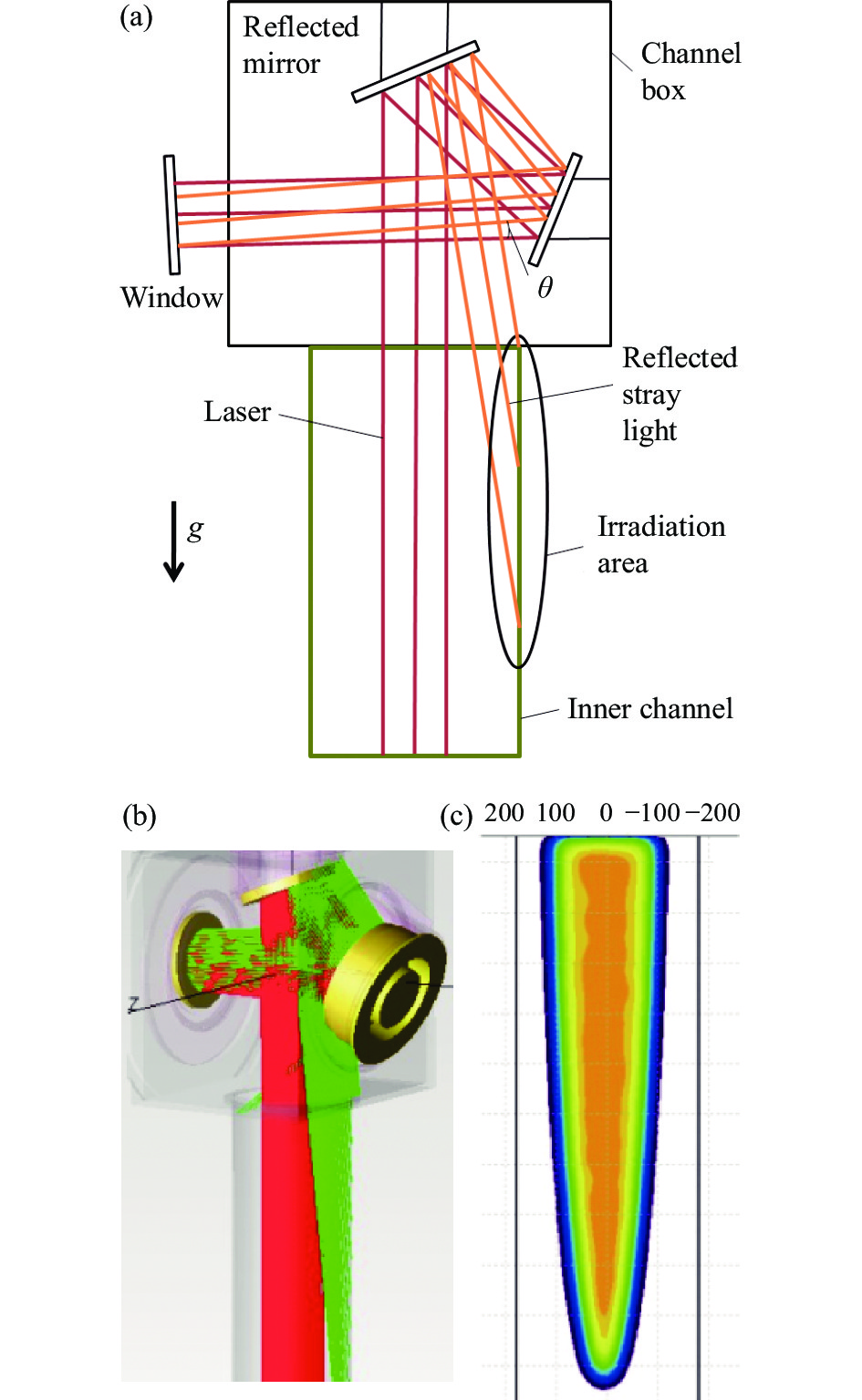
图1所示是受窗口回射杂散光辐照的内通道示意图,为避免窗口回射杂散光对共孔径探测的影响,安装时有一定的倾斜角,保证回射杂散光主要辐射区域在内通道的竖直圆管道部分;将辐照区域模型简化为一典型圆直管,图1(b)中绿色部分为回射杂散光,辐射在管道上后的辐照区域为(c)中区域。根据各部分结构的长度及激光光斑尺寸计算出管道壁面受辐照区域的坐标方程,然后将辐照能量以源项的形式附给管道壁面。整个结构处在重力场中,仿真计算时为真实地模拟自然对流情况也按照实际工况加入重力条件。

Figure 1. Irradiation diagram of window reflected stray light
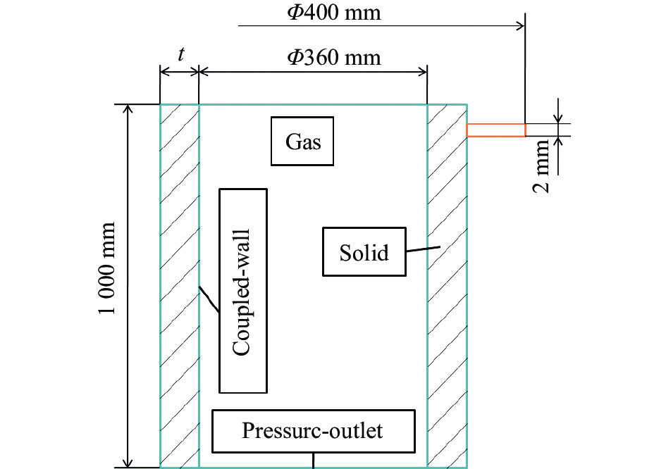
简化后的管道模型及尺寸如图2所示,流体通道部分长度1000 mm,直径Φ360 mm,外侧固体部分由管道的壁厚决定,为控制变量对比分析,文中选择了三种不同的固体材料:铝、铜、钢,计算工况有:壁厚8 mm的铝管/铜管/钢管,壁厚2~16 mm的铝管,壁厚2.4 mm的铜管,壁厚2.7 mm的钢管,壁厚8 mm的铝管外侧贴1 mm碳纤材料;同时考虑了在铝管外侧加散热翅片的结构形式,管道外侧加翅片的尺寸见图2橙色部分,翅片厚度2 mm、外径Φ400 mm,图中仅简化示意一个翅片,实际计算模型长度方向间隔50 mm布置一翅片。材料属性如表1所示。

Figure 2. Simplified model of round pipe
Material Density/
kg·m−3Cp/
J·kg−1·℃−1Heat conductivity/
W·m−1·℃−1Aluminium 2700 880 237 Copper 8900 390 383 Steel 8030 502 16 Carbon fiber 1500 800 800 Table 1. Material property
-
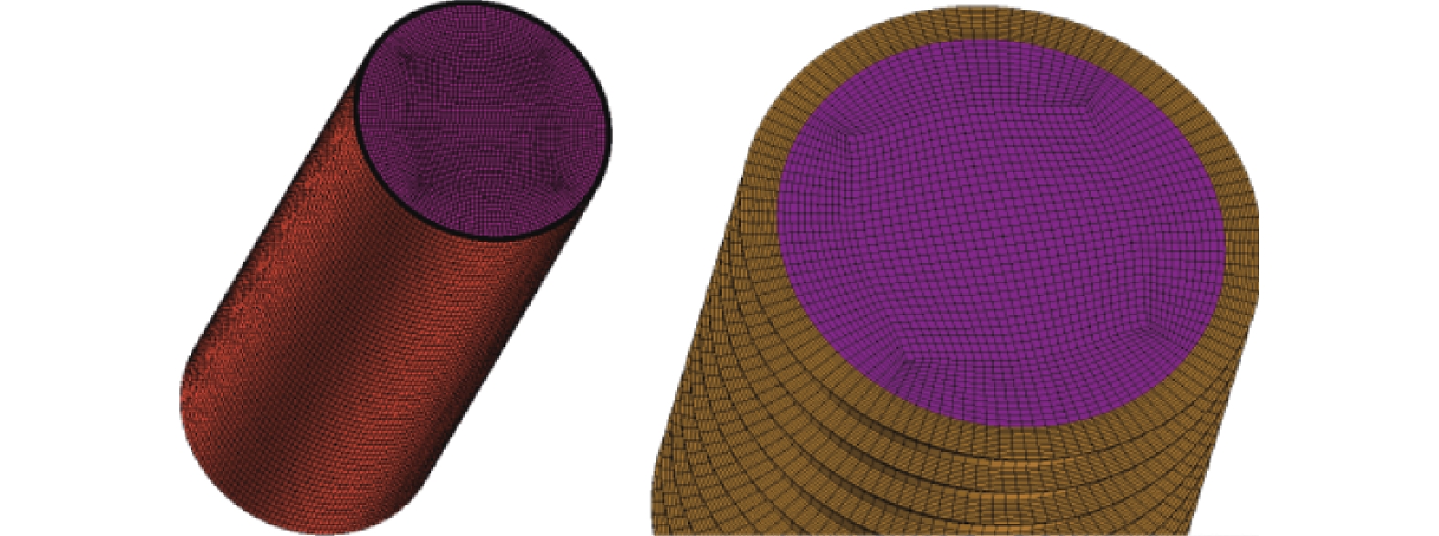
对上述物理模型进行仿真计算之前需对计算域进行离散化处理,固体和气体分别划分网格,最终的数值计算离散化模型如图3所示。

Figure 3. Numerical simulation of discretization model
仿真计算时管道各个边界条件见图2,整个通道内的气压变化忽略不计,上下边界均认为是压力出口边界,出口处压力与外界大气压相同;固体域与气体域的共同边界为耦合壁面,在耦合壁面上附加热源,热源作用在固体域上,固体域的温升通过热传导及自然对流引起附近气体的温升,热源的功率密度根据激光功率、窗口反射率、回射杂散光角度、管壁材料吸收率来进行计算,窗口反射率根据膜系评估其均值为0.05%,回射杂散光角度由窗口的倾斜角决定,实际工程结构中选用的倾斜角一般为0.5°~3°,光学通道内材料引入发黑工艺后,管壁吸收率普遍达80%以上,最终计算出来的热源功率密度约为2300 W/m2;为控制变量,直管固体域外壁面设置为绝热壁面,对于带散热翅片的管道外侧引入了强迫对流,在管道固体域外侧建立1 m×1 m×1 m的外部流域,外部流域的一侧边界设置为速度入口,模拟强迫对流的来流,其余边界设置为压力出口,固体域外侧设置为混合壁面,计算固体域热传导的同时也计算壁面与外侧气体的对流热交换。
文中借助Fluent软件模拟了上述模型工作一定时间后的情况,利用瞬态求解器,推进时间步长取0.05 s,初始温度设置为300 K;气体域采用基于压力的求解器求解三维雷诺平均N-S方程,利用标准k-ε湍流模型模拟管道内气体的自然对流,在整个计算域中加入重力,使用标准壁面函数模拟近壁区域的流动,管道壁面均为无滑移耦合壁面边界,管道上下截面设置为压力出口边界,管道内的气体可视为理想气体;固体域则根据不同工况选择相应的材料,利用有限体积法求解,固体温度场方程为:
式中:ρS是固体密度;CV是比热容;TS是固体温度;
${\lambda _{\rm S}}$ 是固体导热系数;$\overrightarrow n $ 是控制体外表面单位法向向量;固体与气体耦合壁面的热交换利用公式(12)计算:式中:q''是耦合壁面的热通量;h是对流换热系数;T*是空气的恢复温度;TSW是固体壁面温度。
-
文中基于以上理论基础及分析框架对上述物理模型展开了分析,研究了密封窗口回射杂散光对管道内壁温升及通过管道光束引起的波像差的影响,进行了管道设计参数影响程度的分析。
-
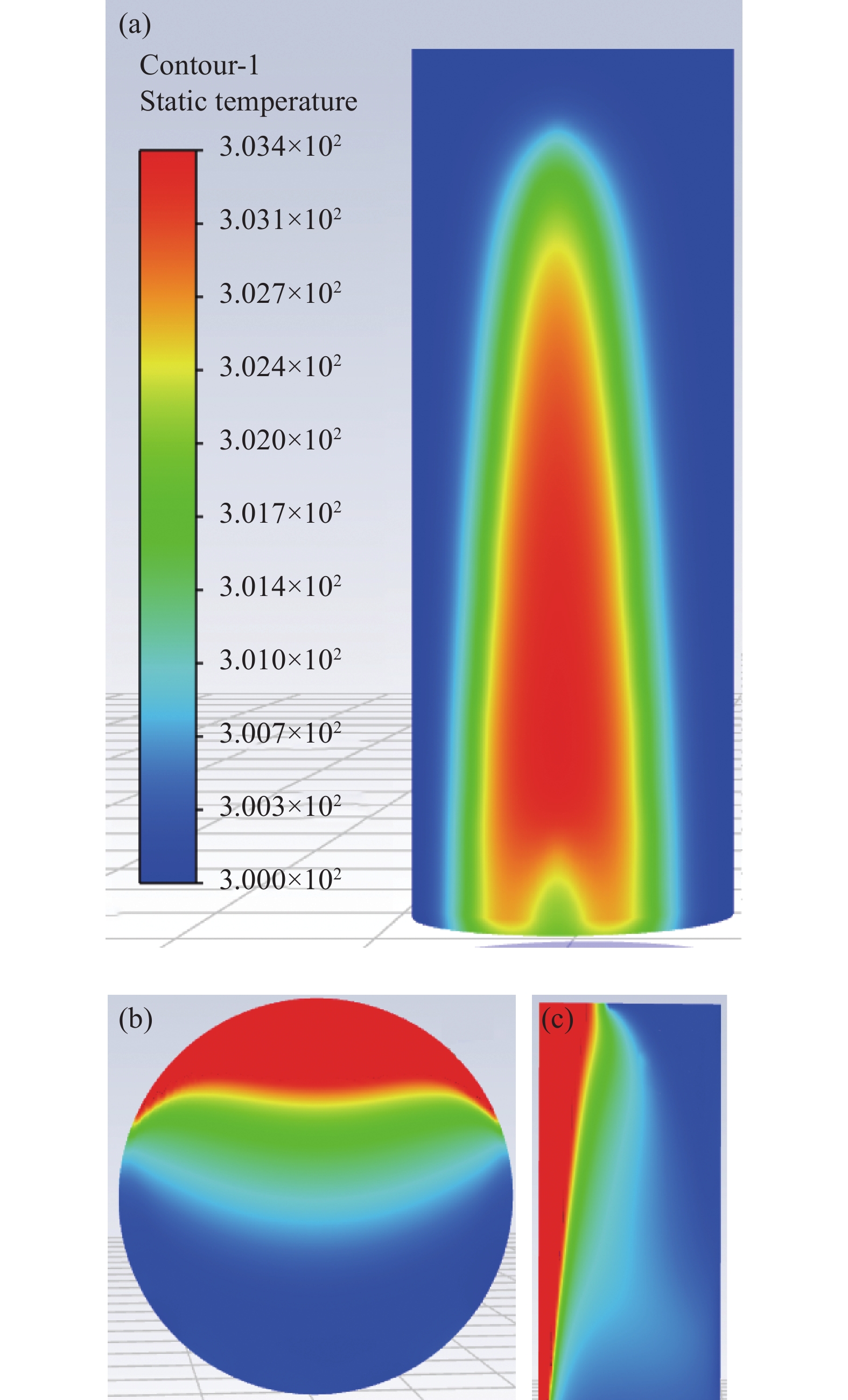
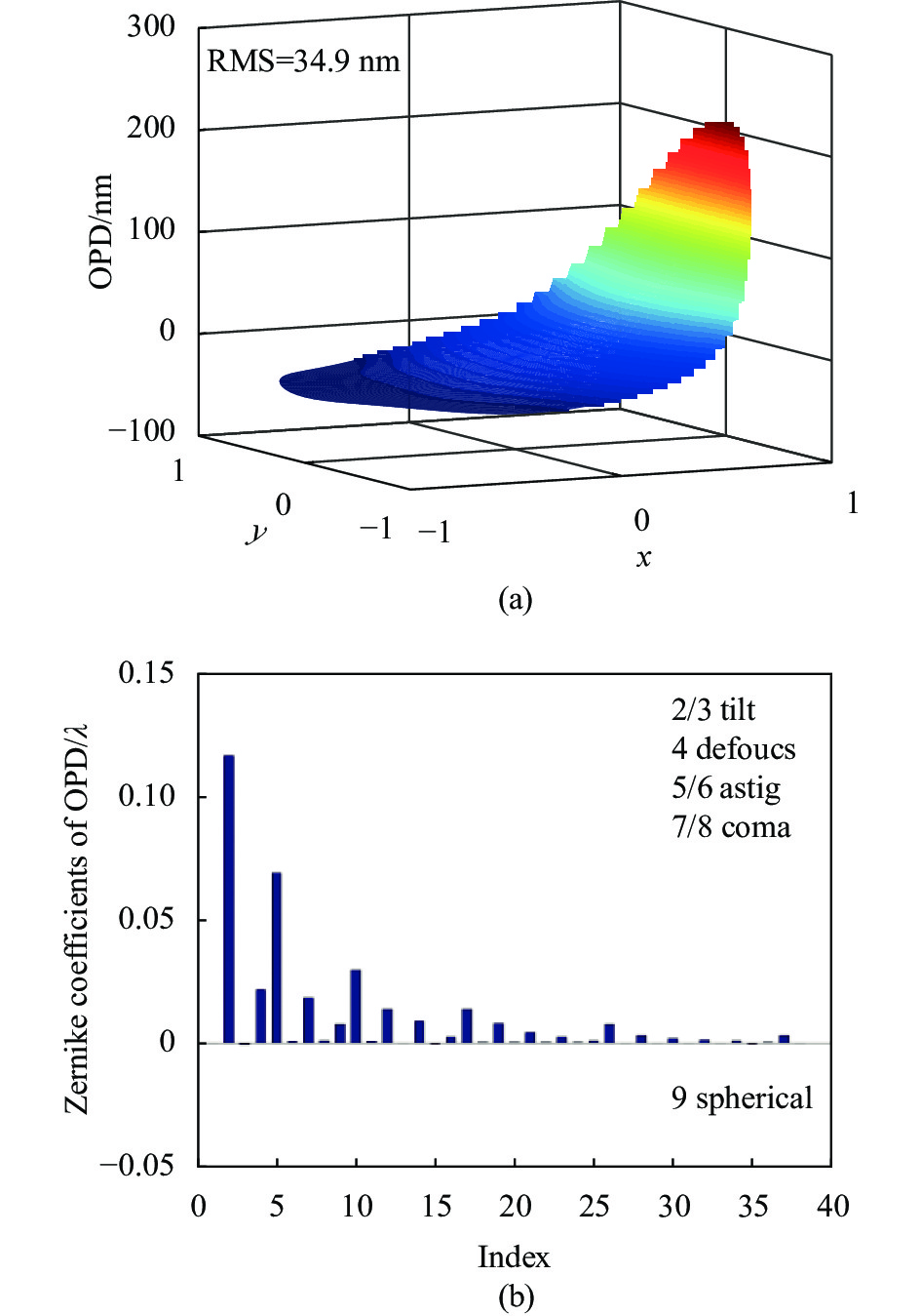
针对8 mm铝管展开了总辐照时间30 s的分析,窗口回射杂散光在管道的辐照区域类似图4(a)中的半椭圆形,图4(b)、(c)为管道截面气体温度分布,管壁受热升温部分加热管道内部气体,引起管道内部气体自然对流,升温气体分别从两侧和中部缓慢向中心区域扩散,在重力的作用下,下侧的升温气体形成,向上流动,对流换热使得管道上侧升温气体区域逐渐扩大,热边界层范围也逐渐增大,回射杂散光辐照引起了管壁最高3.4 K的温升,受热管壁一侧气体密度低于周围气体,导致管道内部折射率场变化,与管道同轴Φ300 mm的光束通过管道后的波像差分布见图5(a),波像差在高温侧突升,图5(b)中可以发现主要以一阶像差为主,其中第二项倾斜和第四项离焦、第五项像散占据了主要成分,第十项高阶像散也较为明显。
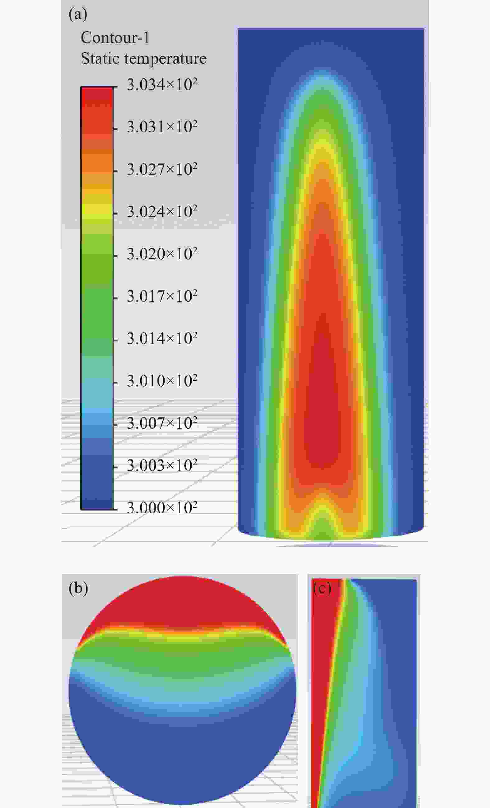
Figure 4. Temperature contour of pipe wall(a), and section(b), temperature cloud chart(c)

Figure 5. OPD (a) and Zernike coefficients (b) of pipe outlet
-
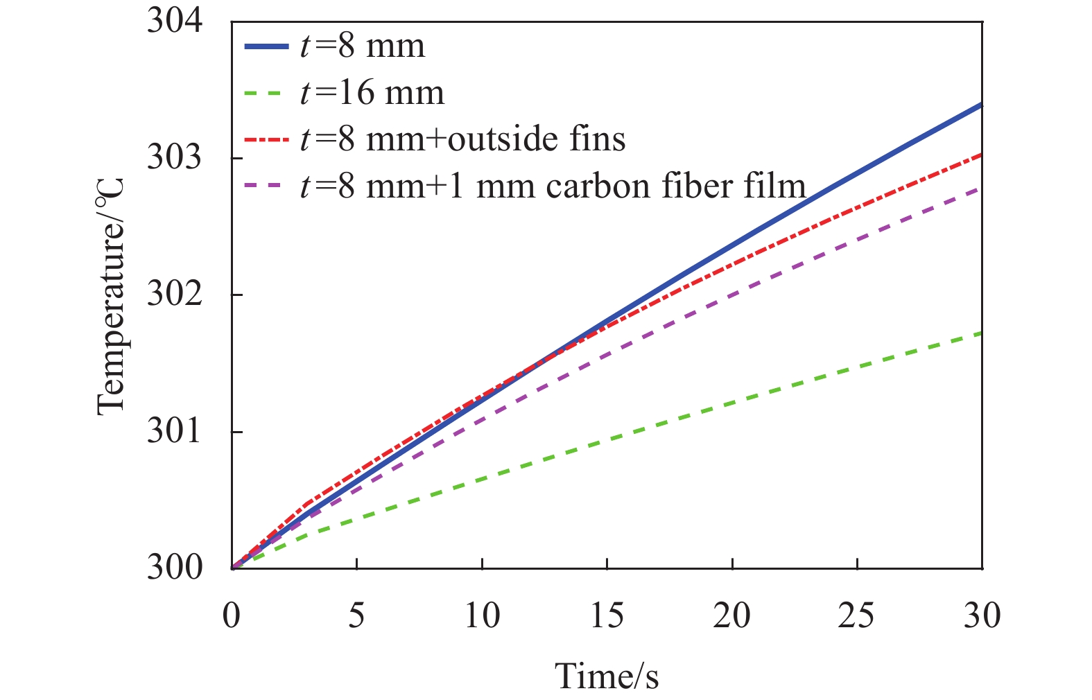
为有效地降低管道受回射杂散光辐照后的温升,提升探测成像质量,文中尝试了增加壁厚、增加散热翅片(强迫对流速度5 m/s)、增加高导热系数(800 W/(m·K))材料层的不同管道结构设计方案,从图6中可见,增加壁厚是降低温升最直接有效的方式,增加结构的热沉能够在短时间内有效降低管道的最高温,壁厚从8 mm增至16 mm,管壁最高温升由3.4 ℃降低为54%,仅有1.79 ℃;在管道外侧贴高导热碳纤维膜提升热导效率以及在管道外侧增加翅片,利用强迫对流散热的方式都能在一定程度上降低管道最高温升,但温升的降低不超过25%。对三种不同的结构设计进一步评估,如图7所示,蓝色条均为基础8 mm铝管温升值,第一组中绿色和黄色分别是对管道外翅片增加5、10 m/s的强迫对流的方案,流速增加,提升气体对流换热系数,可降低管壁最高温升,但对于时间短、温差小的结构来说,降温效果并不明显,10 m/s的强迫对流带来的温度降低仅14%;第二组中绿色和黄色分别对应管道外侧增加1 mm,导热系数为800、1600 W/(m·K)的碳纤维导热膜后的温升;第三组中绿色和黄色分别对应管道壁厚增加至10、12 mm时的温升,增加高导热系数的导热膜后,温升降低可达25%,增加壁厚则具有明显的降温优势,降温可达32.7%。

Figure 6. Temperature changing curve of different aluminum pipes
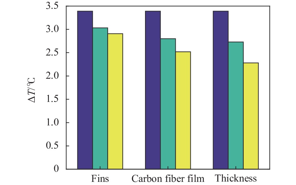
Figure 7. Comparison of influence of different structures on temperature rise of pipe wall
针对壁厚的影响单独开展了详细分析,图8所示是不同壁厚的铝管受窗口回射杂散光辐照后的温升变化,壁厚范围从2~16 mm,温升呈现与壁厚成反比的规律,厚度从2 mm增加至8 mm,温升降低了75%,厚度增加至10 mm以上后不再显著降低温升,工程应用中可对应选取5~10 mm壁厚的管道,避免过度增加结构质量和成本。
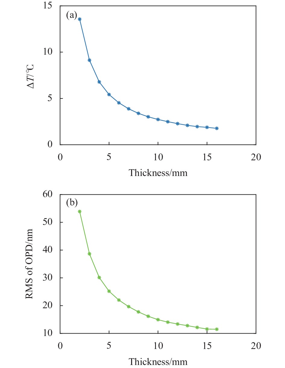
Figure 8. ΔT (a) and RMS of OPD (b) change curves with aluminum pipe thicknesses at t=30 s
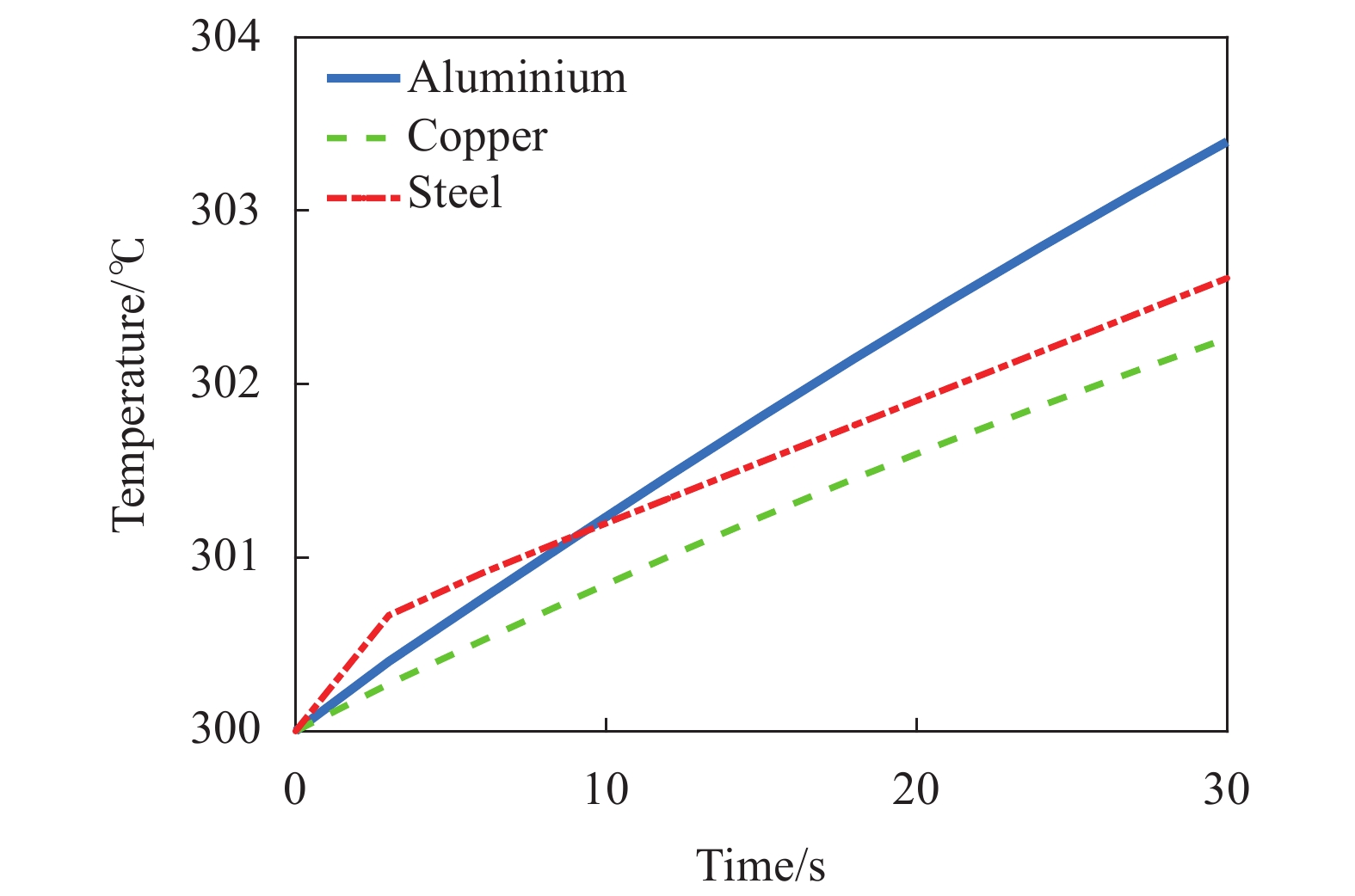
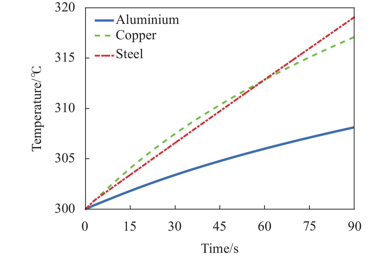
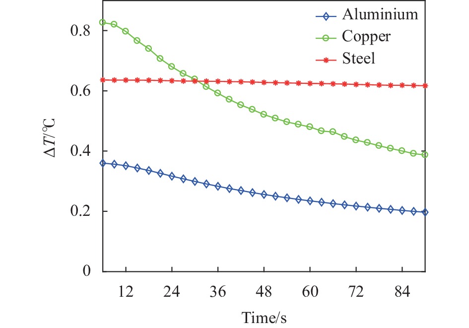
除管道的尺寸、结构形式外,管道材料的属性也直接影响管道的温升和波面畸变,文中分析了等壁厚和等质量两种情况对不同材料的影响。图9、图10分别是等壁厚、质量的三种材料在窗口回射杂散光辐照下的温度变化曲线图。从图9可看出:相同时间辐照下,三种等壁厚的材料,铜的温升最低,这对于有空间限制的热结构设计提供了参考:受尺寸限制的结构设计选材时,文中选用的三种材料里铜材料的选择可使得有外热源的情况下结构温升最低。图10展示了等质量的铝、铜、钢管道在相同辐照条件下的温升,针对等质量管道的分析共计算了90 s辐照效果来观察不同材料管道的温升规律。铝管道明显优于铜管和钢管,铜管虽导热快、导热效率高,但热沉小;钢管虽导热系数低,但热沉大,温升比铜管稍低;铝管综合了导热性能优良且热沉大的优势,30 s辐照时最高温升仅为等质量铜管的45%,90 s辐照时最高温升仅为等质量铜管的47%。图11记录了每3 s管道的温升增长值,可以看出:辐照初始的温升增长值主要取决于材料的比热容,随时间增加,热导率则决定了结构温升变化的梯度,铜管温升变化斜率最大,在辐照时间超过35 s后,已经比钢管的温升小,因此当结构需受长时间辐照时,应优先考虑选择导热系数高的材料。
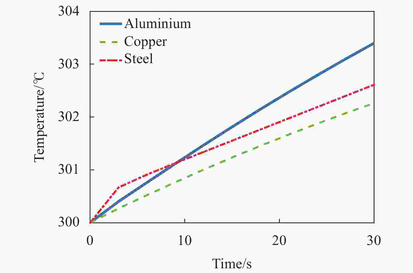
Figure 9. Temperature rise changing curves of three materials with equal thickness
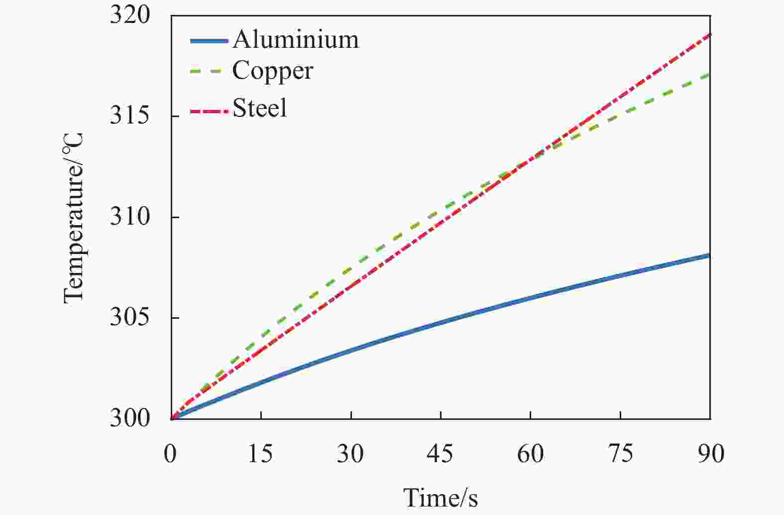
Figure 10. Temperature rise changing curves of three materials with equal mass

Figure 11. ΔT changing curves of three materials with equal mass
-
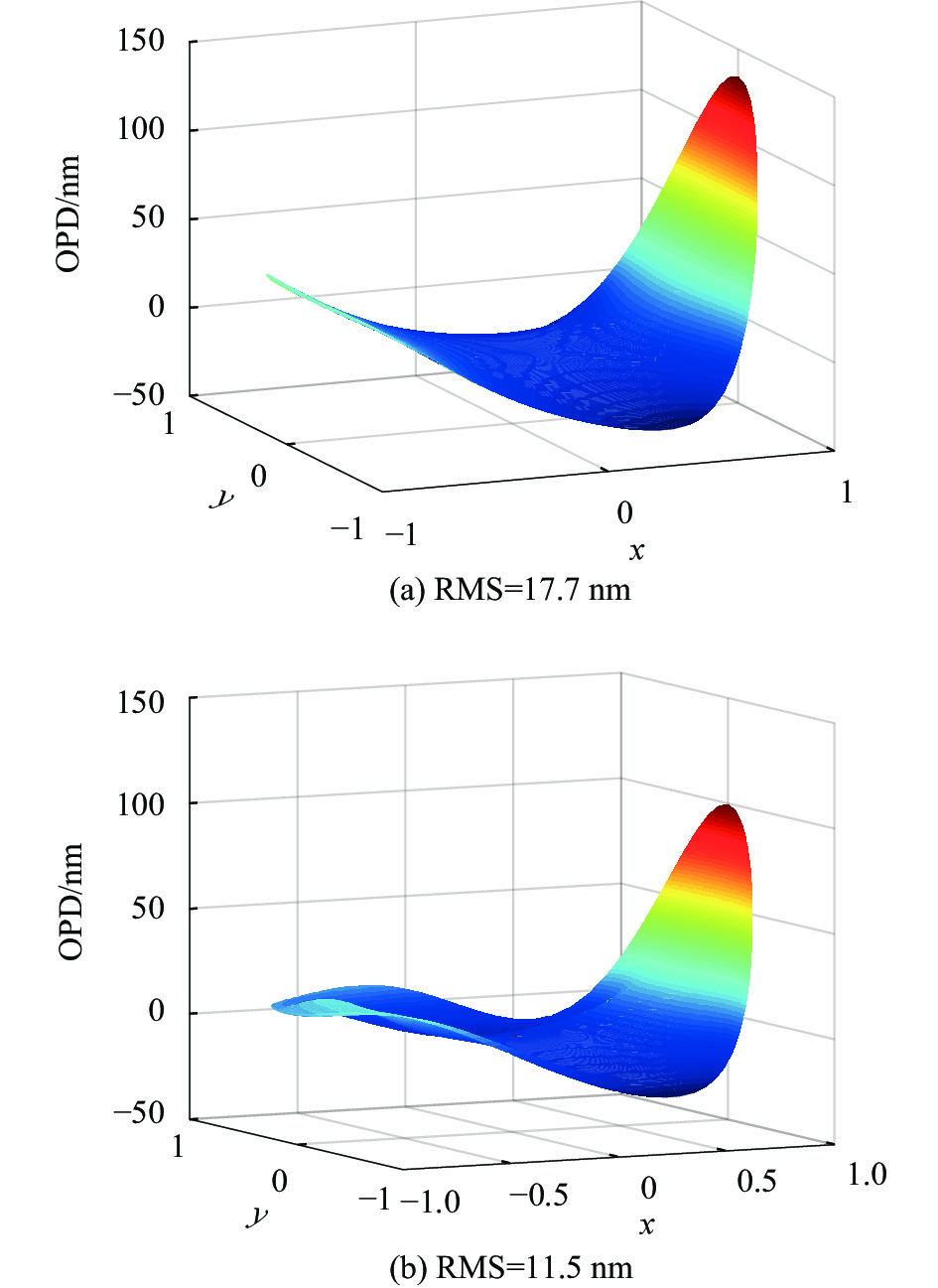
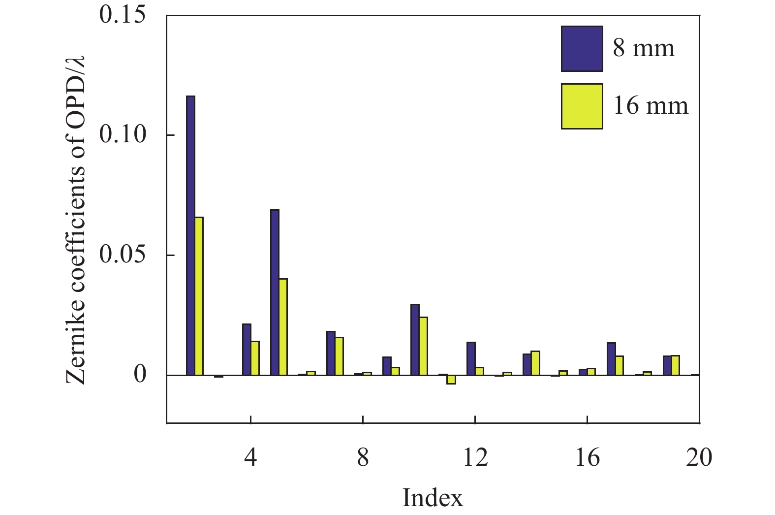
上文内容仅从管壁温升的角度分析了管道壁厚、管道结构形式、材料的影响,下文分析其对管道出口波像差的影响。根据上文固体域-气体域耦合求解的结果得到管道内部空气的密度场,将其转化为折射率场,再根据公式(10)进行光线追迹,得到管道出口的波前变化分布,并采用36阶泽尼克多项式对其进行分解,根据去平移和倾斜之后的波前RMS值来评价系统的波前变化。图12展示了8、16 mm壁厚的管道光线追迹后去平移和倾斜像差的波面,波前变化的整体分布基本一致,波像差主要受到辐照一侧管壁温升的影响。从图13中可以看出壁厚增加以后,主要的各阶像差均得到改善,倾斜和像散下降了约50%。

Figure 12. Ray tracing results of 8 mm (a) and 16 mm (b) thickness pipe

Figure 13. Zernike coefficient of OPD in the outlet of 8 mm/16 mm pipe
从表2数据可以看出管壁的温升直接影响通过管道的波前变化,波前RMS值的变化规律与管壁的温升规律一致:最高温升越小,引起波前变化的RMS值越小。增加受辐照段管道壁厚、提升管道热沉是降低光束波前畸变最有效的方案,在文中的算例中,16 mm的铝管受辐照引起的波像差变化最小,RMS值仅为21.4 nm,相比于2.7 mm的钢管的54.9 nm,降低了约60%,β值从1.16下降至1.02;通过管道增加散热翅片及外侧贴碳膜增加热传导的方式来降低壁温、改善波前畸变的效果并不理想;对于同等质量的管道,受辐照的铝管通道内的波前RMS变化仅为铜管和钢管的50%左右;基于以上分析可知,针对密封有窗口内通道的结构设计,选择合适的材料及在质量限制内适当增加壁厚是降低波像差最简单有效的方式。
Thickness/mm Material & structure Wave aberration in the 300 mm range β PV/nm RMS/nm Original Without piston and tilt Original Without piston and tilt 8 Aluminium 436.2 186.5 34.9 17.6 1.0665 16 Aluminium 339 123 21.4 11.5 1.0229 8 Aluminium+outside fins 410.2 213.9 30.1 21.2 1.0370 8 Aluminium+1 mm carbon film 410.6 152.8 33.1 15.1 1.0556 8 Copper 379.3 141.8 28.7 13.4 1.0415 8 Steel 404.8 188.4 30.2 16.5 1.0461 2.4 Copper 624.8 327.3 58.8 32.2 1.1863 2.7 Steel 638.0 399.3 54.9 35.2 1.1606 Table 2. PV & RMS of wave aberration in the pipe outlet
-
针对内通道窗口回射杂散光辐照加热直管引起的固气耦合热效应问题,文中建立固气耦合仿真分析框架,研究了窗口回射杂散光引起的管道壁面温度场及管道内气体密度场变化,并利用四阶Runge-Kutta数值方法求解了光线微分方程,完成管道Φ300 nm范围内的光线追迹,计算了光束通过不同管道之后的波前畸变。文中对比分析了不同管道材料、管道壁厚、管道结构形式的管壁受热温升及其对光束传输的影响,分析结果表明:管壁受热后的最高温升直接影响通过管道光束的波前变化,温升越高,波前畸变越严重;在影响管壁温升的几种因素中,增加管道壁厚、提升热沉是降低最高温升和波前RMS值最有效的方法,壁厚从8 mm增加至16 mm,最高温升降低54%,波像差降低40%,光束质量也有所提升;增加散热翅片以及高导热碳膜的方式来改善热效应的效果并不理想,采用高导热系数的导热膜,温升降低也不超过25%;同时,在结构设计中对于不同的条件限制,可针对性地选择材料以达到降低热效应的效果:若结构设计有质量要求,铝管在等质量条件下的温升最低;若结构设计受到尺寸限制,则同尺寸下高密度、高导热的铜管表现优异;对于需要长时间受到辐照的结构,应优先考虑导热系数高的材料。下一步的目标将针对其余的结构设计变量进行研究分析,如管道直径、管道截面形状等,设计出热效应最小的管道结构。文中的研究结果可为内通道结构设计及管道热效应抑制措施提供指导,同时文中的计算方法也可用于评估通道内其余源项引起的波像差。
Influence of solid-gas coupling thermal effect caused by stray light from laser window on beam quality
doi: 10.3788/IRLA20210966
- Received Date: 2021-12-15
- Rev Recd Date: 2022-01-21
- Publish Date: 2022-09-28
-
Key words:
- wave aberration /
- solid-gas coupling /
- sealing window /
- thermal effect /
- inner channel
Abstract: To achieve the sealing requirement, the laser transmission inner channel will add the window with an inclined angle at the end of thin channel, but the temperature rise caused by reflected stray light of the window irradiating the pipe wall will also increase the gas thermal effects. Aiming at the problem of irradiating and heating the straight pipe by the reflected stray light of the sealing window, a coupling simulation model of structure field-gas density field-optical field in the straight pipe was established, analyzing the influence of materials, wall thickness and structural forms on wave front distortion of beam. The analysis results indicate that among three materials of equal quality, aluminum, copper and steel, the beam wave front distortion caused by the aluminum pipe is the smallest, which is only 50% of that of steel and copper; reducing the wall temperature and the beam distortion by adding heat dissipation fins or high thermal conductivity carbon film outside the pipe is not ideal and the wave front RMS value is reduced by no more than 3%; increasing the wall thickness and raising the pipe heat sink are the most effective solutions to reduce the beam distortion, the RMS value of the aluminum pipe outlet reduces from 36.1 nm to 21.4 nm and each order aberration is improved while the wall thickness increasing from 8 mm to 16 mm. The research results can provide a certain reference for the pipe design of inner channel and thermal effects evaluation.


 DownLoad: