


-
X射线衍射晶体目前已经广泛应用于光谱与图像诊断领域,晶体种类也由早期的平面晶体发展到柱面、球面等多种类型的曲面晶体[1-5]。曲面晶体应用技术的发展为物理实验诊断提供了更为丰富的数据。超薄的柱面反射弯晶可以用于自由电子激光的高分辨光谱探测[6],最高谱分辨可达3×10⁴;球面弯晶单色成像技术兼具大视场、高光谱分辨和高空间分辨的优点[7-9],在ICF实验诊断中可以用于靶丸内爆流线观测[10]。在这些应用中,最主要的核心部件就是作为衍射元件的曲面晶体。曲面晶体的加工工艺有很多种[11],在这些工艺过程中,晶体的周期结构有可能受到不同程度的损伤,有时甚至会在局部区域内形成位错或断裂面,进而影响实验数据的质量。在一些大型激光装置上,发次资源是十分珍贵且有限的,曲面晶体必须事先进行必要的检测,合格后方可在大装置上使用,从而保证实验数据的有效获取。
对常规光学元件的表面检测通常采用可见光,但是对用于X射线衍射的曲面晶体,可见光只能检测曲面晶体的表面面型,无法对晶体实际衍射的晶面检测,其中有两个困难无法克服。首先,晶体的表面与实际起衍射作用的晶面之间往往存在一个小的夹角,因此在实际的成像光路中,可见光的成像情况与X射线存在一定的偏差[12];其次,晶体衍射是多个原子和电子的集体散射效应,X射线有一定的渗透深度,不同晶体的渗透深度在数微米到几十微米[13]。在晶体弯制时,工艺过程有可能会对晶体的内部微观结构造成一定影响,例如,局部的扭曲与变形,而可见光只能检测元件表面,不能反映晶体的内部缺陷。因此,必须使用X射线才可以准确地对弯制后的曲面晶体进行衍射晶面检测。
直接对整个曲面晶体表面做检测也会遇到一些实际困难。晶体的有效面长度通常约30~80 mm,宽度约为10~60 mm,直接对整个晶体检测光源要有足够大的立体角。此外,晶体对X射线的响应是以Bragg衍射定律为基础的,只有在匹配的Bragg角情况下才能观测到高强度衍射线发射。实验室的X射线光源通常为X射线管,只能提供一些常用靶材如Cu、Ti、Fe、Mo、W等的特征谱线,难以满足种类繁多的晶体匹配需求。如果光子能量低且光程比较大,空气对X射线的衰减也会造成数据获取的困难。
文中以柱面反射弯晶为例,提出了一种基于实验室条件的检测方法,其主要思想是将整个曲面划分为多个线段区间来分别检测,从而将面型缺陷转换为谱线的缺失、扭曲或移位。基于该理论模型,只要保证了晶体旋转的同轴性要求,就可以令特征光谱的衍射曲线保证足够好的重复性,这样不仅降低了光路排布的位置精度要求,对记录设备的尺寸要求也相应降低,可以有效地实现在实验室离线条件下对晶体弯制品质的检测,从而为弯曲晶体在大型激光装置上实验时可以有效获取高质量数据提供保证。该方法对于其他类型的弯晶检测也有一定的参考意义,只是在具体的表现形式上会有些许差别。
-
当柱面反射晶体弯制完成后,从表面看是均匀光滑且无裂纹缺角等明显缺陷的。但在将柱面反射弯晶真正用于物理实验前,还有两方面的参数需要检定。其一是柱面反射晶体的曲率半径是否如预期的要求。在光源、探测器以及柱面弯晶的转轴位置都固定的情况下,当柱面反射弯晶样品绕着转轴旋转时,如果晶体弯制得好,晶面就是均匀规则的,那么在记录面上特征谱线的衍射位置将是固定的,如果弯晶的曲率半径在弯制过程中有变化,特征谱线出射到记录面的位置也会发生相应改变。通过特征谱线的位移变化,就可以评估柱面反射晶体曲率半径与预设的标准值的偏差情况。其二是实际参与X射线衍射的晶面是否在弯制过程中受损。在实际使用中,有些晶体虽然可见光看来很正常,但在与X射线作用时谱线明显扭曲变形。如果谱线的形状出现局部的扭曲、变形,甚至分裂,那么就可以判断对应位置的晶体区域在弯制过程中受到损伤,则该弯晶样品不能用于大型激光装置实验,以避免对实验数据产生误判或误读。
柱面弯晶的检测原理如图1所示,实验时以X射线管作为光源,弯晶的转轴和记录面位置保持不变,柱面弯晶绕着转轴可以任意旋转。建立如图2的坐标系,其中X射线源位置为原点
$ O $ ,晶体的曲率圆心位置为S(xc, yc),晶体的曲率半径为$ R $ ,对应特征谱线波长的Bragg角为$ \theta $ ,特征谱线在晶体表面的衍射点位置为D(xd, yd),记录面到x轴的距离为$ L $ 。可以看到,当半径$ R $ 的值变化时,对应同样Bragg角$ \theta $ 的衍射点$D'$ 的位置处于S、O、D 3点决定的圆弧上。由此可以计算出$D'$ 的坐标,再根据对称关系算出衍射线的偏移量。理论上,D点的位置可以随意放置,但为了便于实验排布和计算,实际实验中选择了让$ \overline{SD} $ 平行于探测器表面的方向。
Figure 1. Schematic diagram of cylindrical curved crystal inspection
Figure 2. Illustration of cylindrical curved crystal optical layout
取
$ {y}_{c}=H $ ,则:此时,衍射线在记录面上的坐标为
${(x}_{0},L)$ ,则:要计算某一条已知波长的特征谱线,会对应同样的Bragg角
$ \theta $ ,那么由S、O、D 3点决定的圆的圆心坐标为${{S}}'\left({x}_{c}', {y}_{c}'\right)$ 如果
$ R $ 的值发生变化,即$R'=R-\Delta R$ ,那么角度$ \theta $ 对应的衍射点的位置为D'(x'd, y'd),从而在记录面上衍射线的位置也会改变。在图3中可以看到,衍射线的位置改变量与曲率半径和记录面到晶体的距离有密切联系。晶体曲率半径差别越大,相同Bragg角下的衍射位置与标准衍射位置偏差也越大,再经过晶体衍射后到达记录面的位置改变量也就越大,这个偏差是非线性的。记录面距离晶体越远,到达记录面的位置变化就越明显。在综合考虑了信号强度、空间限制等因素后,采用L为500 mm的排布方式来对柱面弯晶进行实验考核。

Figure 3. Relation diagram of radius of curvature vs position of diffraction line
-
最常用的弯晶材料是石英晶体:QTZ(1010)的2d值为0.8512 nm;QTZ(1011)的2d值为0.6687 nm。常用的石英晶体厚度有0.1 mm和0.2 mm两种,由于其弹性性能良好,适合用于制作不同曲率半径的弯晶。从实际的制作过程看,在曲率半径为100 mm时,更薄的石英晶体弯制成品率更高,厚的则容易发生断裂或破损等情况。
实验的光源采用Fe靶材X射线管,实验时设置的高压和电流分别为20 kV和30 mA,保证光源发射的特征谱线经过晶体衍射后仍然有足够的光强,可以被记录面有效探测。光路排布如图1所示,在X射线管的出光口位置加了约Φ2 mm的限光光阑,其目的是将X射线的立体角限制在一个较小的范围内,以避免杂散光对记录面的探测器产生干扰。X射线管的整体尺寸约为80 mm×80 mm×200 mm,它的光源位于其轴线上,实验时应用的是点源模式,光源大小约为1 mm×1 mm,光源到Φ2 mm限光光阑的距离为40 mm,其发散角为1.96×10⁻³ rad。
在弯晶检测实验中,为了保证足够的实验精度,有两方面需要特别注意。首先,柱面反射弯晶的旋转轴线必须与其曲率半径轴线重合,从而保证在弯晶旋转时晶体上各点是旋转对称的。为此特别定制了柱面反射弯晶的支撑旋转平台,采用一体式结构,并使用高精度数控车床制作,保证了晶体曲率半径轴线与旋转轴线精确重合。其次,对记录面最关键的要求是空间位置固定不动,从而保证旋转柱面弯晶检测不同位置的衍射线时有统一的位置标准。实际采用的记录系统是大面阵的CMOS探测系统,该系统主要由闪烁体光纤面板和CMOS大面阵探测器耦合组成。晶体衍射的X射线照射到闪烁体上,转换为波长550 nm的绿光,再经过光纤面板的限光和传导,图像被不失真地传递到CMOS芯片的感光面上,通过光电转化被记录为数字信号。CMOS大面阵探测器的有效面积为49.2 mm×24.6 mm,像元大小为48 μm/pixel,整套记录系统的线性度高于98%。
通过精确地排布光路,在实验平台获得了高分辨的铁材料特征谱线,如图4所示。Fe的
$K_\alpha$ 线强度约2 000,$K_\beta$ 的强度约为750。Fe的特征辐射$K_\alpha$ 的波长为0.1936 nm,$K_\beta$ 的波长为0.1757 nm,结合两条特征谱线的波长以及两者的间距,可以估算出$K_\alpha$ 线的半宽为0.00148 nm, Fe的$K_\alpha$ 特征谱线的谱分辨为130。这是因为光源的尺寸比较大,难以达到更高的光谱分辨。
Figure 4. Diffraction data image of cylindrical curved crystal in the lab
在实验中,为了获取多个晶面位置的数据采样,在弯晶处每隔5 mm设置一个数据采样点,整个晶体上一共选取了9个位置,这样可以保证实验数据反映的是整块柱面反射弯晶的弯制品质。多幅实验图像的位置比较显示,Fe的
$K_\alpha$ 线在CMOS大面阵探测器的位置仅移动了两个像素,即谱线位置移动了96 μm。从图3的谱线位置移动与弯晶半径变化的对应关系,可以得到柱面弯晶的半径偏差为40 μm,也即$ \Delta R/R $ 约为0.033%,这表明柱面弯晶的弯制精度达到了很高的水平。 -
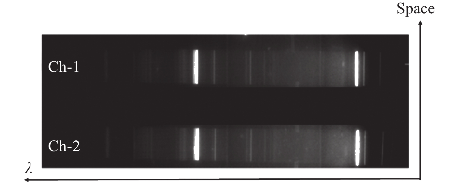
以柱面反射弯晶为核心部件的高分辨在线静态晶体谱仪已经在某大型激光装置上得到应用。采用4个束组激光驱动,靶型为高纯度2 mm×2 mm的Ti平面靶,激光能量共6.4 kJ,焦斑直径约Φ800 μm,激光功率密度约6.4×10¹⁵ W/cm2。利用该谱仪对Ti的类氢和类氦等多价态离子发射的X射线光谱进行在线测量。实验结果见图5,可以看到两个通道的柱面弯晶都工作正常,获得了高分辨的Ti离子光谱图像,且谱线在空间上均匀平直,表明柱面弯晶在二维宏观层面的整体结构保持一致。将Ti的类氦共振线的一级谱和二级谱作为定标基准,就可以将整段光谱的波长精确标识出来[14]。
Figure 5. Experimental data image of cylindrical curved crystal utilized in the large laser facility
-
文中提出了一种新型的基于X射线光源的柱面弯晶检测方法,该方法以X射线管作为光源,以位置固定的大面阵CMOS探测器作为记录设备,完成了柱面弯晶的实验室离线检测。经过建模计算和理论分析,选取了曲率半径120 mm的石英作为样品,光源到记录面距离为500 mm。离线检测实验选取Fe靶材X射线管作为光源,石英弯晶样品放在特别设计的旋转台上。实验时均匀选取了晶体上的9个位置进行采样,结果显示石英弯晶样品的反射光线在记录面上谱线位置移动了98 μm,对应到石英弯晶样品的半径偏差为40 μm,也即
$ \Delta R/R $ 约为0.033%,表明该检测方法达到很高的精度。经过检测的石英柱面弯晶在某大型激光实验装置上开展的激光打靶实验中也得到了应用,并获取了高质量的实验数据,证明了该方法的有效性。
High accuracy inspection of cylindrical curved crystal with X-ray source
doi: 10.3788/IRLA20211121
- Received Date: 2021-12-28
- Rev Recd Date: 2022-02-11
- Accepted Date: 2022-03-15
- Available Online: 2022-11-02
- Publish Date: 2022-10-28
Fund Project:
National Natural Science Foundation of China(12075219);Innovation Foundation of China Academy of Engineering Physics(CX20210019)
-
Key words:
- X-ray diffraction /
- cylindrical curved crystal /
- high accuracy /
- characteristic spectra /
- CMOS detector
Abstract: A novel method of cylindrical curved crystal inspection is presented utilized the X-ray tube as the light source and the CMOS detector coated scintillator fibre faceplate as the on-line recorder. According to the design of the high accuracy coaxial turntable, the whole cylindrical curved crystal surface is converted into several line segments to be detected separately, and the arrangement of optical paths and the position shift of spectral lines are calculated analytically. The iron target X-ray tube (the wavelength of Kβ feature spectral line is 0.193 6 nm) is selected as the experimental light source. The iron material X-ray tube is chosen as the X-ray source. The sample is quartz cylindrical curved crystal with the 120 mm radius of curvature. The feature spectral lines of Fe-Kα and Fe-Kβ are observed clearly. The Fe-Kα spectral line is shifted 96 μm through analyzing image of 9 sample locations on the cylindrical curved crystal. The deviation of the radius is 40 μm and ΔR/R is 0.033%. It shows that the sample was curved in high accuracy. The tested cylindrical curved crystal has been applied on the experiments carried on the large laser facility and the high performance spectral data is acquired. It demonstrates that the method of curved crystal inspection is available and useful.


 DownLoad: