


-
航空光电遥感器可用于全天时、近实时对地面信息进行观测,可获取清晰、可靠的图像信息,在军事侦察、反恐维稳、应急救灾、测绘制图等领域具有不可替代的作用[1]。然而航空光电遥感器在工作时所处的环境条件比较复杂恶劣。由于环境条件的变化,航空光电遥感器的焦平面产生不同程度的离焦,致使图像模糊,影响成像质量。为了保证航空光电遥感器在复杂恶劣的环境下的成像质量,必须校正光电载荷变化的像面,因此需要设计一套补偿焦平面离焦的调焦组件 [2-3]。
目前国内外常见的调焦机构方式有镜组移动式、焦平面反射镜移动式、像面移动式等。常规调焦机构配置形式大致分为三种:(1) 齿轮副串联蜗轮蜗杆副、偏心凸轮的传动方式,偏心凸轮的偏心量ε决定了调焦机构的最大调焦量±ε;(2) 齿轮副串联圆柱凸轮的传动方式,凸轮曲线槽沿光轴方向的投影距离是调焦机构的最大调焦量;(3) 齿轮副串联丝杠螺母副的传动方式,丝杠螺母副的有效轴向长度决定了调焦机构的调焦量。第一种结构配置形式多用于镜组移动式调焦,其缺点为线性调焦范围小、结构复杂、体积大;第二种结构配置形式仅适用于镜组移动式调焦,其缺点为凸轮曲线槽加工精度要求高,容易发生卡滞;第三种结构配置形式的缺点为丝杠螺母副会有传动空回误差,精度较低。
综合考虑调焦范围、调焦精度、整机包络等因素,并结合光学系统构型,设计了一套高精密紧凑型调焦机构,其具有精度高、结构紧凑、调焦范围大等优点。
-
在对调焦机构进行结构设计前要明确设计输入,主要包括调焦范围、调焦精度。正常情况下,光学系统允许光学载荷有少量的离焦量,当焦平面在允许的离焦阈值内时,成像质量基本不受影响,超过允许的阈值图像便模糊,成像质量严重下降[4-7]。允许的最大离焦量为光学载荷的半焦深,计算公式如下:
式中:
$ \left|\pm \delta \right| $ 为半焦深;$ F $ 为$ F $ 数;λ为光学载荷工作的中心波长。根据总体技术指标,结合光学系统设计可得因环境条件变化导致像面最大离焦量约为−3.5~+0.8 mm,在结构设计时,综合考虑调焦机构的复杂程度,允许机构占有空间尺寸,在保证调焦机构功能的前提下,尽量提高调焦范围,增加调焦裕度,确保成像质量,此调焦机构可实现的最大调焦范围为−4.5~+1.5 mm。此外,光学系统要求调焦机构的传动定位精度≤±10 μm,晃动精度≤±8"。
-
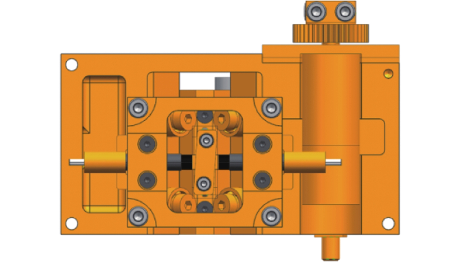
为满足上述调焦范围、调焦精度要求,结合光学系统构型,选用镜组调焦方式。在选择调焦镜组时,优先选择镜片/镜组轴向移动对光学元件倾斜、偏心等公差以及光焦度不敏感,但同时对调焦效果敏感的镜片/镜组作为调焦镜组。调焦机构包括三大部分:驱动-传动组件、相对移动组件以及位移传感器组件。调焦组件的结构简图如图1所示。

Figure 1. Structure diagram of the focusing mechanism
-
调焦机构的驱动-传动组件是决定调焦范围、保证传动定位精度的重要组件,由步进电机、精密减速器、齿轮副、轴承、蝶形弹簧、驱动轴、驱动螺母、消间隙螺母、销钉等构成,如图2所示。驱动轴末端加工成外螺纹与驱动螺母构成丝杠螺母副。

Figure 2. Structure diagram of drive-transmission component
根据调焦镜组的受力情况并结合实际结构尺寸,对调焦机构进行受力分析。在冲击、加速度等极限条件下,驱动调焦镜组需要电机力矩
${T}_{{\rm{end}}}$ 为200 mN·m。在丝杠螺母副传动效率$ \eta $ 、齿轮副传动比$ {i}_{1} $ 、精密减速器传动比$ {i}_{2} $ 的情况下,综合考虑航空相机的环境条件及安全可靠性,安全裕度选为$ n $ ,可根据公式(2)计算得到步进电机的力矩$ {T}_{DJ} $ :为提高调焦机构的传动定位精度,减小由驱动-传动组件间隙引入的传动误差、晃动误差,调焦机构采用了一种消间隙机构,消间隙机构由消间隙螺母、蝶形弹簧、驱动螺母以及定位销构成。消间隙螺母能够实现对蝶形弹簧和驱动螺母预紧作用,再通过销钉进行定位,从而达到消间隙的目的。
-
相对移动组件主要由固定支撑座、移动内框架以及导向机构三部分组成。其中导向机构由五个固定轴承和一个可运动轴承构成,五个固定轴承安装在固定支撑座上,运动轴承安装在旋转臂末端,通过弹性结构实现对运动轴承的预紧作用,这样便可适应由于温度变化导致的运动件的热胀冷缩而产生摩擦、应力以及接触不到的工况,实现对移动内框架的三点支撑,这种支撑方式能够使调焦镜组更好地适用于宽动态温度范围、大冲击、强振动等复杂的工作环境。
-
在紧凑型高精密测量系统中,精度通常和大位移测量相悖。在对大位移进行测量时,通常采用牺牲精度的方法来增大测量位移的量程,光栅式位移传感器、双频激光干涉仪等基于光反馈的位移传感器虽然具有高分辨率、测量范围大、抗电磁干扰能力强等优点,但也存在体积大、质量大、成本高等缺点。考虑总体体积包络、质量等因素,最终选用电涡流传感器。
调焦机构通过位置传感器对步进电机进行闭环控制,其中位置传感器由一对Kaman电涡流传感器和菱形被检测件构成。电涡流传感器的两个探头分别固定在固定支撑座上,菱形被检测件固定在移动内框架上,如图3所示。

Figure 3. Structure diagram of sensor component
由于调焦机构的调焦范围为−4.5~+1.5 mm,而电涡流传感器在线性段检测的范围很小,不满足对整个调焦范围的检测,为解决这一问题,将被检测件设计成菱形结构(夹角为θ),如图4所示,通过三角关系间接得到调焦机构的位置信息,如公式(3)所示。由于电涡流传感器采用差分信号原理,当调焦机构所处的外界温度发生变化时,菱形被检测件发生热胀冷缩现象也不会影响检测精度。当被检测件处于零位时,被检测件两侧的探头与被检测件之间的距离相等(即A=B)。

Figure 4. Schematic diagram of displacement measurement
式中:
$ X $ 为探头与菱形被测件在X方向的位移,通过标定差分信号获取;$ {L}_{Y} $ 为移动内框架实际位移。 -
误差分析是保证精密仪器性能与质量的一项重要环节,对于调焦机构来说,通过误差分析可以评估调焦精度的是否满足光电载荷的成像质量要求。调焦机构的误差主要源于传动误差和传感器组件误差,其中传感器组件误差主要包括电涡流传感器的线性度误差和电涡流传感器组件间接测量误差[8-13]。
-
由于光学系统要求调焦机构具有很高的灵敏度,故通过精密减速器大传动比将步进电机的步长细化,并且采用消间隙结构提高提高丝杠螺母副的传动定位精度。另外,调焦机构采用闭环控制方式,以调焦镜组的实时位置作为反馈信息,因此整个传动链路对调焦机构的精度几乎没有影响。但整个传动机构在装配过程中存在装配误差,装配误差的大小与检测设备精度有关,因此综合分析调焦机构的传动误差为
${\Delta }_{1}=\pm 2.5\;{μ}\mathrm{m}$ 。 -
调焦机构选用电涡流传感器,菱形被检测件作为线性位移测量传感器,根据产品手册,电涡流传感器的线性误差为满量程
$ {l}_{\mathrm{m}\mathrm{a}\mathrm{x}}=0.5\;\mathrm{m}\mathrm{m} $ 的±0.5${\text{%}} $ ,因此,电涡流传感器的的线性度误差为:由于调焦机构采用间接测量方法增大传感器线性位移测量范围,两个电涡流传感器安装在菱形被检测件两侧,通过标定差分信号原理得到电涡流传感器在图4中X方向的位移,标定设备的精度决定间接测量方法的误差大小,因此,采用这种标定间接测量方法的误差为
${\Delta }_{\mathrm{s}2}=\pm 3\;\text{μ}\mathrm{m}$ 。因此,调焦机构的传感器组件误差为
${\Delta }_{2}= \pm \sqrt{{{\Delta }_{\mathrm{s}1}}^{2}+{{\Delta }_{\mathrm{s}2}}^{2}}=\pm 3.9\;\text{μ}\mathrm{m}$ 。 -
由误差合成理论可知,调焦机构的误差
$ \Delta $ 可由调焦机构的传动误差和传感器组件误差合成得到:满足光学系统提出的不大于10 μm的精度要求。
-
由于航空光电遥感器选用镜组平移的调焦方案,影响成像质量的因素除了传动误差,还有调焦镜组的晃动误差,因此,必须对调焦机构进行传动定位精度实验和晃动精度实验[14-15]。
在实验过程中,将双面平面反射镜胶粘在调焦机构的移动内框架上,并将调焦机构放置在光学平台上,采用双频激光干涉仪作为传动定位精度检测设备,通过调整附件对其进行高精度位移测量;同时采用自准直仪作为晃动精度检测设备,通过调整自准直仪找到反射镜所成的像对其进行高精度角度测量,实验场景如图5所示。

Figure 5. Diagram of experimental scene
在传动定位精度实验过程中,通过控制步进电机正转使移动内框架前向移动,同时,在整个调焦行程内双频激光干涉仪每间隔0.02 mm采集并记录一次移动内框架的相对位置信息;驱动步进电机反转,重复上述实验过程。定位精度实验过程中,步进电机正转、反转均采集301个实验数据,将采集到的实验数据进行分析,得到曲线如图6所示。

Figure 6. (a) Relative displacement curves and (b) residual error curves of focusing mechanism
由图6可知,步进电机在正转、反转两种工作模式下,移动内框架位置信息拟合曲线为直线,残差在±6 μm以内满足光学系统提出的不大于±10 μm的精度要求。
在晃动精度实验过程中,通过控制步进电机正转使移动内框架前向移动,同时,在整个调焦行程内自准直仪每间隔0.02 mm采集并记录一次移动内框架在水平和竖直两个方向上的晃动误差;驱动步进电机反转,重复上述实验过程。晃动精度实验过程中,步进电机正转、反转均采集301个实验数据,将采集到的实验数据进行分析,得到曲线如图7所示。

Figure 7. Sway precision curves of focusing mechanism while stepping motor rotates (a) clockwise and (b) anticlockwise
由图7可知,步进电机在正转、反转两种工作模式下,移动内框架在水平、竖直两个方向上的晃动误差均在±4″以内,满足光学系统提出的不大于±8″的精度要求。
-
为满足航空光电遥感器轻小型、高质量成像等要求,调焦机构选用消间隙丝杠螺母副传动方式,实现了调焦镜组高精度直线往返运动,解决了由工作环境变化引起的焦平面离焦的问题。通过对调焦机构进行传动定位/晃动精度实验可知,该调焦机构在调焦范围内传动定位精度在±6 μm以内,晃动精度在±4″以内。经过飞行试验,航空光电遥感器调焦机构工作稳定可靠,并获取了高质量的图像。实验结果证明,该调焦机构具有结构紧凑、可靠性高、调焦精度高等优点,为航空遥感器朝着轻小型、高精度成像方向奠定基础。
Design of high precision and compact focusing mechanism for aerial photoelectric remote sensor
doi: 10.3788/IRLA20211122
- Received Date: 2021-12-29
- Rev Recd Date: 2022-03-29
- Available Online: 2022-11-02
- Publish Date: 2022-10-28
Fund Project:
Shaanxi Province Technology Innovation Guidance Special Fund(2017 CGZH-RGXQ-04)
-
Key words:
- aerial photoelectric remote sensor /
- focusing mechanism /
- anti-backlash screw nut pair /
- eddy current sensor
Abstract: Aiming at the defocusing problem of aerial photoelectric remote sensors in different working environments, a moving lens group is used to adjust the focus to ensure its imaging quality. The focusing mechanism adopts the anti-backlash screw nut pair as the transmission mechanism, adopts 6 precision bearings and elastic preload components as guide mechanism and adopts a pair of eddy current sensors and a diamond-shaped detected part as the displacement sensor to ensure the focusing accuracy to the greatest extent under the limited envelope size. The precision analysis of the focusing mechanism was carried out. And a test platform was built to carry out the transmission positioning accuracy experiment and the shaking accuracy experiment. The experimental results show that the transmission positioning accuracy of the focusing mechanism is within ±6 μm, and the shaking accuracy is within ±4″, which meets the design requirements of focusing accuracy proposed by the optical system.


 DownLoad: