


-
相位敏感光时域反射系统(Phase-Sensitive Optical Time-Domain Reflectometer, ϕ-OTDR)基于瑞利后向相干散射和外差检测原理[1],可对光纤沿线振动/声音进行分布式定位与实时在线监测,对扰动事件进行定性和定量分析,具备分布式光纤传感技术的独特优势,在重要场所非法入侵监测、非法施工破坏监测、长距离油气管线安全监测、交通轨道安全监测等领域得到了广泛应用,解决方案也日趋成熟[2];同时,其在分布式光纤水听、油气勘探及压裂微地震检测、自然灾害预警、核武器爆炸试验监测等低频领域体现了极高的应用前景,是目前的研究热点[3-4]。
近年来,海上航运和海底开采活动日益频繁,导致海洋背景噪声越来越严重,且随着水下目标降噪水平的提升,其辐射噪声水平已低于海洋背景噪声,这给水下目标探测带来了很大的困难,当潜艇在低速运行或静止时,只发出微弱的低频次声信号,水下目标产生的声源信号主要集中在100 Hz以下的甚低频中,且相比高频段信号,甚低频信号更难得到抑制,更容易被发现[5]。油气开采人员通常会在地面有序地进行定点爆破或在井中进行压裂操作,利用人工激发的微地震信号,勘察油气储量或开采甜点,提高油气采收效率,产生的信号频率一般小于100 Hz,其中,甚低频段的数据资料对于油气生产更具指导意义,而地震、海啸、火山喷发、核武试验等引发地质结构振动的频率一般低于10 Hz[6-7]。在电力行业中,输电线缆的舞动频率一般低于3 Hz,是一种在风的激励下架空电缆线所产生的低频、大幅度的自激振荡,多发生在覆冰的电缆线上,容易导致电缆的断裂[8]。低频信号在介质中传输损耗小,穿透能力强,传播距离远,而上述热门研究领域的有用信号主要集中在低频段,如果结合ϕ-OTDR系统的自身优势,进一步实现低频振动/声波的探测,就能更好地实现对灾害、威胁事件的提前预警或提高能源开采效率。
ϕ-OTDR系统对外界振动/声波信号具有特定的频率响应范围,此范围包含了系统可以响应的外界扰动的最小频率和最大频率。频率响应范围与系统光路结构密切相关,国内外学者通过对光路结构的改进已经把最大响应频率扩展到MHz级别,但是对低频振动信号的探测依旧是一个难点,多为几十Hz[8-9]。2012年,Qin等在外差探测的基础上提出了一种小波变换技术,该项技术可以抑制传感光纤中不同位置偏振态变化引起的随机噪声,系统最低探测频率为20 Hz[10];2017年,Zhang等提出了一种将传统外差探测结构与具有查表方案的非平衡3×3耦合器相结合的传感系统结构,提高系统信噪比,该系统的最低探测频率为50 Hz[11];2019年,南京大学傅思怡等人在传统ϕ-OTDR外差相干结构中引入了延时光路与非延时光路的自相干结构,获得了窄线宽激光光源频漂造成的相位变化,通过差分算法获得了0.5 Hz的低频振动的信号,减少了光源频漂对低频振动定量测量的影响;此外,对自相干部分进行额外的隔振处理,隔离了外界环境的振动,温变等低频噪声的作用,减少了背景噪声对低频振动定量测量的影响[9]。
但是在以往的系统结构中,仅考虑了脉冲触发信号与脉冲斩波信号的时钟同步控制,忽视了系统中声光频率调制部分由于脉冲斩波信号与频率调制信号时钟源来自不同时钟,由时钟稳定度差异引入的相位异步的现象,每个脉冲重复周期中的探测光存在随机低频相位噪声。为此,文中基于典型外差相干探测的ϕ-OTDR数值模型,分析因时钟不同源引入的相位异步问题及其对系统性能的影响,设计脉冲触发信号、脉冲斩波信号与频率调制信号同步驱动与控制装置,提高系统自身的相位稳定性,降低低频噪声干扰,采用数字I/Q解调方法对采集数据进行处理,并在同一实验条件下,与目前广泛采用的脉冲触发信号和脉冲斩波信号同源而与频率调制信号非同源的ϕ-OTDR进行对比,验证其对ϕ-OTDR系统的低频响应性能改善效果,提高系统在低频监测领域的适用性。
-
现有的ϕ-OTDR系统,使用声光调制器对光波进行调频,使探测光波的频率
${f_{{c}}}$ 变换为$f = {f_{{c}}} + {f_{{\text{AOM}}}}$ 的光波,同时利用脉冲斩波信号将连续光变为脉冲光。对于大多数声光调制器,频率调制信号的时钟来自驱动器内部,脉冲斩波信号由采集卡TTL触发输入,两种信号的时钟存在非同源问题。而在现有的理论推导过程中,并未考虑声光调制器频率调制信号时钟和脉冲斩波信号时钟的非同源问题。声光调制器内部的频率调制时钟信号
$ {x_m}(t) $ 可以表示为:式中:
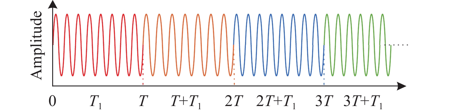
$ {A_m} $ 为频率调制时钟信号的幅值;$ {f_{{\text{AOM}}}} $ 为其调制频率;$ {\varphi _0} $ 为其初始相位;$ t $ 表示时间;$ {x_m}(t) $ 的波形示意如图1所示。
Figure 1. Schematic diagram of frequency modulated clock signal waveform inside acousto-optic modulator driver
输入声光调制器的脉冲斩波信号
$ {x_p}(t) $ 可以表示为:式中:
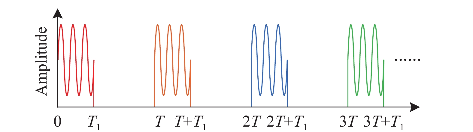
$ rect( \cdot ) $ 为矩形函数;$ {A_p} $ 为脉冲斩波信号的高电平幅值;$ T $ 为脉冲斩波信号的周期,相应的脉冲斩波信号重复频率为$ {f_{{\text{PULSE}}}} = {1 \mathord{\left/ {\vphantom {1 T}} \right. } T} $ ;$ {T_1} $ 为脉冲斩波信号高电平的持续时间;$ k = 0,1,2,3 \ldots $ 等整数;$ {x_p}(t) $ 的波形示意图如图2所示。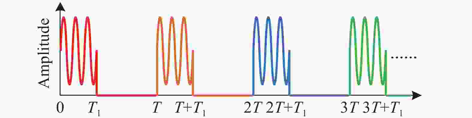
Figure 2. Schematic diagram of pulse chopper signal waveform input to acousto-optic modulator driver
$ {f_{{\text{AOM}}}} $ 为几十MHz量级,常用的规格包括40、80、200 MHz等;$ {f_{{\text{PULSE}}}} $ 取值范围一般为几kHz到几十kHz,检测长度为10 km的传感光纤时,$ {f_{{\text{PULSE}}}} $ 可设定为10 kHz。为了保证脉冲斩波信号和频率调制时钟信号的相位同步,$ {f_{{\text{PULSE}}}} $ 需要为$ {f_{{\text{AOM}}}} $ 的整数倍分频,即$ {f_{{\text{PULSE}}}} = {{{f_{{\text{AOM}}}}} \mathord{\left/ {\vphantom {{{f_{{\text{AOM}}}}} N}} \right. } N} $ ,$ N $ 为正整数。理想情况下,声光调制器驱动器输出的脉冲调制信号波形如图3所示,即每个脉冲周期内的调制波形起始相位、波形和频率相同。
Figure 3. Schematic diagram of pulse modulated signal waveform output by acoustooptic modulator driver
但是,现有系统中脉冲斩波信号源与频率调制信号时钟源来自不同时钟,即使
$ {f_{{\text{PULSE}}}} $ 完全等于${f_{{\text{PULSE}}}} = {{{f_{{\text{AOM}}}}} \mathord{\left/ {\vphantom {{{f_{{\text{AOM}}}}} N}} \right. } N}$ ,同样会导致声光调制器输出的频率调制脉冲光信号在每个脉冲周期中的脉冲光初始相位存在随机抖动,存在相位异步现象,如图4所示,斩波信号脉冲宽度90 ns,${f_{{\text{PULSE}}}} = 10 \;{\rm{kHz}}$ ,$ {f_{{\text{AOM}}}} = 80 \;{\rm{MHz}} $ ,即$N = 8\;000$ ,以脉冲斩波信号为参考,由示波器以10 s为间隔采集的经等比例衰减的声光调制器驱动器输出的脉冲调制信号。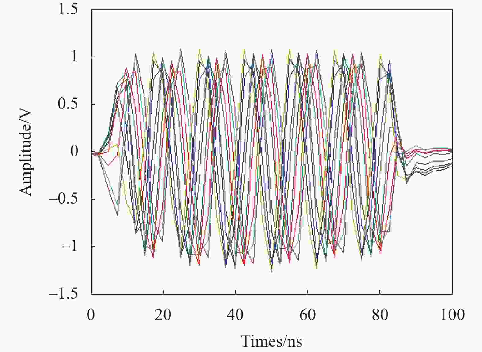
Figure 4. Pulse-modulated signal curves output from a conventional acousto-optic modulated driver
图4中,各曲线分别代表不同脉冲周期中,脉冲调制信号频率完全一样,均是
$ {f_{{\text{AOM}}}} $ ,但是由于输入的脉冲斩波信号与声光调制器驱动内部频率调制信号不是同一时钟,使得输出的脉冲调制信号在不同脉冲周期的起始相位不同,且具有随机性,导致波形在时域上存在沿时间轴的轻微抖动。由参考文献[12]可知,两个时钟非同源信号的角频率的误差模型可以表示为:
式中:
$ \Delta {\omega _n} $ 表示两个时钟角频率准确值的差值;$ \Delta {k_n} $ 表示两个时钟稳定度的差值。当存在时钟非同源问题时,ϕ-OTDR系统所检测的后向瑞利散射光[13]应重新表示为:
式中:
${\omega _c} = 2\pi {f_{{c}}}$ ,${\omega _{\rm{{AOM}}}} = 2\pi {f_{\rm{{AOM}}}}$ ,其他参数定义可参照参考文献[13],当光纤存在扰动时,引入相位变化量$ \varphi (t) $ 时,平衡探测器的输出功率为:经模数转换,数据采集卡采集到的数字信号为:
公式(6)中,如果频率调制信号时钟和脉冲斩波信号时钟不同源,仅存在准确值的差值
$ \Delta {\omega _n}n $ ,该差值仅引起后向瑞利相干散射光的相位固定偏移量$ \Delta {\omega _n} $ ,不会对扰动信号的测量结果产生影响。$ \Delta {k_n}n $ 为两个时钟不同源,稳定度差异引起的相位变化量,时钟稳定度$ \Delta {k_n} $ 并非恒定不变的常数,是一个统计数值,相比于$ \Delta {\omega _n}n $ 是一个缓变信号,因此,导致的后向瑞利相干散射信号的变化也是缓慢的、低频的。当测量高频扰动时,可以通过高通滤波器滤除其带来的低频噪声,从而实现对高频扰动的定量检测;但当测量低频扰动时,由于扰动事件也位于低频区间,无法通过滤波器去除其带来的低频噪声,从而导致低频扰动事件无法被区分,对扰动信号引起的相位变化$ \varphi (n) $ 造成干扰,影响扰动信号的相位解调结果准确性和ϕ-OTDR系统低频响应性能。 -
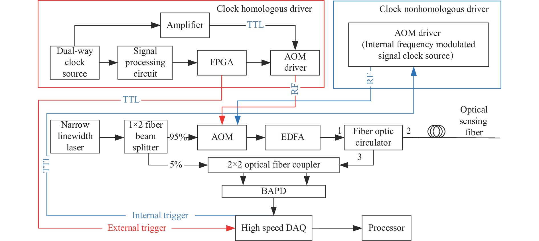
如图5红色实线框所示,设计的时钟同源声光调制驱动器(Clock homologous driver)由双路同步时钟源(Dual-way clock source)、信号调理器(Signal processing circuit)、放大器(Amplifier)、现场可编程门阵列(Field Programmable Gate Array,FPGA)和声光调制器驱动器(AOM Driver)组成。双路时钟源产生频率为
$ {f_{{\text{AOM}}}} $ 的两路同步时钟信号,其中一路经放大器进行功率放大后,作为调制时钟信号,输出给声光调制器驱动器的时钟端口;另一路输出至信号调理器,进行电平调整后,输入FPGA作为时钟信号。FPGA在频率为$ {f_{{\text{AOM}}}} $ 的时钟作用下,产生占空比和频率$ {f_{{\text{PULSE}}}} $ 可调的脉冲斩波信号,输入声光调制器驱动器的脉冲调制端口。声光调制器驱动器在频率调制时钟信号和脉冲斩波信号的共同作用下,产生带脉冲调制的频率为$ {f_{{\text{AOM}}}} $ 的点频激励信号,驱动声光调制器。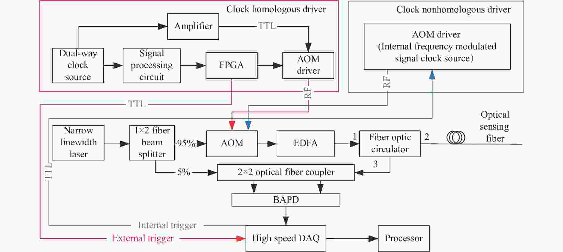
Figure 5. Clock homologous (red) and clock nonhomologous (blue) ϕ-OTDR coherent detection system structure
与图5蓝色框中所示的驱动器具有内部频率调制信号时钟源(Internal frequency modulated signal clock source)的传统时钟非同源驱动(Clock nonhomologous driver)方式,该设计由于频率调制时钟信号和脉冲斩波信号均来自时钟同步的双路时钟源,所以频率调制时钟信号和脉冲斩波信号具有相同的时钟,在每一个脉冲周期内,脉冲调制信号的起始相位不存在沿时间轴的抖动,如图6所示。同时,FPGA输出与脉冲斩波信号同步的触发信号,送给高速数据采集卡,作为数据采集的起始标志信号,使数据采集卡采样时刻与脉冲光起始时刻同步,提高数据采集质量,抑制低频噪声干扰。

Figure 6. Pulse modulation signal curves of the acoust-optic modulation driver after clock homology control
ϕ-OTDR系统其余组成部分为典型外差相干检测结构,窄线宽激光器(Narrow linewidth laser)发出相干连续光,光源中心波长1 550.12 nm,线宽(~1.8 kHz),频率漂移(< 1 MHz/min);经1×2光纤分束器(Fiber beam splitter)分为两路,其中一路光经由声光调制器(Acoustic optical modulator,AOM)移频调制,调制频率为
${f_{{\text{AOM}}}} = 80\ {\rm{MHz}}$ ,转换为具有特定脉冲宽度和重复周期$ 1/{f_{{\text{PULSE}}}} $ 的脉冲光,光波频率为$ {f_c} + {f_{{\text{AOM}}}} $ ,再由输入掺饵光纤放大器(Erbium-doped fiber amplifier, EDFA)进行放大后,进入光纤环形器(Fiber optic circulator)1端口,再通过光纤环形器2端口进入传感光纤,携带光纤沿线扰动信息的后向瑞利相干散射光再次经过光纤环形器2端口,由端口3进入频率响应范围为0~400 MHz的光电平衡放大探测器(Balance amplify photodetector, BAPD);另一路连续光作为本振光,频率与光波频率相同。本振光与后向瑞利相干散射光经过2×2光纤耦合器(Optical fiber coupler)和BAPD后,消除了光波频率$ {f_c} $ ,保留主频为$ {f_{{\text{AOM}}}} $ 的电相干模拟信号,随后进入采样率为1 GS/s高速数据采集卡(High speed data acquisition card),得到的数字信号经I/Q数字相干解调、相位解卷绕等数据处理,获取沿光纤的振动信息[13]。 -
实验采用如图5所示的时钟同源和非同源两种ϕ-OTDR系统结构进行对比与分析,采用信号发生器产生0.1 Hz、10 Hz、500 Hz、1 kHz的5 V信号驱动OPTIPHASE公司生产的PZ1 Fiber Stretcher,其具有极小的电压调制延时,约为0.0007 ps/V,电压变化与调制引起的相位变化具有良好的线性度,且相同调制电压下,在0~2 kHz的频率调制范围内相位响应一致性较高,内部缠绕光纤长度约为10 m,每一伏特电压变化所引起的光纤应变为0.014微应变,将PZT接入长度约为2.5 km的两盘光纤中间位置。
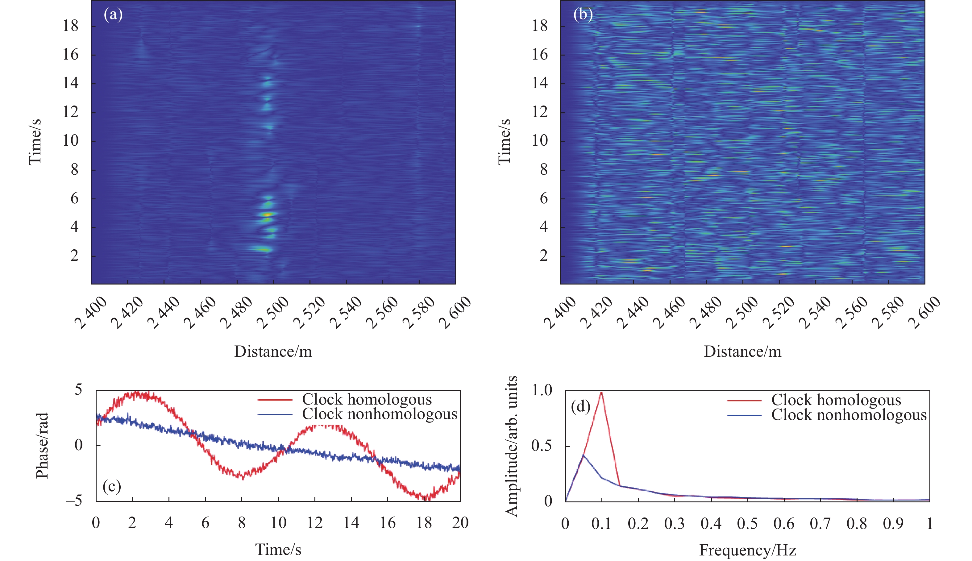
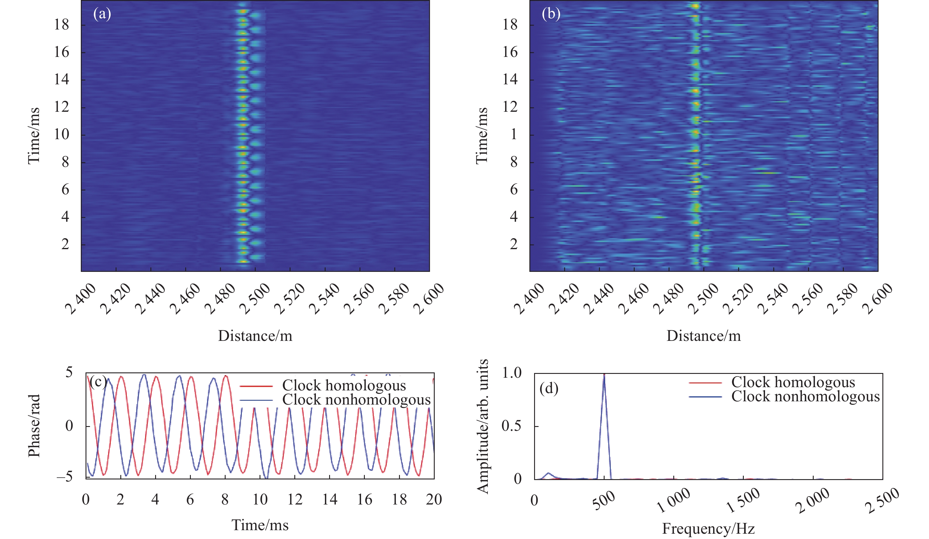
当扰动频率为0.1 Hz时,如图7(a)所示,时钟同源的ϕ-OTDR系统在20 s采样时间内,相对于时钟非同源的ϕ-OTDR系统在扰动位置具有更高的信噪比,与无扰动位置区分度较高,而后者扰动信号淹没于系统噪声中;如图7(c)中红色曲线所示,时钟同源系统可完整恢复20 s内0.1 Hz扰动信号的2个周期,图7(d)中频谱主频位于0.1 Hz,而时钟非同源系统不能够正确解调该频率所引起的相位变化,频谱响应不正确,主要为系统噪声,如图7(d)中蓝色曲线所示。
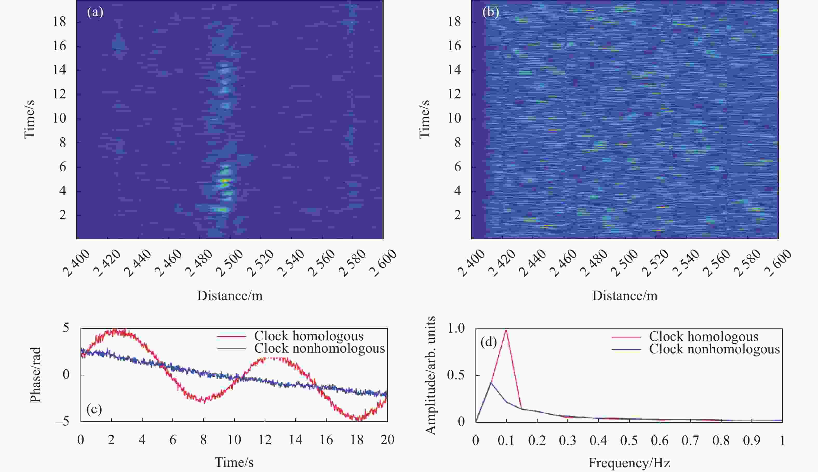
Figure 7. 0.1 Hz disturbance signal. (a) Position-time-intensity response diagram of clock homologous system; (b) Position-time-intensity response diagram of clock non-homologous system; (c) Phase demodulation curve of both; (d) Spectrum diagram of both
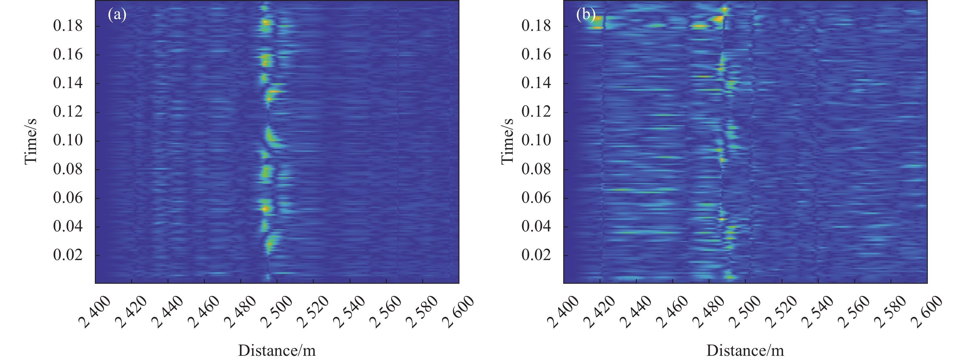
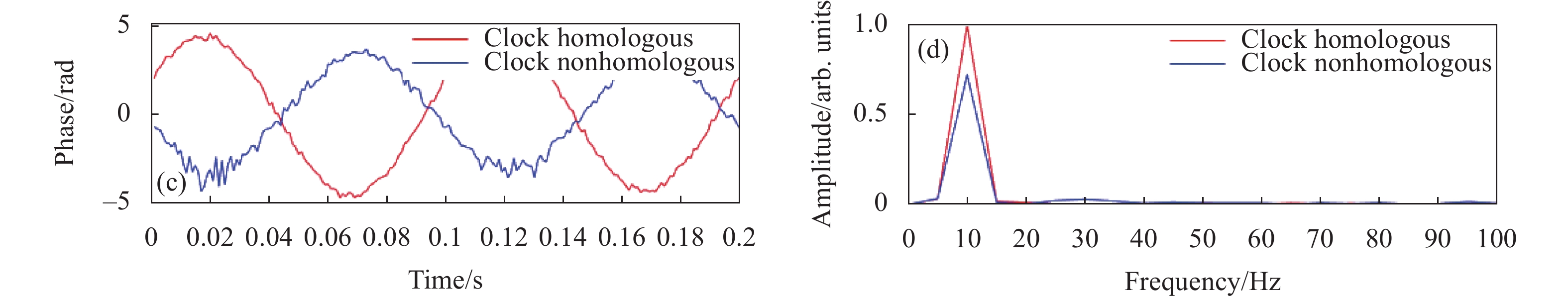
当扰动频率为10 Hz时,如图8(a)和8(b)所示,时钟同源和时钟非同源的ϕ-OTDR系统在0.2 s采样时间内均有响应,依旧是前者的信噪比和扰动事件区分度更高;如图8(c)中相位解调曲线所示,两者均在0.2 s内解调出两个周期的相位变化曲线,但时钟同源系统所对应的红色曲线更为平滑,而图8(d)频谱曲线中,可以看出非同源系统在主频10 Hz的幅值存在衰减,且在50 Hz以内存在一定程度干扰,幅频曲线(蓝色)略高于时钟同源系统的幅频曲线(红色)。
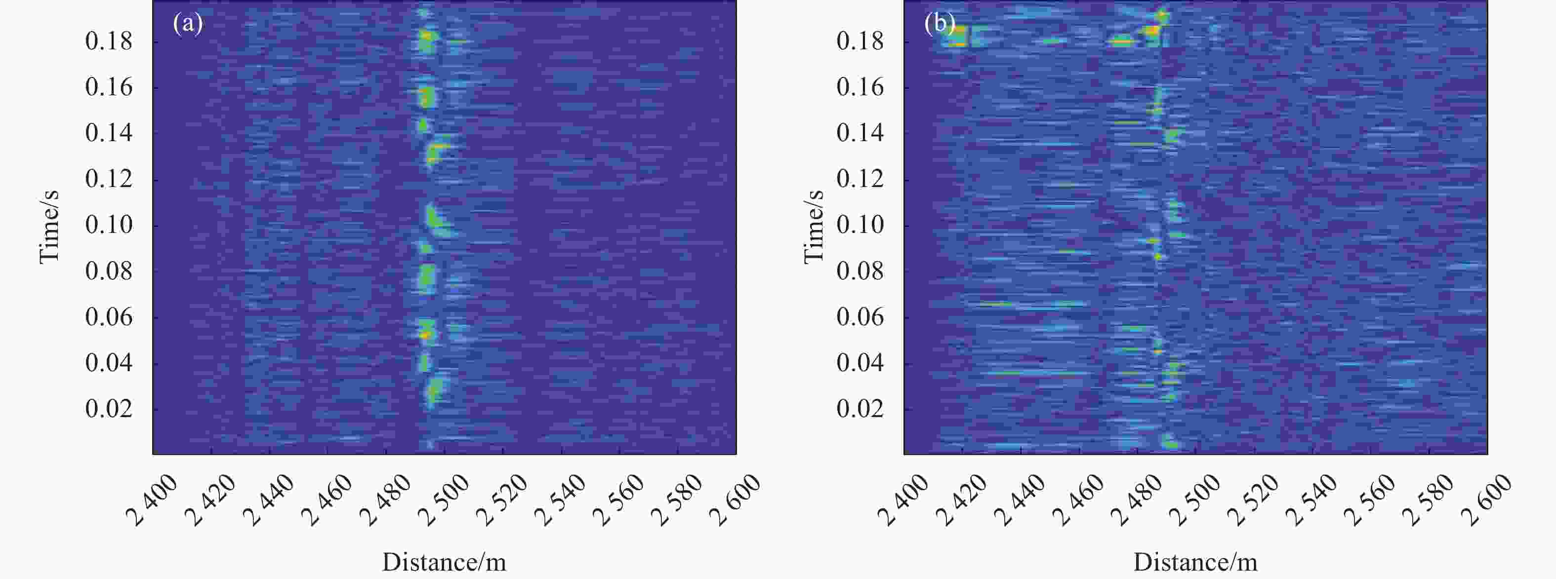

Figure 8. 10 Hz disturbance signal. (a) Position-time-intensity response diagram of clock homologous system; (b) Position-time-intensity response diagram of clock non-homologous system; (c) Phase demodulation curve of both; (d) Spectrum diagram of both
图9(a)、(b)和图10(a)、(b)为时钟同源和非同源系统对500 Hz和1 kHz扰动信号的20 ms内响应结果对比图,从图9(c)和图10(c)可以看出两系统均能够实时响应,并正确解调出相位变化曲线和幅频响应曲线,但前者信噪比更高,较好地抑制了系统低频噪声,如图9(d)和图10(d)中的频谱对比曲线所示,非同源系统的幅频曲线(蓝色)在低频段存在一定程度的干扰噪声。

Figure 9. 500 Hz disturbance signal. (a) Position-time-intensity response diagram of clock homologous system; (b) Position-time-intensity response diagram of clock non-homologous system; (c) Phase demodulation curve of both; (d) Spectrum diagram of both
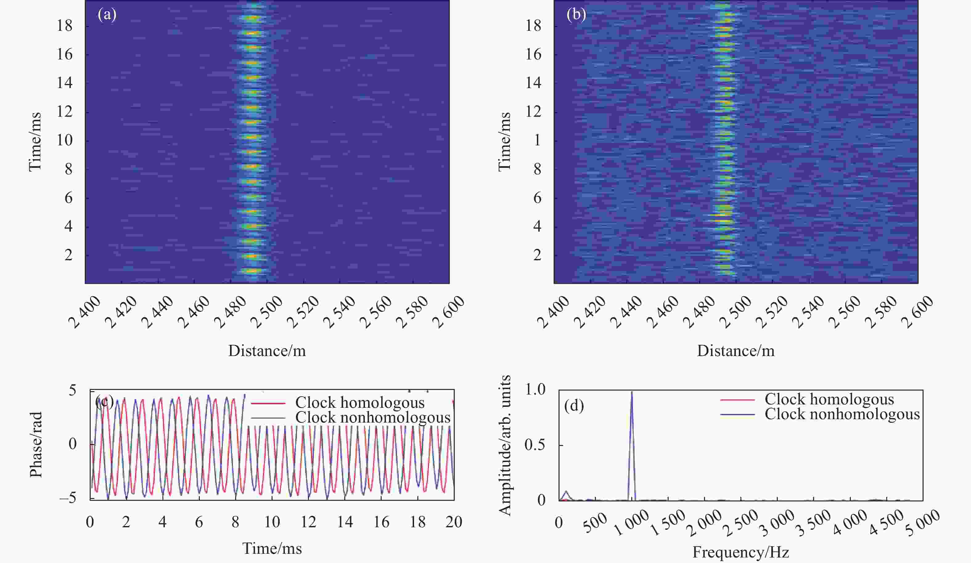
Figure 10. 1 kHz disturbance signal. (a) Position-time-intensity response diagram of clock homologous system; (b) Position-time-intensity response diagram of clock non-homologous system; (c) Phase demodulation curve of both; (d) Spectrum diagram of both
由以上实验结果可知,采用时钟同源控制的ϕ-OTDR系统,解决了原有典型的基于外差相干检测的ϕ-OTDR系统中由于频率调制信号和脉冲斩波信号时钟不同源,由时钟稳定度差异引入的探测脉冲光波初始相位随机抖动问题,提高系统信噪比,有效提高ϕ-OTDR系统的低频响应性能和响应范围。
-
文中对ϕ-OTDR系统中脉冲斩波信号与频率调制信号时钟不同源的问题及其产生的影响进行理论分析,设计双路同步时钟源驱动产生脉冲斩波信号和频率调制信号,降低每个脉冲重复周期中频率调制信号的随机低频相位噪声,提高探测脉冲光的相位稳定性;采用时钟同源和时钟非同源两种方式对典型的基于外差相干检测的ϕ-OTDR系统的声光调制器进行驱动,由信号发生器产生0.1 Hz、10 Hz、500 Hz、1 kHz的信号驱动缠有光纤的压电陶瓷,模拟光纤上不同频段的扰动信号,通过实验对比,时钟同源的系统在信噪比、相位解调质量、频率响应方面均优于传统的时钟非同源系统,最小响应频率为0.1 Hz,降低了低频噪声干扰,优化了系统的低频检测性能。该方法易于实现,可与现有的低频性能优化方法或结构兼容,进一步提高系统在分布式水听、油气微地震检测、自然灾害监测等低频监测领域的适用性。对于连续采集的大数据量低频信号的实时采集、存储、快速显示与并行处理仍为该研究方向的热点之一。
Optimization of low frequency response performance of phase sensitive optical time-domain reflectometry system
doi: 10.3788/IRLA20211125
- Received Date: 2021-12-05
- Rev Recd Date: 2022-01-25
- Accepted Date: 2022-02-23
- Publish Date: 2022-06-08
Fund Project:
Young Innovative Talents Program of Guangdong University(2018 KQNCX332);Introduction of Leading Talents Program of Guangdong Province(00201507);Education Department of Guangdong Province Created Group Project(2018 KCXTD033);Zhongshan Social welfare Science and Technology Research Project(2018 B1021,2020 B2018); Cooperation project between universities in Chongqing and affiliated institutes of Chinese Academy of Sciences(HZ2021014);Major project of Chongqing Education Commission(KJZDM202001401)
-
Key words:
- phase sensitive optical time domain reflectometry /
- clock homology control /
- random phase noise suppression /
- low frequency detection
Abstract: Phase sensitive optical time-domain reflectometry system due to its advantages of distributed optical fiber sensing technology has a high application prospect in low frequency monitoring fields such as distributed hydrophone, fracture micro-seismic detection and natural disaster warning. The problem of different clock source of pulse chopper signal and frequency modulated signal in the system was verified and the influence was analyzed theoretically in this paper. A dual-channel synchronous clock source was designed to generate pulse chopper signal and frequency modulation signal to reduce the random low-frequency phase noise of frequency modulation signal in each pulse repetition period and improve the phase stability of the detection pulse light. The acousti-optic modulator of typical phase-sensitive optical time-domain reflectometry system based on heterodyne coherent detection was driven by clock homology and clock non-homology, a signal generator drives a piezoelectric ceramic wrapped in optical fibers to generate disturbance signals in different frequency bands. The experimental results show that under the same test conditions, the former is superior to the latter in the aspects of SNR, phase demodulation quality and frequency response in low frequency band. The minimum response frequency is 0.1 Hz, which is 2 orders of magnitude higher than the latter, and reduces the interference of low frequency noise in the system. The method was easy to implement and compatible with the existing low frequency performance optimization methods or structures to further improve the low frequency response performance of the system.


 DownLoad: