


-
近年来,随着微纳遥感卫星星座的发展,对空间光学相机的尺寸和质量提出了更为严格的要求,需要轻量化程度更高的光机结构来进一步实现紧凑型光学遥感相机的设计[1]。轻量化程度高的设计不仅要在结构性能和质量参数间进行权衡,还将导致光学相机对于重力、振动和冲击等力学条件更为敏感,易受工作环境影响而引起光学系统成像质量的下降。对于同轴空间相机来说,主支撑结构用于固定主镜与次镜的相对位置关系,而主镜与次镜的系统失调量会影响相机成像质量[2]。所以,空间相机的主次镜支撑结构设计及分析技术一直是国内外学者研究的重点[3-4]。董得义等人[5]采用集成仿真分析的方法对空间离轴相机在重力载荷作用下的系统波像差变化进行了研究,并在装调完成后进行了翻转前后的波像差对比测试。
基于有限元方法,采用拓扑优化、尺寸优化等方式对主支撑结构进行优化设计是一种普遍应用的结构设计方法 [6]。多学科设计优化是一种处理复杂耦合系统的集成分析方法、已被广泛应用于微纳卫星的总体设计[7]。对于轻量化相机的光机结构优化设计,越来越多的学者采用光机集成分析的方式在设计过程中以保证光学成像性能为约束条件之一进行系统级闭环分析[8-9]。采用光学、结构、热学软件集成仿真的方式进行集成仿真分析,设定好软件间的交互接口和文件,即可分析系统在力学、热学条件下的成像性能。然而,软件间的仿真计算量大、数据交互不方便,不利于在优化设计阶段的仿真迭代[10-11]。
为了在优化迭代设计过程中提高方程解算效率,一般会采用线性近似的方式来建立模型来代替仿真软件 [12]。光学线性模型经常被用于快速地根据光学元件的状态对成像性能和视轴稳定性进行预测。Howard[13]系统地总结了James Webb 空间望眼镜在2003~2009年的开发过程中进行光机热集成建模与分析所采用的光学线性模型和集成分析方法。Riva[14]提出了基于光学追迹构造光学灵敏度矩阵来改进光机结构的优化设计方法。Keith等人[15]基于Zernike多项式构建了光学表面变形相对于波像差的灵敏度模型。Blaurock[16]介绍了在光机热集成分析中的灵敏度计算方法。
目前对于同轴式空间相机多采用桁架式主支撑结构来实现高轻量化率设计[7,17],为了保证结构的力学稳定性,桁架支撑结构通常采用三根以上的桁架杆组成支撑系统,存在遮拦比大和工艺难度大等问题。文中针对空间微纳光学遥感相机所采用的单悬臂式支撑结构优化设计与验证需求,开发了用于其力学条件下成像质量研究的集成分析方法。依据系统波像差与光机结构失调量的灵敏度构建光学线性模型,相比于传统集成仿真分析,该方法能够通过光学线性模型直接对结构分析结果进行处理得到波像差的变化,在光学系统设计不更改的条件下,集成分析过程中不需要再进行光学软件的操作,流程相对简单、效率高。采用所提出的方法对所设计的支撑结构进行了重力工况下的集成仿真分析和实验验证。
-
光学元件在力学和热学条件作用下会产生相应的变形,主要包括表面的高阶变形与元件的刚体位移。其中,刚体位移主要包括光学元件在空间六个自由度的平移和旋转,这些位移会使该元件相对于光学系统产生离轴、偏心和倾斜等误差,这些误差会进一步降低光学系统的波像差。定义刚体的平移和旋转运动如下:
(1) 沿坐标系的平移运动Dx,Dy,Dz (Dx和Dy为偏心运动,Dz为离轴运动);
(2) 沿坐标系的旋转运动Tx,Ty,Tz(Tx和Ty为倾斜运动,Tz为旋转运动)。
在分析过程中,为了快速计算扰动条件下所产生的元件刚体位移对于系统波像差的影响,假设系统波像差是光学元件刚体位移量的线性函数,即系统波像差能够直接通过光学灵敏度系数和元件的刚体位移量相乘计算得到。也就是说,灵敏度系数直接反映了系统波像差对元件刚体位移误差的敏感程度,即:
式中:i和j分别表示光学元件和自由度编号;D代表光学元件某一自由度上的刚体位移失调量;L代表光学元件在该自由度失调量的灵敏度;W为由D失调量引起的系统波像差。
考虑所有光学元件各自由度方向上的系统失调量引起光学系统整体波像差的变化为:
上式的灵敏度矩阵是光学系统的固有属性,不仅可以指导光学系统的设计和误差分配,还可以应用在光机集成分析中,对光学系统波像差进行快速计算。光学灵敏度系数的计算可以使用光学设计软件进行,通过手动添加每个元件/表面的刚体扰动并计算相应的系统波像差变化来获得。
-
光学元件的刚体位移不能直接计算得到,一般采用有限元法对光学元件进行离散后,光学元件由有限元节点和网格来表示,而通过对有限元结果的后处理得到变形后元件的刚体位移。元件在六个自由度上的刚体运动而产生的第i个节点的平移为:
式中:xi,yi,zi为
第i个节点的坐标位置。 有限元分析完成后,采用最佳拟合(best-fit)算法对结果进行后处理,从元件所有节点的变形中提取刚体位移。定义误差函数
式中:wi为权重函数;(dxi, dyi, dzi)为有限元计算得到的变形后的节点i的坐标;(
${\rm{d}}{\tilde x_i}$ ,${\rm{d}}{\tilde y_i}$ ,${\rm{d}}{\tilde z_i}$ )为使用公式(2)计算刚体运动后的节点i的坐标。通过求函数E的最小值来确定光学元件表面的刚体位移。 -
集成仿真分析流程如图1所示。根据光学分析手段的不同,光机热集成仿真分析可以分为两种。一种是全部基于商业软件工具,按照流程逐级进行仿真分析,有限元分析软件根据力学或热学载荷计算得到光学元件变形后的节点坐标位置,对该结果数据进行后处理得到光学元件的高阶表面变形及刚体位移,并基于这些失调量对光学分析软件中的元件模型进行相应修改,最终分析得到在该扰动条件下的系统性能变化。另一种是直接基于光学系统的灵敏度分析结果获得光学线性模型,在得到光学元件的位移后根据灵敏度方程获得系统性能的变化。
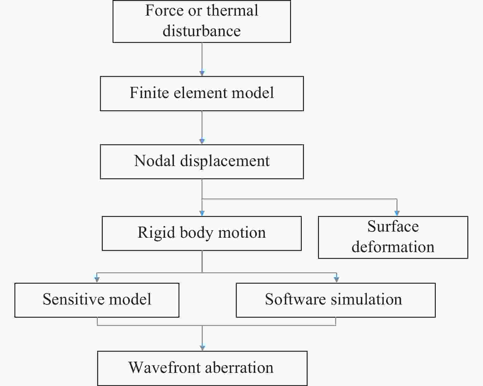
Figure 1. Flow diagram of opto-mechanics integrate simulation
-
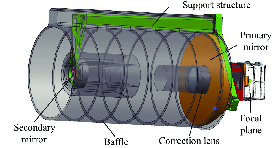
空间相机运行在500 km的轨道高度上,相机质量在5 kg以内,并具有全色、RGB 以及近红外五个谱段。光学系统采用同轴两反加校正镜的形式。该相机由于光学系统的跨距较大,同时镜头口径较大,采用传统的承力筒或桁架式结构很难满足相机的质量要求。因此采用单杆支撑作为主承力结构,其设计过程困难、复杂,仅应用在部分国外的空间遥感相机上,如日本/欧盟联合开发的地球云和气溶胶辐射探测卫星(EarthCARE)中的大气激光雷达(ATLID)相机及美国研制的GIFTS无焦望远镜。单杆主承力结构由主承力板、主支撑杆及次镜支架三部分组成,如图2所示。
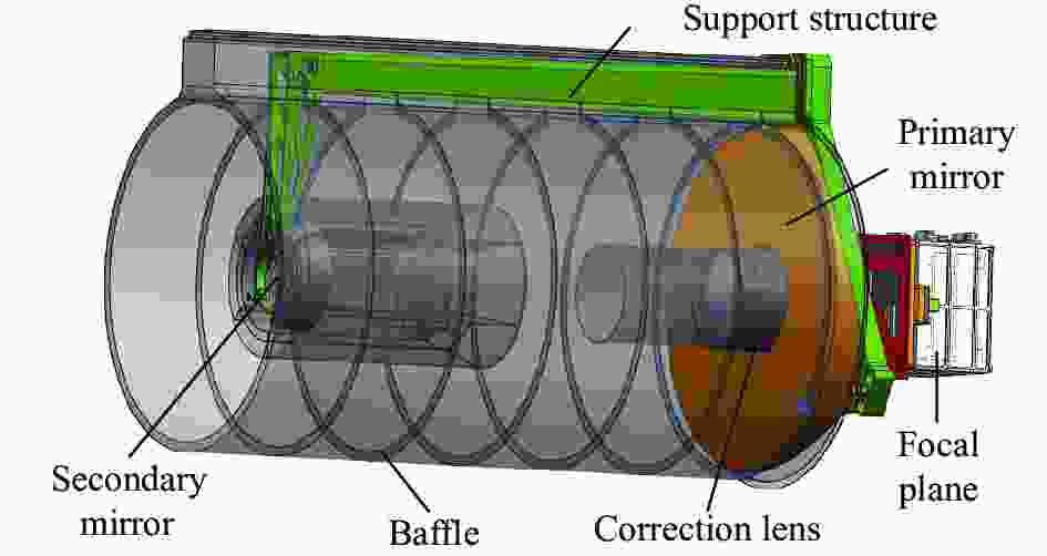
Figure 2. 3D model of space camera
-
光学系统设计完成后,为了得到主镜(primary mirror, PM)、次镜(secondary mirror, SM)失调量对于系统波像差的影响,从而指导光机系统的设计,分别进行了主镜、次镜在平移和旋转方向的波像差灵敏度分析。平移和旋转的单位失调量增量分别设置为1 μm和1″。通过分别分析主、次镜各失调量引起的光学系统波像差,获得在各个失调位置处对应的系统波像差,并将结果绘制如图3和图4所示。
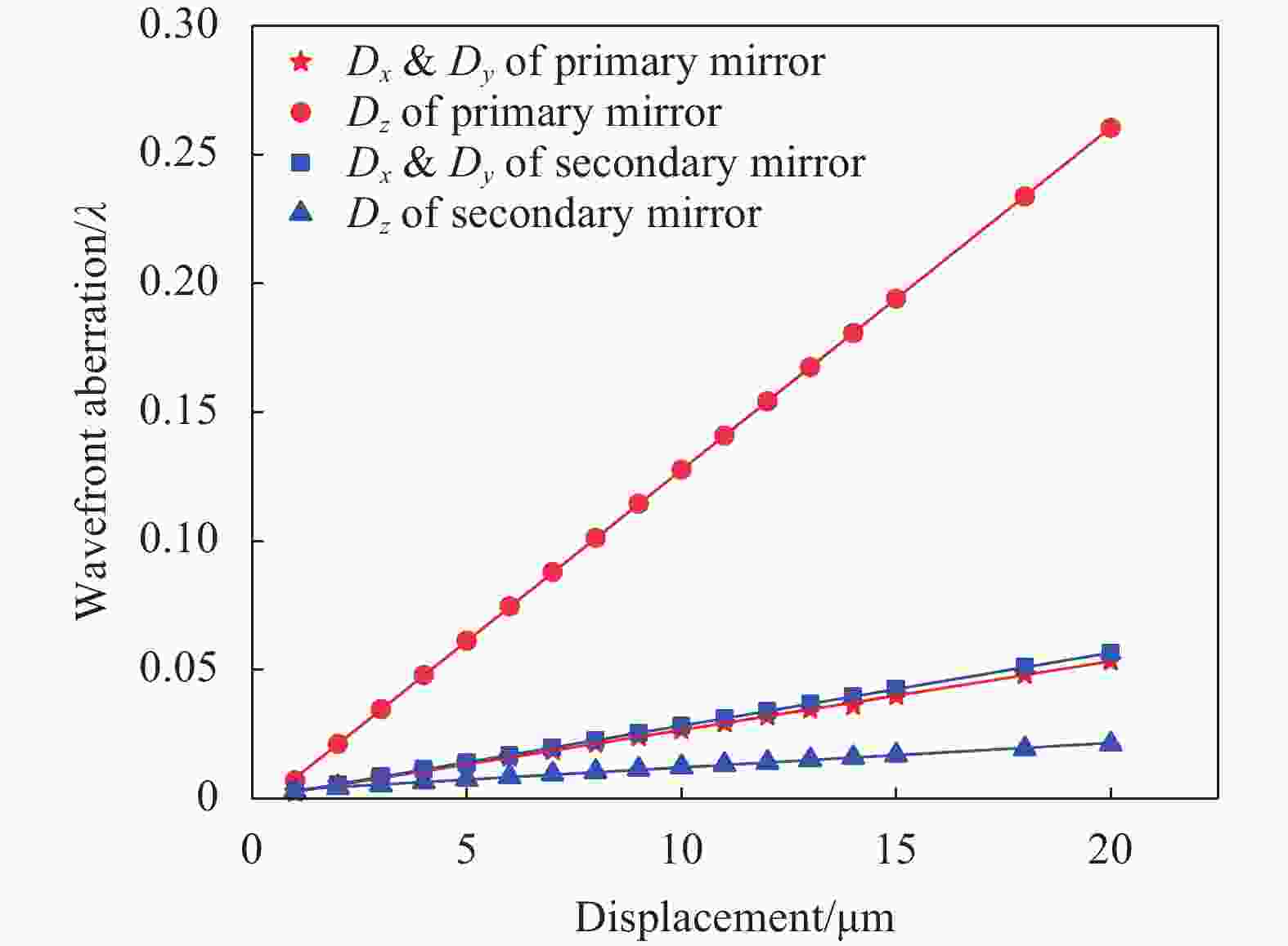
Figure 3. Relationship between displacement and wavefront aberration of primary mirror and secondary mirror

Figure 4. Relationship between tilt and wavefront aberration of primary mirror and secondary mirror
可以看出,主镜和次镜的位移和倾斜失调量与系统波像差具有非常好的线性关系,根据平面直线公式进行拟合,得到各线性关系的斜率和截距如表1所示。
Misalignment Sensitive
(λ/μm; λ/(″))Intercept/λ PM-Dx 2.67E-03 5.16E-06 PM-Dy 2.67E-03 5.16E-06 PM-Dz 1.33E-02 5.29E-02 PM-Tx 6.35E-03 −3.90E-06 PM-Ty 6.35E-03 −3.90E-06 SM-Dx 2.84E-03 −1.33E-05 SM-Dy 2.84E-03 −1.33E-05 SM-Dz 9.55E-04 2.67E-03 SM-Tx 8.75E-04 −1.85E-04 SM-Ty 8.75E-04 −1.85E-04 Table 1. Fitting parameters
-
光机结构有限元模型如图5(a)所示,网格数量为137337,重力方向为−X方向。其在重力条件下的静力学变形云图如图5(b)所示。对有限元分析结果进行后处理,提取主镜和次镜的有限元节点坐标及位移量,进行叠加得到变形后的节点坐标位置,并分别使用主镜和次镜表面的节点基于公式(3)和公式(4)进行主镜和次镜六个方向刚体位移的计算,结果如表2所示,其在X方向的平移量和绕Y方向的旋转量与变形云图一致。将主镜和次镜的刚体位移量分别与表1中对应的灵敏度系数相乘,得到每个位移量引起的系统波像差变化如表2所示。并基于公式(2)计算得到系统波像差变化为0.0569λ。
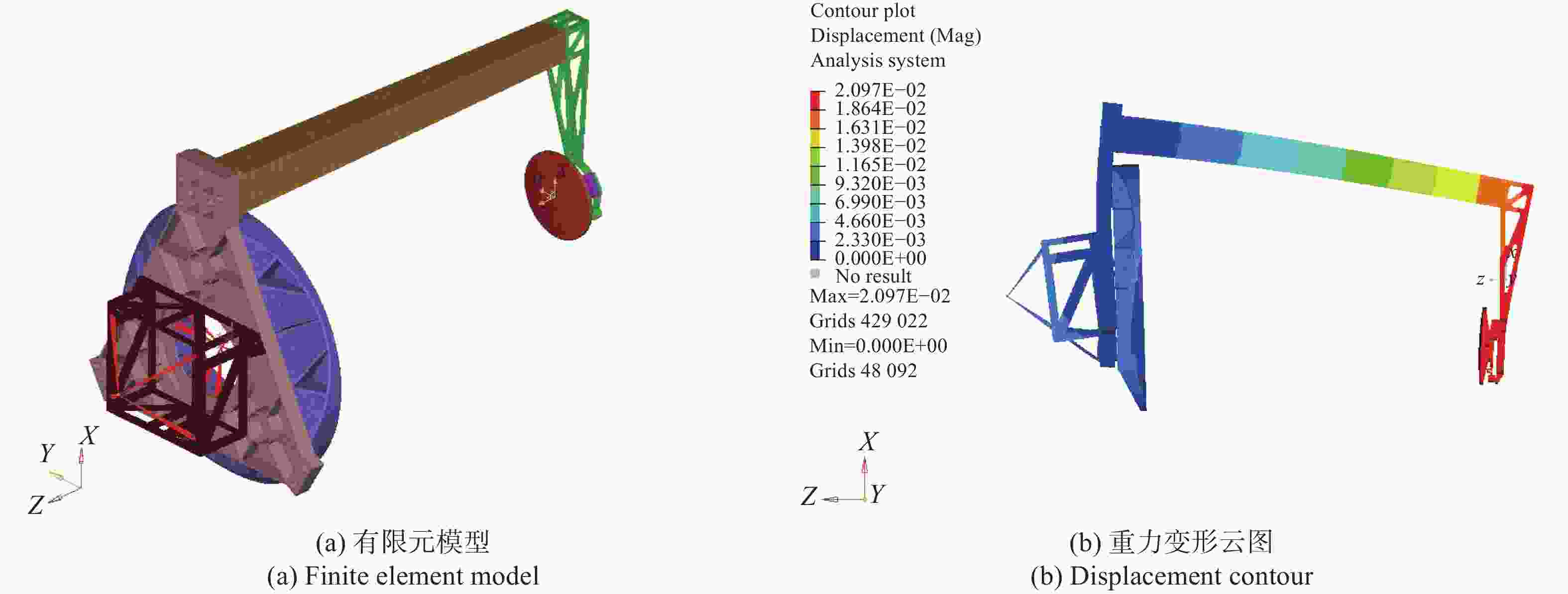
Figure 5. Finite element model (a) and displacement contour (b)
Subassembly Direction Dx Dy Dz Tx Ty Tz PM Misalignment/mm; (″) −2.324E-03 1.233E-06 3.684E-04 −1.63E-06 4.70E-04 2.075E-08 Wavefront aberration/λ 6.20E-03 3.29E-06 4.90E-03 3.73E-05 1.07E-02 0 SM Misalignment/mm; (″) −1.903E-02 −1.415E-04 7.777E-03 3.59E-06 −6.83E-04 8.248E-07 Wavefront aberration/λ 5.40E-02 4.01E-04 −7.38E-03 1.13E-05 −2.15E-03 0 Table 2. Rigid body displacements of primary mirror and secondary mirror
最后,为了进行对比,根据表2中主镜和次镜的刚体位移量修改光学软件中的主镜和次镜的位置和倾斜量,进行分析得到重力条件下的系统波像差为0.0487λ,如图6所示,可见该光机结构的设计具有非常好的静刚度,使主镜和次镜的位移量和角度偏移量都非常小,从而使重力对光机系统成像质量的影响非常小。基于公式 (5)计算所提出方法相对于软件仿真结果的误差为16.8%,说明灵敏度分析具有足够的精度,在初步设计阶段用于快速对系统波像差预测。
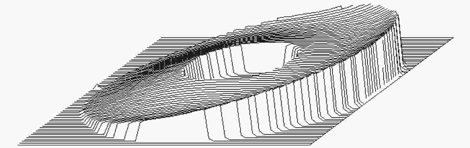
Figure 6. Optical software analysis results
式中:WE 为两种方法的计算误差;WM为基于灵敏度分析模型的波像差计算结果;WS为基于软件仿真的波像差计算结果。
-
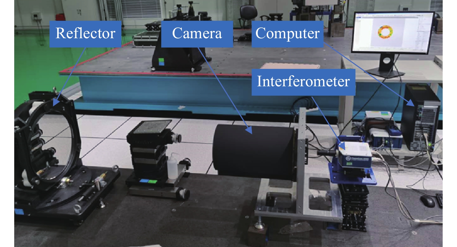
装调后的光机系统采用自准方法进行各视场波像差的检测。如图7所示,在相机焦面位置放置干涉仪,相机入光口处放置平面反射镜,干涉仪发出的光经过光学系统,经平面反射镜反射后再入射到光学系统中,光线原路返回至干涉仪中产生干涉条纹,从而进行波像差检测。为了进一步验证所设计的主承力结构的性能对系统波像差的影响,分别进行了正向和反向重力工况下的波像差测试。其中,反向重力工况为相机倒置稳定后进行波像差测试。

Figure 7. Wavefront aberration measurement setup
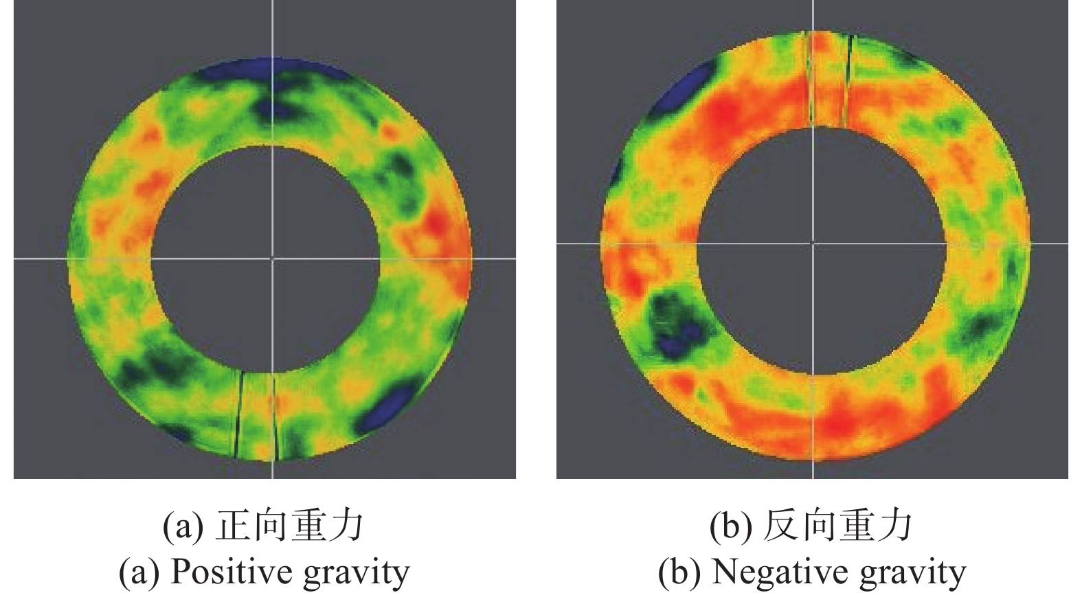
图8所示为两种工况下的中心视场波像差测试结果,并汇总于表3中。可见系统波像差在正向和反向重力工况下的差别非常小,最大误差在10%以内,证明了光机结构具有非常好的力学稳定性。
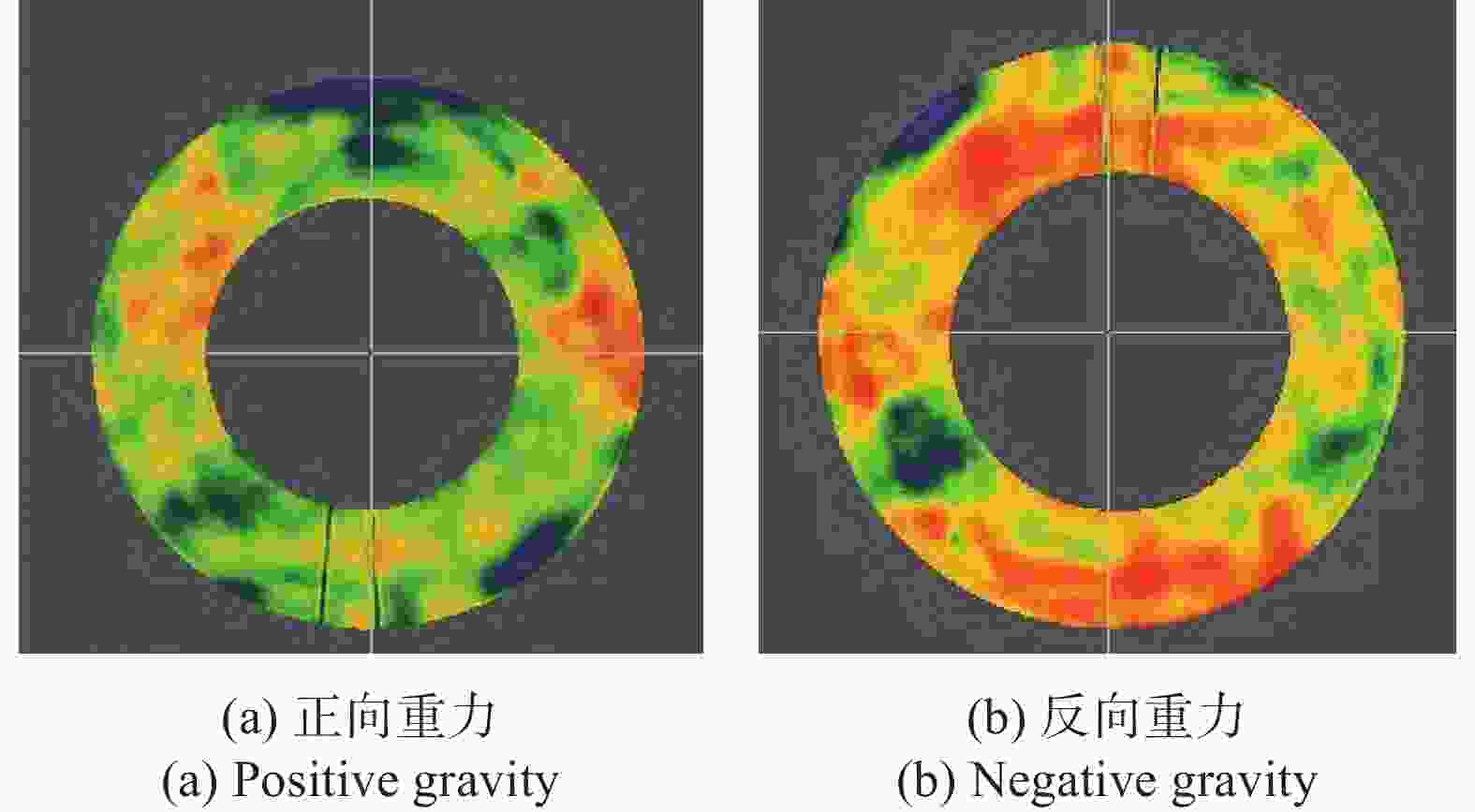
Figure 8. Wavefront aberration measurement results of central field of view
Direction Positive/λ Negative/λ Error Central FOV 0.0531 0.0518 −2.45% Right FOV 0.0748 0.0814 8.82% Left FOV 0.0683 0.0694 1.61% UP FOV 0.06543 0.0639 −2.34% Down FOV 0.0539 0.0565 4.82% Table 3. Wavefront aberration measurement results
-
根据微纳航天遥感相机在保证成像质量条件下的轻量化设计需求,介绍了一种新型单杆主承力结构,并提出了以波像差灵敏度分析法指导光机结构的快速优化设计,以光机集成仿真分析进行设计验证的研制方法。然后通过正、反重力工况的波像差测试,对所设计的主承力结构稳定性进行了验证。结果证明,灵敏度分析方法相对于光机集成软件仿真方法误差为16.8%,其精度满足在初步设计优化阶段快速对系统性能进行预测的需求。使用该方法所设计的轻量化微纳遥感相机在地面正、反重力工况下各视场波像差差别较小,波像差最大变化在10%以内,说明系统成像性能优异且具有非常好的力学稳定性能。
Wavefront aberration sensitivity and integrated analysis method for spaceborne camera
doi: 10.3788/IRLA20220109
- Received Date: 2022-02-17
- Rev Recd Date: 2022-05-07
- Publish Date: 2022-11-30
-
Key words:
- micro-nano satellite /
- spaceborne camera /
- optomechanical integrated optimization /
- mechanical performance /
- wavefront aberration
Abstract: Aiming at a new type of single cantilever main support structure of space camera, both wave aberration sensitivity model and integrated simulation analysis are proposed to calculate the camera's wave aberration in the lightweight design of optomechanical structure, so as to ensure the imaging quality under mechanical conditions. The proposed wave aberration sensitivity method can model based on the linear relationship between wave aberration and misalignment, which is of great significance to guide the optimal design of optomechanical structure under the constraint of the camera imaging quality. Firstly, the sensitivity model of optical element misalignment and wavefront aberration is derived based on the principle of optical system misalignment. Then, the nodal displacements under mechanical condition are obtained by finite element method, and the misalignment of primary and secondary mirrors is calculated based on best-fit fitting method. The wavefront aberration of the camera is obtained by the optical analysis of the misaligned system. Finally, the two methods proposed in this paper are used for modeling and analysis of a 5 kg level space optical camera, and the corresponding gravity condition analysis and test are also performed. The error of sensitivity model is 16.8% compared with the optomechanical integrated simulation method, and the sensitivity model can be applied to the rapid calculation of system imaging performance in the design phase.


 DownLoad: