


-
光学自由曲面是非球面的一种特殊形式,在狭义上是指表面各处曲率不同的光滑光学曲面。在军工或民用领域,拥有了更大自由度的光学自由曲面在成像[1-2]、照明[3]等领域给设计者带来了极大的施展空间,极大地提升了光学产品的性能。但同时因其高自由度的特点,也给自由曲面制造[4]尤其是面形的高精度检测增大了难度[5-6]。对于公认精度最高的干涉检测方式来说,检测时需要一个能够全部或部分补偿被测自由曲面像差的光学补偿器。由于自由曲面表面自由度大,传统补偿器的设计复杂且不能保障可被加工。针对性地实现波前补偿的计算全息图(CGH)[7-8]可以充当这个角色但其不具通用性。同时,在实际高精度光学制造中,面对迭代制造过程中不断被修正的面形,需要一种可以产生大动态像差范围和具有灵活像差调控能力的补偿元件,显然CGH不具有这种能力。
若干具有一定波前动态像差范围的补偿器曾在非球面检测中被提出,如微透镜阵列[9]、可变零位器[10]、可移动高次非球面单透镜[11]和双回转相位板[12],但上述补偿器像差调控类型和能力也均有限,并不能实现真正意义上的自由像差调控。由于自适应光学元件具有可编程控制的波前调控能力,如液晶空间光调制器(LC-SLM)和可变形镜(DM),因此Arizona大学[13]、Rochester大学[14-15]、清华大学[13]、国防科技大学[16]和安徽大学[17]均展开了基于LC-SLM或DM的自适应干涉检测研究。但目前实验验证的报道中,基于DM的自由曲面检测动态范围和检测精度略高于LC-SLM (受限于灰度级和调控算法),且DM作为反射器件,波前调控和光学追迹简单,无波长选择性,可与各种波长的干涉仪配合使用,因而作为动态补偿器在自由曲面干涉检测中具有较好地应用前景。
然而,DM的传统应用领域为大气光学[18]等自适应像差调节系统,其表面波前调控精度不能满足高精度光学测试的要求。所幸由于其直接反射特性,通过监测DM表面形变可以精确预知其波前调控精度。2014年,Rochester大学[14]预先使用ZYGO干涉仪对DM表面形变标定,但这种非实时、非原位监测过程中容易造成DM形变蠕动,影响最终的检测结果。之后,清华大学和安徽大学对该问题均进行了一系列研究,采用了如相位偏折测量系统(DS)[13],双通道干涉仪[17]等手段对DM进行了实时原位监测。其中,DS在监测DM面形时存在系统校准复杂的问题,更重要的是,无论以何种方式进行DM监测,系统都存在一个基本矛盾:加工过程中不同时段被测面面形相差较大,需要作为补偿器的DM具有较大行程实现大像差覆盖,而DM本身的形变同样需要被监测来保证精度,增大DM的形变量将增加其自身负担。
基于以上研究现状,研究者希望能够在干涉检测系统中使用不超过监测范围的DM形变量去产生更大动态范围的像差补偿,课题组前期提出了一种自适应环形补偿器(ARCC)[19],对重复利用DM形变产生大畸变波前的思路进行了初步验证。考虑到实际工程中应用的自由曲面多数为低阶像差面,文中在ARCC可行性的基础上做出了必要的低阶像差(像散、彗差和球差)补偿研究。通过仿真实验进行了ARCC与传统单次往返式补偿器(TSRC)低阶像差补偿能力对比,同时研究了ARCC对于低阶像差的补偿特性。最后在实际实验中验证了ARCC对于低阶像差的补偿优势,为现实应用提供了理论基础。
-
基于补偿结构为ARCC与TSRC的自适应干涉检测系统原理如图1所示,两种补偿结构均可搭配偏振干涉仪PI工作,图1(a)左侧示出了偏振干涉仪PI的工作原理。PI中激光器发出偏振方向与x轴夹角为
$ \theta $ 的线偏振光,经BS1后分为两束,反射光线作为参考光,透射光线作为检测光。检测光经过补偿结构ARCC或TSRC到达被测面并被反射后,将携带被测面面形信息回到PI,此时检测光的偏振方向为p偏振方向,调整可旋转偏振片(RP)至透振方向与p偏振方向平行(RPy)便可获得检测光与参考光形成的检测干涉图。与此同时,补偿结构ARCC和TSRC设置的另一路监测DM表面形变的s方向线偏振光也可进入PI,可称其为监测光,通过旋转RP至透振方向与s偏振方向平行(RPx)便可获得监测光与参考光形成的监测干涉图。在自适应补偿之前,DM表面处于初始化状态,监测干涉图如I1所示,此时若直接对大偏离度自由曲面进行检测,可能会导致检测干涉图的局部区域因干涉条纹过密而不可见,造成检测信息缺失,如I2所示。运行自适应算法[13,17,19]后,计算机能够自动识别检测干涉图中的条纹不可见区域(条纹过密区域)并向DM发送反馈命令,使其驱动表面形变补偿被测面像差直至检测干涉图达到近零位状态,如干涉图I4所示,从而可完整获取全口径的检测波面信息进行检测路精确建模。同时,自适应补偿结束后的监测(DM)干涉图也在CCD可解析范围之内,如I3所示,通过I3可求解出此时的DM面形,然后将其代入检测路模型,利用光线追迹就可得到被测自由曲面的面形误差。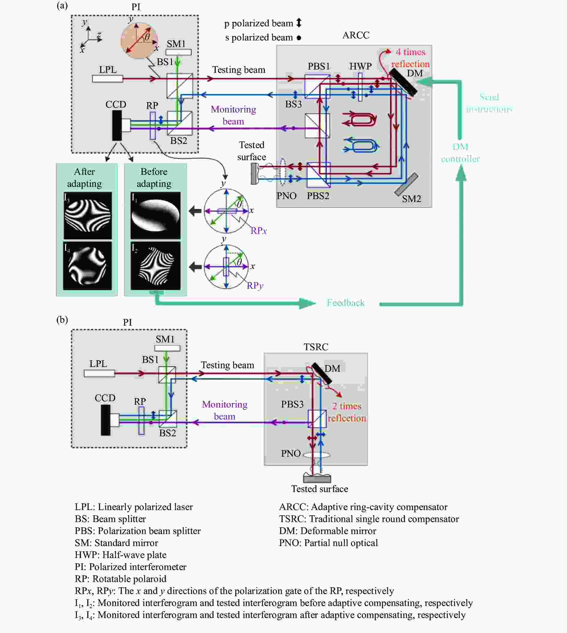
Figure 1. Principle of adaptive interferometer. (a) ARCC-based adaptive interferometer; (b) TSRC-based adaptive interferometer
ARCC补偿结构的详细光路如图1(a)右侧所示。由PI发出的检测光束首先进入ARCC的偏振分束器PBS1成为P偏振光,由于半波片HWP的快轴方向与p偏振方向呈45°,p偏振光经过HWP后偏振方向旋转90°变为s偏振光,s偏振光随后经DM、SM2、PBS2反射到达BS3,此时监测DM表面形变的光线将会被BS3反射到PI中,调整RP~RPx状态时便可获得监测干涉图I2。透射光则不改变传播方向到达PBS1并被全部反射,再次经过HWP后s偏振光的偏振方向旋转90°变回p偏振光。p偏振光然后经DM、SM2表面反射和PBS2全部透射后到达被测表面,此时入射波前已被DM调制了两次。若检测球面基底的自由曲面需要在PBS2后放置部分零位光学元件(PNO),检测平面基底的自由曲面则不需要。到达被测面的p偏振光经被测面反射后会原路返回到PI中,返回的路径中检测波前再次受到了两次DM的形变调制,调整RP至RPy状态时便可获得检测干涉图I1。检测光进出ARCC的整个过程,检测光波前总共经过了DM表面形变的4次调制。另外,由于实际中遇到的被测面反射率不尽相同,需要使用合适透反比的分光棱镜以及入射光偏振方向来保证检测光、监测光分别与参考光之间的振幅比,进而保证干涉条纹的对比度。ARCC结构搭配PI的光能利用分析已在参考文献[19]详细给出,在BS1与BS2透反比均为1的情况下获得高对比度条纹的条件为:
式中:
${t_{{\rm{BS3}}}}$ 为BS3的透射率;$ {r_{{\text{TS}}}} $ 为自由曲面的反射率;$ {r_{{\text{SM1}}}} $ 为SM1的反射率;$ \theta $ 为入射线偏振光与x轴的夹角。当被测面反射率$ {r_{{\text{TS}}}} \geqslant 98 {\text{%}} $ 时,可选择$ {r_{{\text{SM1}}}} \geqslant 98 {\text{%}} $ ,${t_{{\rm{BS3}}}} = 70 {\text{%}}$ 和$ \tan \theta = 5/3 $ 来保证高对比度干涉条纹[19];当被测面反射率低至4%时,应当更换低反射率SM1来降低参考光能量从而分别提高其与监测光和检测光的振幅比,$ {r_{{\text{SM1}}}} = 6 {\text{%}} $ ,${t_{{\rm{BS3}}}} \approx 86 {\text{%}}$ ,$ \tan \theta \approx 0.22 $ 的条件可保证条纹高对比度。TSRC型补偿结构的光路如图1(b)右侧所示,左侧为PI。PI中透过BS1的检测光经DM反射到达PBS3后分成s方向偏振的反射光和p方向偏振的透射光,同样地,反射光将会进入PI记录DM表面形变,透射光则会继续传播到被测面,可以根据被测面的基底类型在被测自由曲面前面选择是否加入PNO,p偏振光被被测面反射后,将会携带被测面面形信息依次经PBS3全部透射和DM反射回到PI。面对实际中不同反射率的被测自由曲面,在BS1与BS2透反比分别为1和1/2,线偏振入射光与x轴夹角
$ \theta $ 为45°时,只需被测面与SM1反射率保持相同即可获得高对比度干涉条纹。检测光进出TSRC的整个过程,检测光波前总共经过了DM表面形变的2次调制,相比ARCC少了一半。根据上述ARCC原理,若将ARCC中HWP的快轴方向旋转到与p偏振方向平行后,检测光全程也将受DM表面形变的2次调制,将变成TSRC型补偿结构。 -
为了验证ARCC相比TSRC在低阶像差补偿方面的优势以及分析ARCC的低阶像差的补偿特性,利用光学追迹软件Zemax进行了仿真实验。实验通过给两种结构中的DM预设相同并具有一定大小的单一低阶像差形变,然后分别优化两种结构中的被测面至剩余波前像差至某一极小水平(
$ {\text{rms}} \approx 0{\lambda} $ )后,通过对比两个被测面上相应的低阶像差大小即可得到两种补偿器对于低阶像差的补偿能力大小。例如预先给两种结构中的DM表面均施加5$ {\lambda} $ 大小的 X像散,然后优化各自对应的被测面面形使得从补偿器出射波前的剩余像差$ {\text{rms}} \approx 0{\lambda} $ 后,便可通过对比两个被测面上X像散量大小得出两种补偿结构对X像散补偿能力的大小。同时,在系统剩余像差$ {\text{rms}} \approx 0{\lambda} $ 的条件下,被测面处的检测波前形状与被测面面形匹配,便可利用被测表面的像差分布进行补偿结构的低阶像差补偿特性分析。仿真实验中DM的参数按照实际商用的AlpaoTM 97-25设定,DM口径设为25 mm,归一化半径为12.5 mm。被测面口径12 mm,并且为平面基底。DM和被测面的附加面形均用条纹Zernike表示。由于DM形变量有限,因此以监测处的最大波前斜率不超过0.35$ {\lambda}/{\text{pixel}} $ 来限定DM表面所施加的像差范围(CCD分辨率为128$ \times $ 128),并且此范围要在AlpaoTM 97-25的GUI菜单提供的像差区间内,结果以整数波长计量。 -
根据前述方法对表1给出的低阶像差范围执行被测面面形的优化,最终优化结果显示系统的剩余像差rms值均在0.02
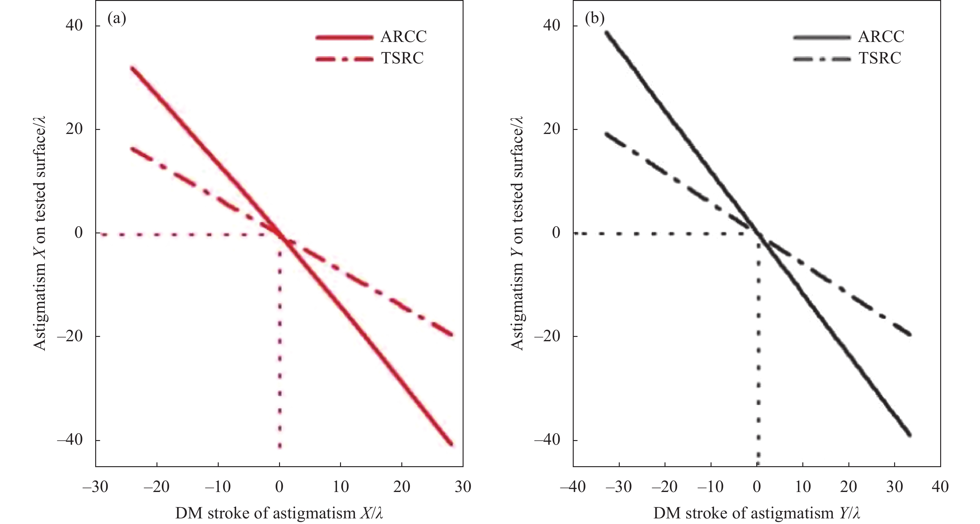
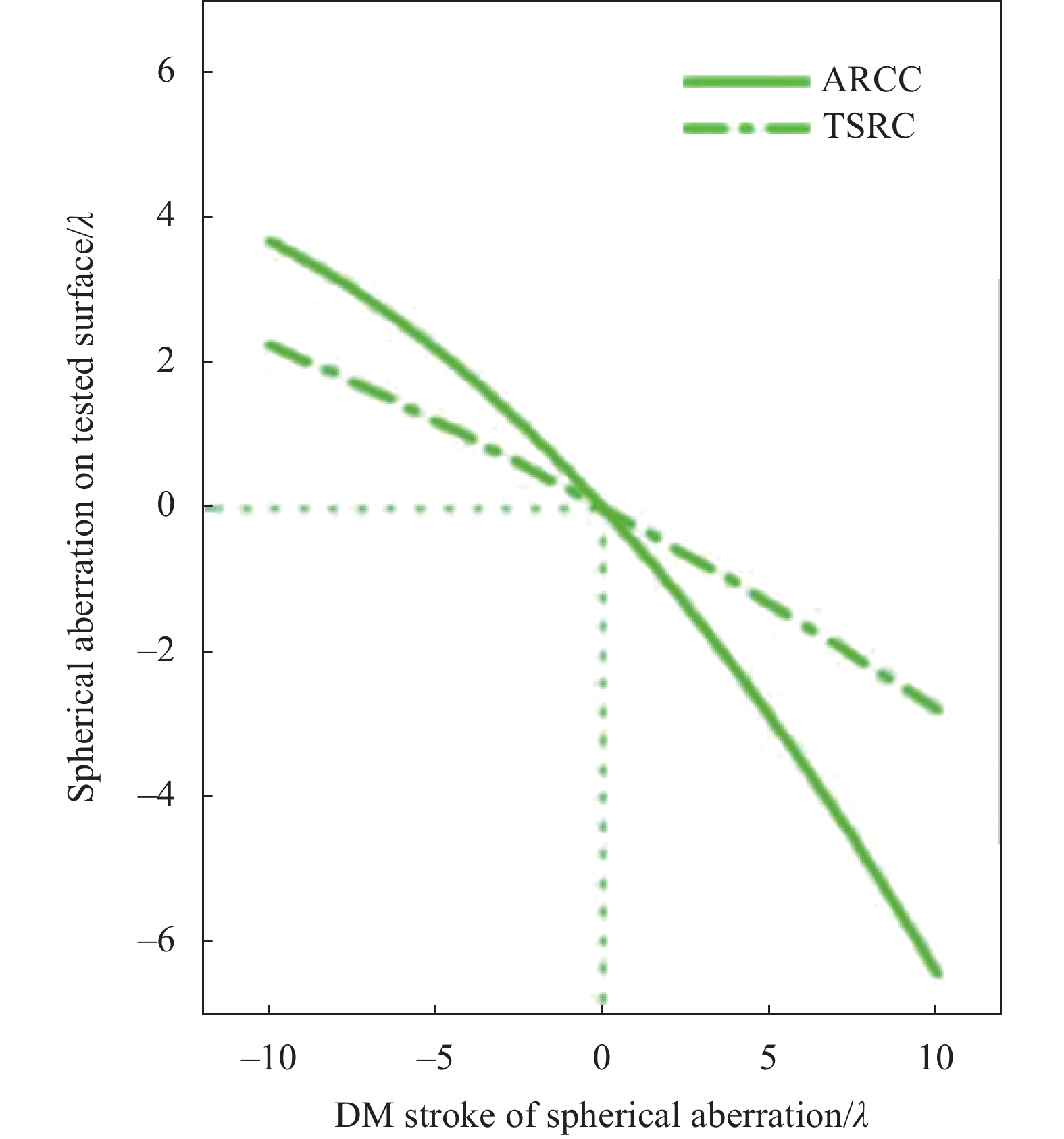
$ {\lambda} $ 以下,可认为被测面面形已和检测波前相匹配,此时将DM表面附加的像差量与被测面上对应像差的大小作为数据点并进行多项式拟合(拟合优度${{{R}}^2} \geqslant 0.999\;9$ ),如图2~4所示,横坐标表示DM面上所施加的像差量,纵坐标表示优化后(近零位条件)被测面上的对应像差量。由于DM为反射元件,其表面施加的正像差会以负像差的形式补偿被测面,反之亦然。图2(a)和图2(b)分别为DM表面附加一定范围的X像散和Y像散时,两种结构所能带给被测面的像散量,可以看出无论DM上为正像散还是负像散,在相同的DM像散形变量下ARCC结构补偿给被测面的像差量显著大于TSRC结构。并且ARCC和TSRC对两种方向的像散均近似为线性补偿,拟合线的斜率$ \kappa $ 可用来反映各自的补偿能力的大小,即DM上$ n{\lambda} $ 的像差能够给被测面带来$\kappa \cdot n\lambda$ 的补偿量,所以利用ARCC和TSRC补偿同种Zernike像差的能力之比$ {\kappa _A}/{\kappa _T} $ 可近似反映两种补偿器的补偿倍数关系,$ {\kappa _A} $ 表示ARCC的补偿能力,$ {\kappa _T} $ 表示TSRC的补偿能力,如表2所示,ARCC补偿X像散的能力是TSRC的2.006倍,补偿Y像散的能力是TSRC的2.007倍,可认为ARCC补偿像散的能力近似为TSRC的2倍。图3(a)和图3(b)分别为DM表面附加一定量的X彗差和Y彗差时,两种结构所能带给被测面的彗差量,同样地,无论DM上为正彗差还是负彗差,在相同的DM彗差形变量下ARCC结构补偿给被测面的彗差量显著大于TSRC。如表2所示,ARCC补偿X彗差和Y彗差的能力分别为TSRC的1.991倍和2.005倍,所以ARCC补偿彗差的能力也近似为TSRC的2倍。图4为DM表面附加球差时,两种结构所能带给被测面像差补偿量的拟合曲线,从图中可以看出ARCC对被测面球差的补偿呈非线性的关系,虽然不能得到ARCC补偿能力大于TSRC的准确倍数,但仍可以看出ARCC对球差的补偿能力要明显优于TSRC。Aberration types Astigmatism X Astigmatism Y Coma X Coma Y Spherical aberration Range [−24, 28] [−33, 33] [−23, 23] [−16, 16] [−10, 10] Table 1. Range of the each low-order aberration on the DM surface in simulation (Unit: λ)
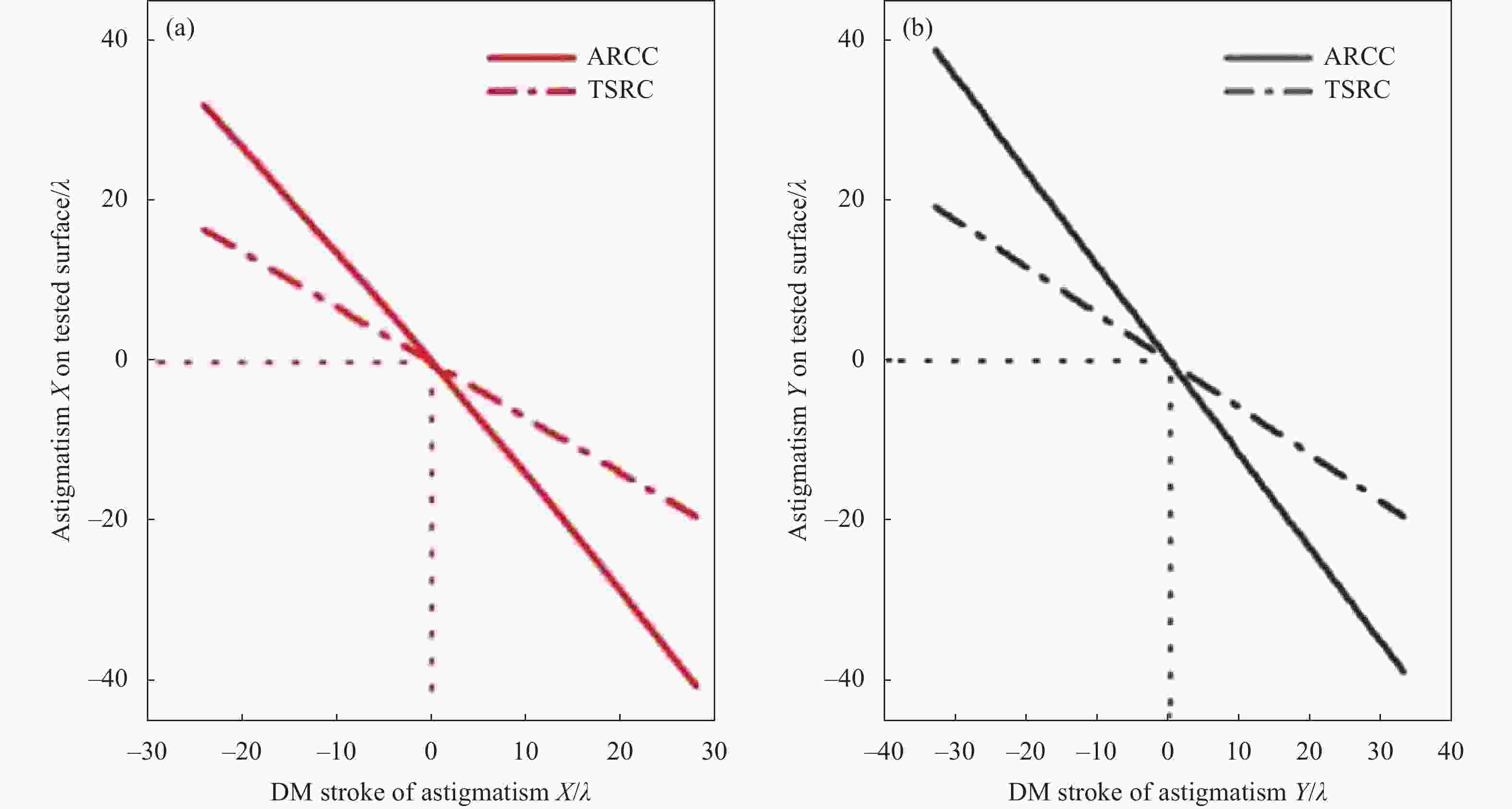
Figure 2. Astigmatism compensation capacity of the TSRC and ARCC. (a) Compensation astigmatism X; (b) Compensation astigmatism Y
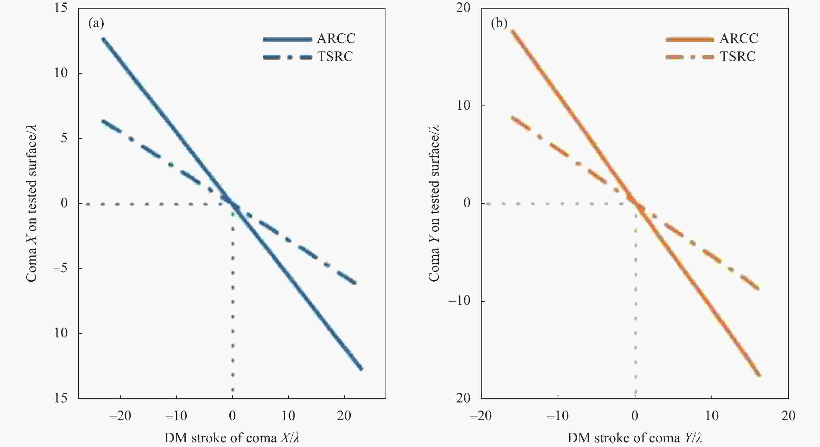
Figure 3. Coma compensation capacity of the TSRC and ARCC. (a) Compensation coma X; (b) Compensation coma Y

Figure 4. Spherical aberration compensation capacity of the TSRC and ARCC
Low-order
aberrationAstigmatism X Astigmatism Y Coma X Coma Y Spherical
aberration$ {\kappa _A}/{\kappa _T} $ 2.006 2.007 1.991 2.005 - Table 2. Ratio of low-order aberration compensation between ARCC and TSRC
-
在系统剩余像差
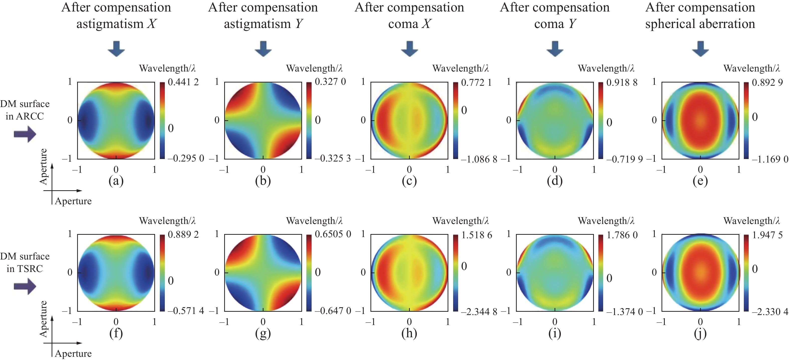
${\text{rms}} \approx {{0\lambda }}$ 时被测面面形近似代表了检测波前形状,两种补偿结构对应被测面上的像差分布除了具有和DM表面相同的像差类型外,还会出现额外像差,即DM表面为单种的低阶像差形变时补偿结构还会向被测面额外补偿其他像差类型,DM上为同一种像差形变时两种补偿器所产生的额外像差类型相同。产生附加像差的原因为仿真中的被测面并不需要用到DM全口径的补偿,因而圆形口径检测光入射至倾斜放置的DM后在其表面呈现椭圆光斑,由于椭圆区域内Zernike各项正交性丢失所以导致Zernike在此区域拟合出现额外像差项:像散主要引入离焦;彗差主要引入倾斜和三叶草像差;球差主要引入离焦、像散和二阶像散。在实际中若被测表面仅需一种低阶像差补偿时(如像散面),不能在两种结构中的DM上简单驱动一种像差,需要DM产生另外的像差形变辅助性地去抵消相应的额外像差。图5所示为优化两种结构中的DM表面形变去补偿被测面上1
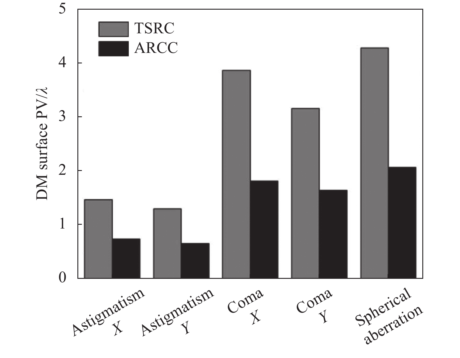
$ {\lambda} $ 单一低阶像差(优化后系统剩余波差$ {\rm{rms}} < 0.05{\lambda} $ ),所得的DM最终表面像差分布情况,图5(a)~(e)表示利用ARCC分别补偿1$ {\lambda} $ 大小的X像散、Y像散、X彗差、Y彗差和球差所引起结构中DM表面的像差分布,图5(f)~(j)表示利用TSRC分别补偿1$ {\lambda} $ 大小的X像散、Y像散、X彗差、Y彗差和球差所引起结构中DM表面的像差分布,可见无论使用ARCC还是TSRC,补偿被测面上单一的像散、彗差或球差均需要DM产生额外像差完成补偿。在此需注意对被测面Y像散的补偿只需要DM产生少量的额外像差(离焦),就能完成补偿。另外,图6所示为两种结构补偿1$ {\lambda} $ 单一低阶像差所需的DM形变量(PV),可以看出,对于补偿同样的低阶像差,ARCC所需的DM形变量要比TSRC中DM形变量小,也就是ARCC中的DM能够用明显少于TSRC中DM的形变量去达到TSRC所能提供的补偿量,这在一定程度上减缓了监测压力,可进一步说明ARCC补偿低阶像差能力要优于TSRC。
Figure 5. DM surface figure in ARCC and TSRC,and the aperture is normalized. (a)-(e) DM surface figure in ARCC that can compensate astigmatism X
, astigmatism Y, coma X, coma Y and spherical aberration with 1 $ \lambda $ respectively; (f)-(j) DM surface figure in TSRC that can compensate astigmatism X, astigmatism Y, coma X, coma Y and spherical aberration with 1$ \lambda $ respectively
Figure 6. DM deformation(PV) required by ARCC and TSRC respectively when compensating for 1
$ \lambda $ single aberration仿真实验对比和分析了两种补偿结构中相同的DM低阶像差形变所能带给被测面像差补偿量的大小,得到ARCC补偿被测面像散和彗差的能力近似大于传统结构TSRC的1倍,补偿球差的能力也要显著大于TSRC,验证了ARCC对低阶像差的补偿优势。同时在被测面面形与检测波前相匹配的条件下进行了ARCC的低阶像差补偿特性分析,由于检测光线与DM表面存在45°的入射角度,ARCC中DM表面的单一低阶像差不会仅补偿圆形被测面一种像差类型,还会引起额外的像差类型补偿,如像散会引起离焦,彗差引起调整型像差和三叶草像差,球差会引起离焦和二阶像散等。论文中的TSRC结构同样如此。反过来,若被测面仅需一种低阶像差补偿时,进而还需DM驱动另外的像差类型辅助性地抵消相应的额外像差。最后进行了两种结构对于补偿同一低阶像差所需DM形变量的反向对比,得出了ARCC中的DM形变量要比TSRC小,即利用小的DM形变产生了大像差,进一步验证了ARCC对低阶像差的补偿优势。
-
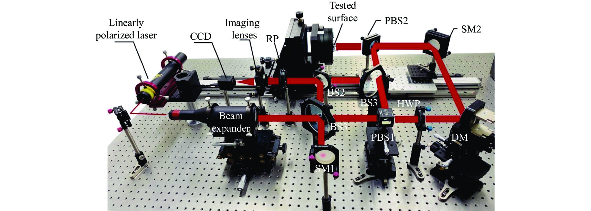
为了验证ARCC在实际中对于低阶像差补偿的优势,故进行了ARCC与传统补偿结构TSRC的像差补偿能力对比实验。实验利用相同的DM形变量分别通过ARCC与TSRC对被测自由曲面进行像差补偿,两种补偿结构的补偿能力大小将会以干涉条纹的疏密程度反映,补偿能力越大则产生的检测干涉条纹越稀疏;反之密集,甚至会出现条纹缺失区域。其中被测面选择4块低阶像差自由曲面(表面反射率
$ r \geqslant 97 $ %),1#自由曲面表面的主要像差类型为像散、2#表面主要分布彗差、3#表面主要分布球差,4#为同时分布像散、彗差和球差的复合像差面,并且每块自由曲面所需的补偿量已知。根据第2节ARCC原理所述,当ARCC中HWP的快轴方向旋转到与p偏振方向平行时,补偿结构成为TSRC型,因此搭建了如图7所示的ARCC实验系统,通过转动HWP的快轴方向来获取ARCC和TSRC在相同的DM形变量下所得的检测干涉图。系统中所用线偏振激光器波长为632.8 nm,DM型号为AlpaoTM 97-25,DM位姿精准调整已在之前的工作中[17, 20]已经完成。4块被测自由曲面1#、2#、3#和4#均为平面基底,因此实验中不需要PNO。由于仅需获取检测干涉图,所以需要将RP的偏振方向调整为与y轴平行(RPy)的状态来获取。

Figure 7. Experiment device
实验中当以平面波直接对1#、2#、3#和4#自由曲面进行补偿时,所获取的检测干涉图皆存在条纹缺失区域,全局无法被CCD分辨,如图8(a)、(d)、(g)和(j)所示。对ARCC中的DM施加一定量像差形变进行补偿后,1#、2#和3#自由曲面的检测干涉图已可被CCD全局解析,4#自由曲面检测干涉图的条纹缺失区域已获得减小,如图8(c)、(f)、(i)和(l)所示。此时旋转HWP的快轴至与p偏振方向平行,ARCC变为TSRC型补偿结构,并且DM表面的形变量保持不变,结果为1#、2#和3#自由曲面的检测干涉图仍存在条纹缺失区域,如图8(b)、(e)和(h)所示,4#自由曲面所得检测干涉图(见图8(k))明显要比在ARCC补偿下所得到的干涉条纹(见图8(l))密集。可见实际中的ARCC同样具有比TSRC更大的补偿能力,证明了ARCC对低阶像差的补偿优势。
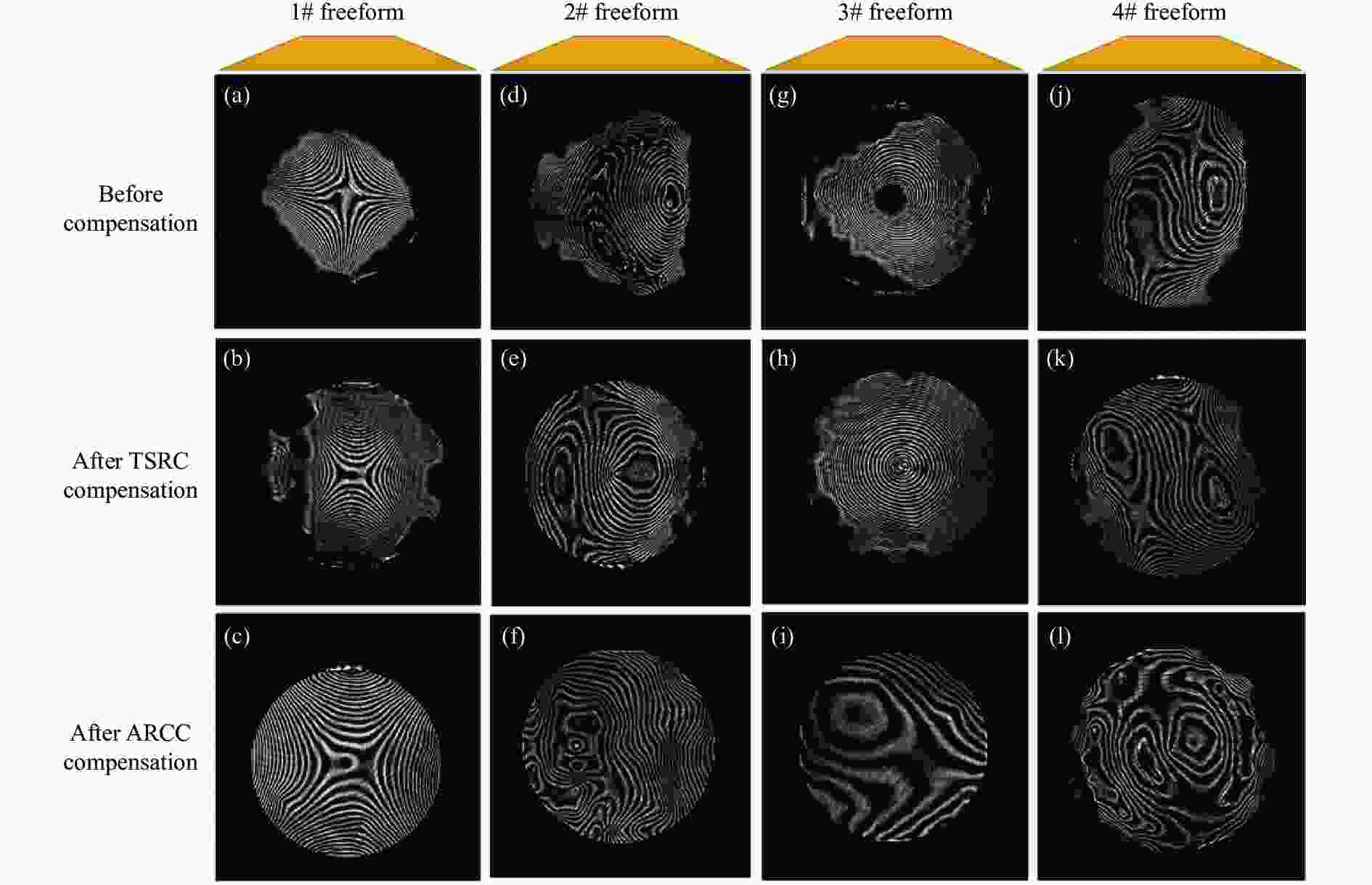
Figure 8. Interferograms of 1#-4# freeform. (a), (d), (g), (j) are the initial interferograms when testing the 1#, 2#, 3# and 4# freeform surface without aberration compensation, respectively; (b), (c) are the interferograms of 1# freeform when compensated by TSRC and ARCC respectively under the same DM stroke; (e), (f) are the interferograms of 2# freeform when compensated by TSRC and ARCC respectively under the same DM stroke; (h), (i) are the interferograms of 3# freeform when compensated by TSRC and ARCC respectively under the same DM stroke; (k), (l) are the interferograms of 4# freeform when compensated by TSRC and ARCC respectively under the same DM stroke
-
针对基于DM的自适应自由曲面干涉仪所存在大像差补偿与DM形变监测范围的矛盾,并结合光学系统中自由曲面多为低阶像差面的现实问题,对自由曲面检测中的自适应循环补偿器ARCC进行了重要的低阶像差补偿研究。仿真与实际实验均进行了ARCC和传统补偿器TSRC对于像散、彗差和球差补偿能力的对比,仿真结果表明ARCC补偿像散和彗差的能力约为TSRC的2倍,补偿球差的能力也显著大于TSRC。以及对于补偿相同的低阶像差,ARCC所需的DM形变量(PV)更小。实际实验中的ARCC能够利用与TSRC相同的DM形变量,使得被测自由曲面(低阶像差面)的干涉条纹全局可被解析或更加稀疏,说明了ARCC提供了更大的像差补偿。因此仿真与实验充分验证了ARCC在低阶像差补偿方面的优势和可行性。同时总结了ARCC对于低阶像差类型补偿的规律,即单一的DM表面低阶Zernike像差类型能够补偿被测面的多种像差类型以及补偿被测面的单一低阶Zernike像差时也需DM表面产生多种像差类型去实现。能够为实际检测提供具有理论依据的指导以及有助于基于更多次波前调制的自适应循环补偿结构设计。
Adaptive cyclic compensation structure used in freeform surface interferometric testing
doi: 10.3788/IRLA20220157
- Received Date: 2022-04-10
- Rev Recd Date: 2022-05-20
- Publish Date: 2022-09-28
Fund Project:
National Natural Science Foundation of China (61705002);Anhui Province Natural Science Foundation of China(1808085 QF198)
-
Key words:
- measurement /
- aberration compensation /
- adaptive cyclic compensation structure /
- adaptive interferometer
Abstract: In order to alleviate the inherent contradiction of existing deformable mirror (DM)-based adaptive freeform surface interferometers, which can not take into account both large departure coverage and DM surface monitoring, therefore, adaptive ring-cavity compensator (ARCC) was proposed, which can generate large departure wavefront using DM deformation multiple times, and it had been preliminarily verified. Considering the practical application of ARCC and the fact that most freeform surfaces in optical systems were low-order aberration surfaces, the low-order aberration compensation characteristics of ARCC were verified and studied. Firstly, the compensation capability of ARCC and TSRC (traditional single round compensator) for astigmatism, coma and spherical aberration was compared by Zemax modeling. It was concluded that the ability of ARCC to compensate astigmatism and coma were about twice that of TSRC, and the ability of ARCC to compensate spherical aberration was also significantly greater than TSRC, which verified the advantage of ARCC in low-order aberration compensation; Secondly, the low-order aberration compensation of ARCC was studied, and it was include that the aberration types on DM in ARCC structure was one-to-many or many-to-one with the aberration types compensated to the tested surface. The results show that in practice, four low-order aberration free-form surfaces are compensated and verified by using ARCC and TSRC respectively. Under the same DM stroke variable, ARCC shows more excellent low-order aberration compensation ability than the TSRC.


 DownLoad: