Volume 52 Issue 1
Jan.  2023
Turn off MathJax
Article Contents

Tong Zhongcheng, Wang Liang, Wu Jun. Simulation research on IR radiation space distribution characteristic of fight plane[J]. Infrared and Laser Engineering, 2023, 52(1): 20220264. doi: 10.3788/IRLA20220264
Citation: Tong Zhongcheng, Wang Liang, Wu Jun. Simulation research on IR radiation space distribution characteristic of fight plane[J]. Infrared and Laser Engineering, 2023, 52(1): 20220264. doi: 10.3788/IRLA20220264

Simulation research on IR radiation space distribution characteristic of fight plane

doi: 10.3788/IRLA20220264
  • Received Date: 2022-04-19
  • Rev Recd Date: 2022-06-17
  • Publish Date: 2023-01-18
  • Considering the IR radiation space distribution research of fight plane is very little, in order to deeply understand IR radiation space distribution characteristics of fight plane in 3-5 μm, the infrared radiation ellipsoid model of tail flare is established, IR radiation characteristics of fight plane in different directions in 3-5 μm are simulated and calculated with the fight plane skin IR radiation model and the tail nozzle IR radiation model, and space distribution curves of IR radiation is given. The calculation shows that the infrared radiation of the aircraft is symmetrical with respect to the wing plane and the longitudinal symmetry plane of the fuselage. There are 4 extremes each in the tail and nose. The maximum value of infrared radiation is 5 177 W when the radiation direction is ($ \pm $150°, $ \pm $32°) in the tail and the maximum value is 3 461 W when the radiation direction is ($ \pm $68°, $ \pm $64°) in the nose. By analyzing the distribution rule of IR radiation of fight plane in the wing plane, the fuselage longitudinal symmetrical plane and the peak value plane, the IR radiation is very low when the radiation direction is positive direction of the plane axis, and the IR radiation grows rapidly when the angle between the radiation direction and the plane axis increases and the radiation direction is not positive direction of the plane axis. The research also shows the direction of peak value of IR radiation is closer to the plane axis in longitudinal symmetrical plane if the angle between the projection of radiation direction in wing plane and the plane axis becomes small. Similarly, the direction of peak value of IR radiation is closer to the plane axis in wing plane if the angle between the projection of radiation direction in longitudinal symmetrical plane and the plane axis becomes small.
  • [1] Chai S J, Tong Z X, Li J X, et al. Infrared radiation characteristics and detection of stealth aeroplane [J]. Fire Control & Command Control, 2014, 39(8): 26-33. (in Chinese)
    [2] Sun W, Wang B. Modeling and simulation of infrared radiation from aerial combat aircraft by fluent[C]//2019 Proceedings of the Conference on Control and its Applications (CT), SIAM, 2019: 25-29.
    [3] Sidonie Lefebvre, Antoine Roblin, Suzanne Varet, et al. A methodological approach for statistical evaluation of aircraft infrared signature [J]. Reliability Engineering & System Safety, 2010, 95(5): 484-493.
    [4] Xu D G, Feng W L, Sang J H. IR characteristics of aircraft aft fuselage skin [J]. Infrared and Laser Engineering, 2013, 42(1): 7-13. (in Chinese)
    [5] Wang X, Gao S L, Jin L, et al. Muiti-band infrared radiation characterization and simulation analysis for aerial target [J]. Acta Photonica Sinica, 2020, 49(5): 0511002. (in Chinese) doi:  10.3788/gzxb20204905.0511002
    [6] Liu Y, Jin Z Q. Simulation of air vehicle motion control models and infrared images [J]. Infrared Technology, 2020, 42(9): 863-872. (in Chinese) doi:  10.3724/SP.J.7102910262
    [7] He P, Wang Y Y, Yue S H. Operating range of the advanced infrared detector for the stealth aircraft [J]. Infrared Technology, 2020, 42(9): 899-904. (in Chinese) doi:  10.3724/SP.J.7102910267
    [8] Kang L Z, Zhao J S, Zhou Q, et al. Research on infrared signature for remotely detection from the nose of aircrafts [J]. Infrared Technology, 2017, 39(4): 365-370. (in Chinese)
    [9] Zhang Y J, Xu Z Y, Li J X. Study on simulation model of aircraft infrared hyperspectral image [J]. Aero Weaponery, 2020, 27(4): 91-96. (in Chinese)
    [10] Tang S W, Liu T Y. Radiation computation of tailpipe based on grid [J]. Electro-Optic Technology Application, 2020, 42(9): 863-872. (in Chinese)
    [11] Wang C Z, Tong Z X, Lu Y L. Study on the airplane's infrared radiation characteristics [J]. Laser & Infrared, 2011, 41(9): 996-1001. (in Chinese)
    [12] Yin X M, Wang L, Zhang X L. Wide band k-distribution model for calculating radiation signal of liquid rocket exhaust plume [J]. Laser & Infrared, 2020, 50(11): 1352-1356. (in Chinese)
    [13] Wang X, Chen H C. Algorithm of infrared signature of aeroplane along the line of sight [J]. Journal of Atmospheric and Environmental Optics, 2008, 3(3): 217-222. (in Chinese)
    [14] Wu X Z, Teng P, Lu Y, et al. Calculation and simulation of infrared radiation about some jet aircraft [J]. Infrared Technology, 2008, 30(12): 727-731. (in Chinese)
    [15] Wang W J, Huang J, Yuan G F, et al. Modeling and application analysis of operating range of air-based infrared system [J]. Optics and Precision Engineering, 2020, 28(6): 1295-1301. (in Chinese) doi:  10.3788/OPE.20202806.1295
    [16] Li Y Z, Sun B, Wang D H. Building model of aeroplane infrared radiant and simulation [J]. Infrared Technology, 2008, 30(5): 252-255. (in Chinese)
    [17] Liu Z Y, Ding F, Ye Q. A practical calculation method of the radiation parameters of particles in rocket plume [J]. Laser & Infrared, 2020, 50(3): 315-318. (in Chinese)
    [18] Zhang H X, Zhang J Q, Yang W, et al. Theoretical calculation of the IR radiation of an aeroplane [J]. Journal of Xidian University, 1997, 24(1): 78-81. (in Chinese)
    [19] Zhu B, Pei Y, Song B F. Estimation method of aircraft infrared radiant intensity based on aerodynamic computation [J]. Fire Control & Command Control, 2011, 36(8): 180-183. (in Chinese)
    [20] Cao X Z, Guo L H. Measurement of the infrared radiation characteristic of the aerobat based on images [J]. Optical Technique, 2007, 33(2): 299-301. (in Chinese)
  • 加载中
通讯作者: 陈斌, bchen63@163.com
  • 1. 

    沈阳化工大学材料科学与工程学院 沈阳 110142

  1. 本站搜索
  2. 百度学术搜索
  3. 万方数据库搜索
  4. CNKI搜索

Figures(6)

Article Metrics

Article views(384) PDF downloads(132) Cited by()

Related
Proportional views

Simulation research on IR radiation space distribution characteristic of fight plane

doi: 10.3788/IRLA20220264
  • Institute of Electronic Countermeasure, National University of Defense Technology, Hefei 230037, China

Abstract: Considering the IR radiation space distribution research of fight plane is very little, in order to deeply understand IR radiation space distribution characteristics of fight plane in 3-5 μm, the infrared radiation ellipsoid model of tail flare is established, IR radiation characteristics of fight plane in different directions in 3-5 μm are simulated and calculated with the fight plane skin IR radiation model and the tail nozzle IR radiation model, and space distribution curves of IR radiation is given. The calculation shows that the infrared radiation of the aircraft is symmetrical with respect to the wing plane and the longitudinal symmetry plane of the fuselage. There are 4 extremes each in the tail and nose. The maximum value of infrared radiation is 5 177 W when the radiation direction is ($ \pm $150°, $ \pm $32°) in the tail and the maximum value is 3 461 W when the radiation direction is ($ \pm $68°, $ \pm $64°) in the nose. By analyzing the distribution rule of IR radiation of fight plane in the wing plane, the fuselage longitudinal symmetrical plane and the peak value plane, the IR radiation is very low when the radiation direction is positive direction of the plane axis, and the IR radiation grows rapidly when the angle between the radiation direction and the plane axis increases and the radiation direction is not positive direction of the plane axis. The research also shows the direction of peak value of IR radiation is closer to the plane axis in longitudinal symmetrical plane if the angle between the projection of radiation direction in wing plane and the plane axis becomes small. Similarly, the direction of peak value of IR radiation is closer to the plane axis in wing plane if the angle between the projection of radiation direction in longitudinal symmetrical plane and the plane axis becomes small.

    • 运用红外探测系统实现对飞机的探测与跟踪成为对空预警探测的发展趋势。目前,国内外对飞机红外辐射的研究较多[1-4],但研究主要集中在飞机在平面内的红外辐射分布,对其空间分布特性鲜有文献报道。天空背景在3~5 um波段红外辐射比较弱,利用飞机3~5 μm波段的红外辐射实现对来袭飞机的逼近告警具有一定的优势,因此,研究飞机在3~5 μm波段的红外辐射空间分布特征,对红外搜索跟踪系统对飞机的识别,以及对飞机红外隐身技术的研究,都具有参考意义。

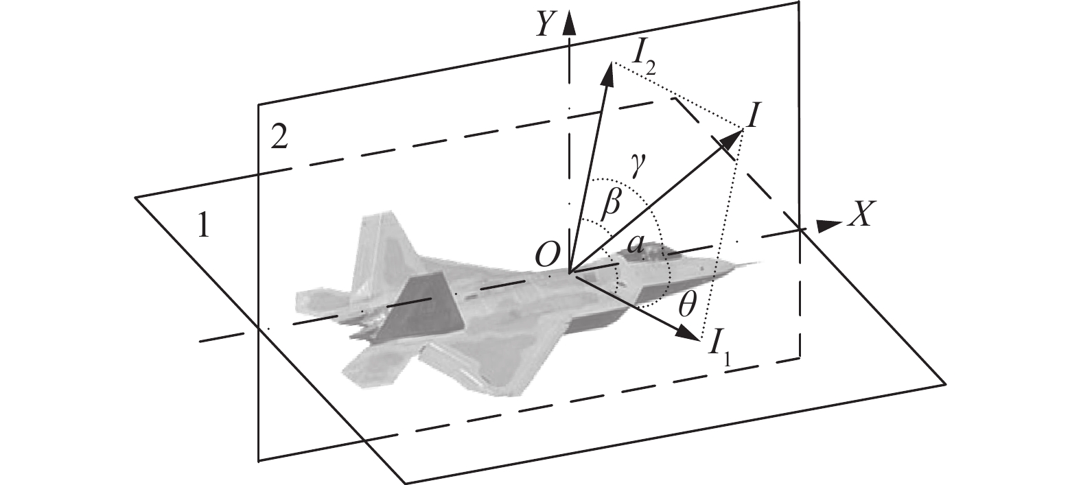
    • 建立如图1所示的机体坐标系计算飞机任意方向上的红外辐射[5]。平面1为飞机机翼平面,平面2为飞机纵向对称平面,平面1与平面2的交线为机轴,也是坐标系的X轴,机头方向为正。辐射方向与机轴的交点O为坐标原点,Y轴在平面2内且垂直于X轴。辐射方向OI在平面1投影OI1X轴夹角为$ \theta $OI在平面2左侧为正,在平面2右侧为负。辐射方向OI在平面2投影OI2X轴夹角为$ \gamma $OI在平面1上方$ \gamma $为正,在平面1下方$ \gamma $为负。

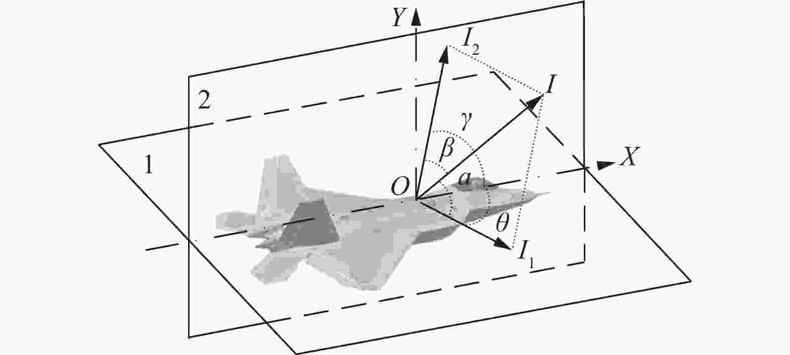
      Figure 1.  Coordinate system of fight plane

      如果能够计算出在飞机机翼平面OI1方向上的红外辐射强度I1和在飞机纵向对称平面OI2方向上的红外辐射强度I2,则OI方向的红外辐射强度I为:

      式中:$ \alpha $OIOI1的夹角;$\; \beta $OIOI2的夹角。$ \alpha $$\; \beta $由下式计算:

      设计算域的中心位于机翼平面OI1和飞机纵向对称平面OI2的交线上,与机头的距离为飞机长度的一半。计算域的长度为机长和尾焰长度2倍的和,宽度为机翼的宽度,高度为垂直尾翼高度的2倍[6]

    • 飞机的红外辐射包括尾焰红外辐射、尾喷管口红外辐射和气动加热的蒙皮红外辐射[7]

    • 尾焰可分为稳定区和混合区,如图2所示[8]。稳定区内温度恒定。稳定区向外直至尾焰边界为混合区,温度逐渐下降。设尾喷口直径为${D_{\rm P}}$,混合区尾焰最宽处直径为${D_{\rm W}}$,稳定区的长为$ {L_1} $,尾喷口到混合区最宽处的长度为$ {L_2} $。将稳定区看为长轴为$ {L_1} $,短轴为${D_{\rm P}}/2$的半个长轴椭圆体,混合区看为长轴为$ {L_2} + {L_0} $,短轴为${D_{\rm W}}/2$的长轴椭圆体。

      Figure 2.  IR radiation model of tail flare

      图2$ {L_0} $为:

    • (1)稳定区温度

      稳定区温度[9-10]为尾焰在尾喷口处的温度。尾焰在尾喷口处的温度与尾喷口的温度有关,其计算公式为:

      式中:$ {T_2} $为尾焰在尾喷口处温度;$ {T_1} $为尾喷口温度;$ {P_2} $为膨胀后的气体压力;$ {P_1} $为尾喷口内的气体压力;$ \gamma_a $为气体的定压热容量和定容热容量之比。

      (2)混合区温度[11-12]

      将混合区划分成若干个离心率相同的长轴椭圆体,如图3中的a1a2···an。设a1a2···an表面积分别为S1S2···Sn,且认为椭圆体表面上温度相同,分别为T1T2···Tna1a2···an都不是完整的长轴椭圆体,需补充完整,如图中点状虚线所示。对于a1a2···an,补全部分不完全一样,但其表面积相差不多。

      Figure 3.  IR radiation model of tail flare mixed region

      设第n个长轴椭圆体表面距喷口的最远距离为$ {l_n} $,则其短轴${{{D}}_n}$和表面积$ {S_n} $为:

      $ S' $为补全部分的表面积,其计算公式为:

      稳定区的表面积$ {A_0} $为:

      a1与稳定区的温差为$ \Delta T $anan−1的温差为$ \Delta {T_n} $,则有:

      式中:$ {T_n} $为第n个长轴椭圆体的表面温度。

    • 稳定区在平面2上沿OI1方向的投影面积为[13]

      n个长轴椭圆体在平面2上沿OI1方向的投影面积An为:

      计算它们在平面1上沿OI2方向的投影面积时用$ \omega $替代$ \theta $,后面类似情形同样处理。

    • 尾喷口可看成灰体,其红外辐射与尾喷口温度${{T}}_{\rm P}$和尾喷口直径有关。尾喷口在平面2上沿OI1方向的投影面积${A_{\rm P}}$[14]

    • 在大气层内蒙皮的温度可用下式计算[15-16]

      式中:${T_{\rm s}}$为蒙皮温度;${T_{\rm a}}$为周围大气的温度;$ V $为飞机的速度。

    • 设机体上方和下方蒙皮面积相等为${A_{\rm u0}}$,机头方向蒙皮面积为${A_{\rm h0}}$,机体侧面蒙皮面积为${A_{\rm s0}}$,则机体上方和下方蒙皮在平面2上的投影面积和机体侧面在平面1上的投影面积为0。

      其中机头蒙皮在平面2上沿OI1方向的投影面积为:

      机体侧面蒙皮在平面2上沿OI1方向的投影面积为:

      机体上下蒙皮在平面1上沿OI2方向的投影面积为:

    • 尾焰、尾喷口和蒙皮都可以认为是具有一定发射率的灰体,知道它们的发射率、辐射温度和有效辐射面积,就可以得到飞机的辐射强度为:

      式中:$ {\varepsilon _n} $${{{A}}_n}$$ {T_n} $分别为尾焰或蒙皮相应计算单元的红外发射率、有效辐射面积和温度;$ M(\lambda ,{T_n}) $为普朗克定律;${\varepsilon _{\rm P}}$为尾喷口的红外发射率;$ \mu $为尾焰对尾喷口红外辐射的衰减系数;$ r $为在辐射方向上尾喷口红外辐射在尾焰中的传输距离[16]

      公式(16)在计算尾喷口红外辐射时考虑了尾焰对它的衰减[17-18]

    • 根据上述模型计算了飞机3~5 μm波段、不同辐射方向上的红外辐射强度,如图4所示。仿真时所用参数主要根据某重型战斗机巡航时的红外图像选取,部分参数根据文献选取。具体为:${D_{\rm P}}$取0.8 m、${D_{\rm W}}$取1.5 m、$ {L_1} $取1.2 m、$ {L_2} $取4 m、${{{T}}_1}$取800 K、$ \gamma $取1.3、P2/P1取0.5、$ V $取300 m/s、${T_{\rm a}}$取250 K、${A_{\rm u0}}$取106 m2${A_{\rm s0}}$取33 m2${A_{\rm h0}}$取8 m2$ \mu $取0.15、蒙皮的发射率取0.5、尾喷口的发射率取0.9、尾焰的发射率取0.85[18-19]

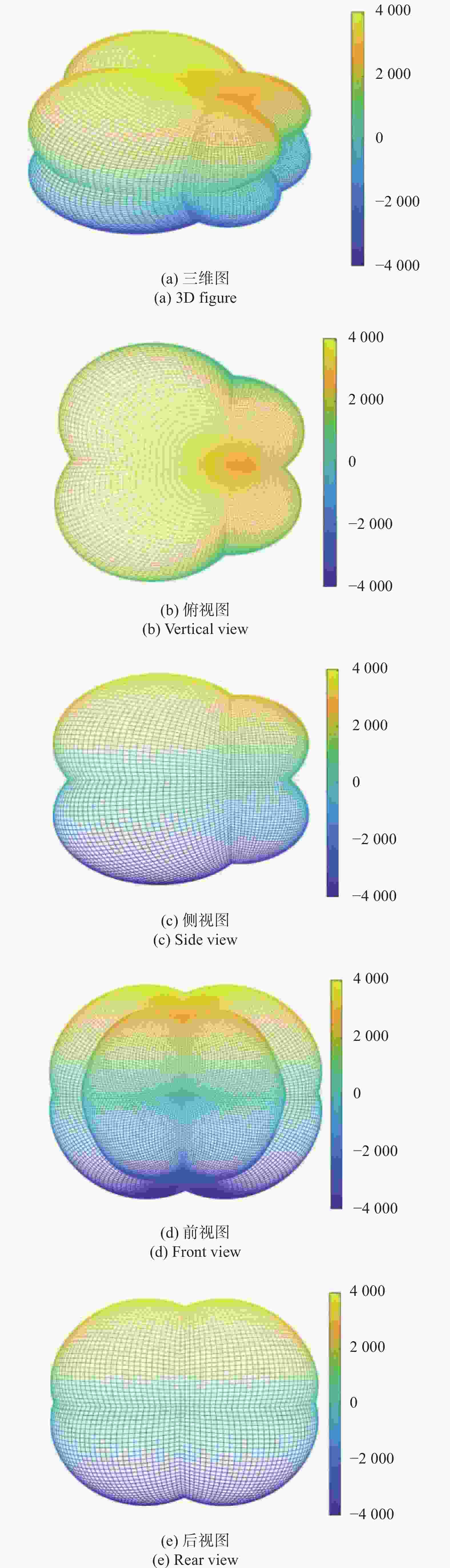
      Figure 4.  IR radiation space distribution of fight plane in 3-5 μm band

    • 图4(a)为飞机3~5 μm波段红外辐射空间分布的三维图,图(b)~(e)分别为三维图的俯视图、侧视图、前视图和后视图。

      图4(a)可知,飞机的红外辐射关于机翼平面和飞机纵向对称平面对称。在机尾和机头各有4个强度相同的极值。根据仿真数据,分析得到机尾极值为5177 W,辐射方向为($ \pm $150o$ \pm $32°)。前头极值为3461 W,辐射方向为($ \pm $68°,$ \pm $64°)。

      图4(b)和(c)可知,飞机的红外辐射在水平面和纵平面的分布都呈鸭梨状,但在纵平面内分布更扁一些,原因是飞机上下表面蒙皮比侧表面蒙皮面积更大。

      图4(d)和(e)可知,在机尾正向和机头正向方向上,飞机的红外辐射比其邻近方向要小,特别是在机头正向上飞机的红外辐射极小。

      从结果来看,仿真得出的飞机红外辐射空间分布曲线与参考文献[1]、[14]一致,均为鸭梨状。但参考文献[14]得出机体红外辐射极值为4500 W,略小于文中极值5177 W,其原因是文中研究机型为某重型飞机,红外辐射的强度与其他机型略有差异。依据参考文献[20]中提供的等效辐射方程,利用某重型战斗机巡航时的红外图像,反推出该战斗机在(145°,−17°)方向上的辐射为4230 W,仿真得到在该方向上的红外辐射为4 823 W,两者相差约为14%,其主要原因是建模时没有考虑不同部位蒙皮之间的遮蔽效应,特别是尾翼蒙皮对机体蒙皮的遮蔽。

    • 根据仿真数据给出了$ \gamma $=0°全方位、$ \gamma $=32°时机尾方向和$ \gamma $=64°时机头方向红外辐射水平面的分布曲线,如图5(a)~(c)所示。其中给出$ \gamma $=32°时机尾方向和$ \gamma $=64°时机头方向红外辐射水平面分布曲线的原因是根据图4在这两个方向上存在极值。

      图5(a)可知,在$ \gamma $=0°时飞机红外辐射水平面分布曲线呈鸭梨状,其极大值为4543 W,此时$ \theta $$ \pm $138°。当$ \theta = {0} $°时,即在机头正面时红外辐射极低,但当$ \theta \ne {0} $°时红外辐射随着$ \theta $的增大急剧增加,其原因是当辐射方向偏离机轴时,飞机侧面蒙皮和尾焰有效辐射面积急剧增加。当$ \theta = {180} $°时,在机尾方面红外辐射有最小值,为3493 W;且当$ \theta $偏离180°时,红外辐射会增加,但增加趋势不如机头方向。

      图5(b)可知,在$ \gamma $=32°时,机尾红外辐射水平分布的极大值出现在$ \theta = \pm {150} $°的方向上。可见随着$ \gamma $的变大,机尾红外辐射极大值的方向越靠近机轴。同样由图5(c)可知,在$ \gamma $=64°时,机头红外辐射水平分布的极大值出现在$ \theta = \pm {68} $°的方向上。而由5(a)可知,当$ \gamma $=0°时,机头红外辐射极值方向为$ \theta = \pm {90} $°,即当$ \gamma $变大时,机头红外辐射极大值出现的方向也越靠近机轴。

      Figure 5.  IR radiation distribution of fight plane in wing plane in 3-5 μm band

    • 飞机红外辐射的纵平面分布如图6所示。图6(a)中曲线以$ \gamma $$ \pm $90°为分界线,右侧曲线对应的$ \theta $=0°,左侧曲线对应的$ \theta $=180°。图6(b)和图6(c)分别为$\theta = {150^ \circ}$$\theta = {68^\circ}$时飞机红外辐射的纵平面分布曲线。

      图6(a)可知飞机红外辐射纵平面分布曲线与其在水平面十分相似,其中$ \gamma $$ \pm $40°时,机尾方向极大值为4528 W。

      图6(b)和图6(c)可知,当$ \theta = {150} $°时,机尾红外辐射纵平面分布的极大值出现在$ \gamma = \pm {32} $°的方向上,当$ \theta = {68} $°时机头红外辐射纵平面分布的极大值出现在$ \gamma = \pm {64} $°的方向上,都呈现出在水平面上$ \theta $的方向越靠近机轴,则在纵平面上红外辐射出现极值的方向也越靠近机轴。

      Figure 6.  IR radiation distribution of fight plane in longitudinal symmetrical plane in 3-5 μm band

    • 文中建立了一种尾焰红外辐射的椭圆体模型,计算得到了飞机3~5 μm波段红外辐射的空间分布曲线。计算结果表明:飞机红外辐射的空间分布关于机翼平面和飞机纵向对称面对称,且在机头和机尾方向各有4个极值。在机头正向红外辐射极低,但辐射方向一旦偏离机轴,红外辐射急剧增加。研究还发现:辐射方向在机翼平面(或机体纵向对称面)上的投影与机轴夹角越小,则在机体纵向对称面(或机翼平面)上红外辐射出现极值的方向越靠近机轴。

Reference (20)

Catalog

    /

    DownLoad:  Full-Size Img  PowerPoint
    Return
    Return