


-
近年来,随着社会经济水平的不断提高,我国交通基础设施的建设迎来了蓬勃的发展,公路建设里程逐年增高,桥梁与隧道的建设也呈现出不断增长的趋势。仅2020年我国就新增公路里程18.56万 km,桥梁3.45万座以及公路隧道3032.7 km。隧道可以克服地形障碍,改善线形,缩短里程,具备其他交通工程不可替代的优势。在城市之间的交流日益紧密,城镇化快速发展的大背景下,隧道被越来越多地应用于缩短城际时空距离,改善城市通勤。截至2020年底,我国已有投入运营的铁路隧道1.963万 km,公路隧道2.199万 km[1]。作为一种地下建筑,隧道的结构与周围的岩体、地下水等介质紧密接触且长期相互作用,随着时间的推移,隧道衬砌会逐渐出现背后空洞,若处置不及时甚至会发展为衬砌掉块与垮塌,严重危害行车安全[2-3]。因此,对隧道进行定期的安全检测是十分必要的。在这个背景下,我国巨量的隧道工程对隧道的检测技术提出了新的挑战[4-5]。
目前,人工使用小锤对隧道衬砌表面进行敲击仍是检测衬砌内部的缺陷最主流的办法,但是这种方法存在高空作业困难、效率低下、缺乏统一的评估标准、以及无法估计劣化状态等问题[6]。为了实现对衬砌内部空洞的快速检测,研究人员对混凝土内部空洞的非接触检测技术展开了研究,Sugimoto等[7-9]利用远距离定向声波发射装置在混凝土表面产生声波,同时使用激光测振仪对激发位置附近的表面振动进行探测,并根据缺陷区域振动信号的特征频率与正常区域不同的特点,实现了对内部空洞的识别。相比于利用远距离定向声波发射装置产生声波,激光致声技术便于集成,易聚焦,分辨率高以及可达性好,激发声波的频带宽,其中高频的声波在缺陷探测中具有极高的灵敏度,目前在金属材料的缺陷检测等方面得到了广泛的应用。
文中将激光致声技术用于混凝土材料,利用激光的烧蚀效应在混凝土表面激发声波,并提出了基于振动能量的缺陷识别方案。在实验室条件下,搭建了激光致声的实验平台,用加速度传感器替代激光测振仪,在内部预制了空洞的混凝土试块表面实现了声波的激发与接收。在混凝土试块表面选取了多个点进行了检测,计算了各个点振动加速度的能量谱,成功实现了对混凝土内部空洞的检测与识别。
-
当材料表面受强激光辐照时,被辐照处因受热膨胀等原因产生应力,应力同时以纵波、横波和表面波等形式的超声波向材料内部或沿表面传播,通过对超声波的反射、散射或衰减进行检测,可以实现对材料内部缺陷的探测[10]。
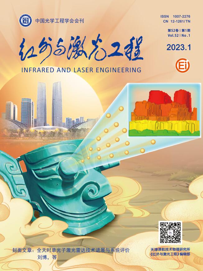
当激光的功率密度较低,热效应引起晶格振动未超过材料的弹性限度时,声波的产生主要依靠热弹效应,如图1(a)所示。由热弹效应产生声波时,热膨胀产生的表面切向应力可以激发出横波、纵波和表面波等多种声波。
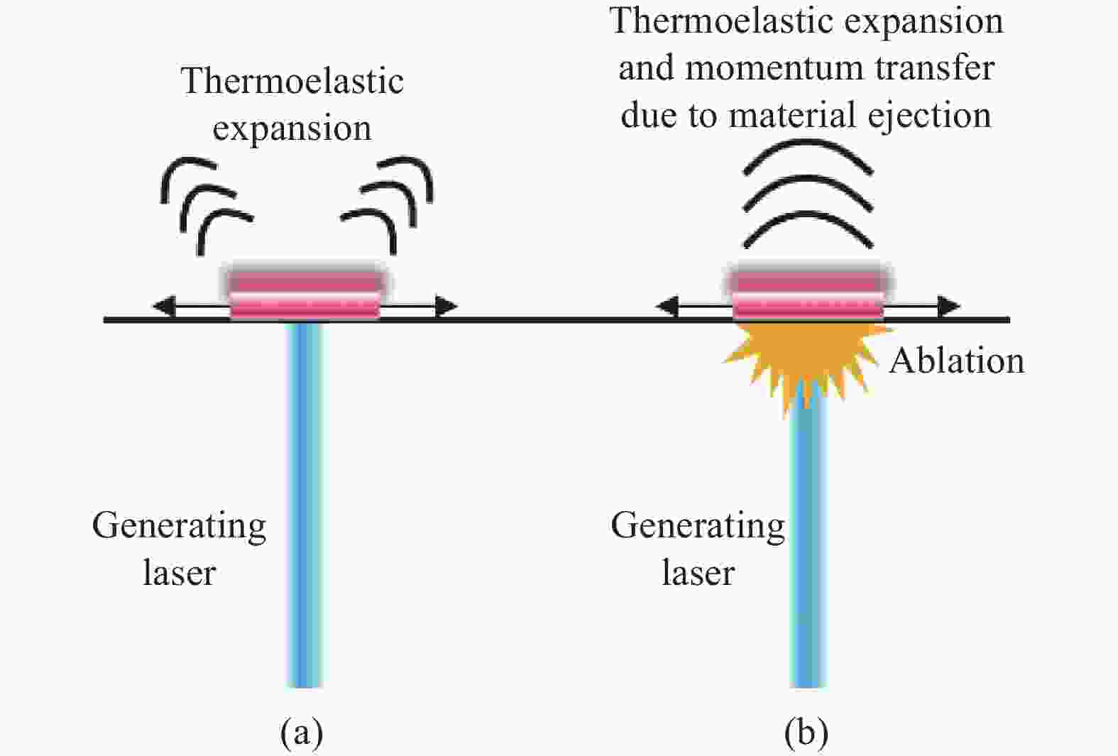
Figure 1. Schematic of laser acoustic. (a) Thermoelastic effect; (b) Ablation effect
当激光的功率密度持续增大,晶格动能随之增大至超过材料的弹性限度时,材料表面被辐照处将会出现局部的熔融,同时伴有等离子体飞出,造成烧蚀现象,在该过程中仍存在热弹效应,但此时声波主要是由烧蚀效应引发,如图1(b)所示。在烧蚀效应产生声波时,飞出的等离子体会在材料上产生一个垂直于表面的反作用力,激发一个垂直向下的应力脉冲,产生较强的横波和纵波[11-12]。这个应力的效果在宏观上与锤击很类似。
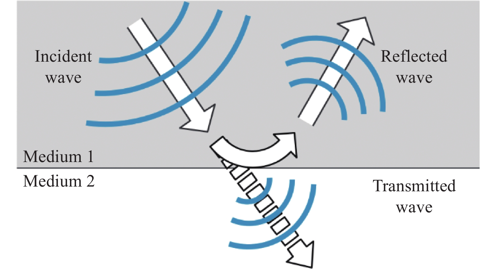
烧蚀效应会在材料表面造成深度在微米量级的损伤,这种程度的损伤并不会影响混凝土的结构安全,也不会在混凝土表面留下可见的表观损伤,在一定意义上是无损的。另一方面,热弹效应所激发声波的能量并不集中在法向,其激发的声波沿法向两侧30°~60°的方向传播,见图1;而烧蚀效应激发的纵波沿法向传播[13],因此烧蚀效应激发可以实现更大深度的探测。综合以上因素,该研究主要利用烧蚀效应激发声波以实现对混凝土内部空洞的探测。
-
当声波从一种介质传播到另一种声阻抗不同的介质中时,会在两种介质的界面处发生一定程度的反射,如图2所示。反射波的振幅与入射角度相关,入射角越小,反射波的振幅越大。在正入射的情况下反射波的振幅有最大值,此时入射波的反射系数F可表示为[14]:
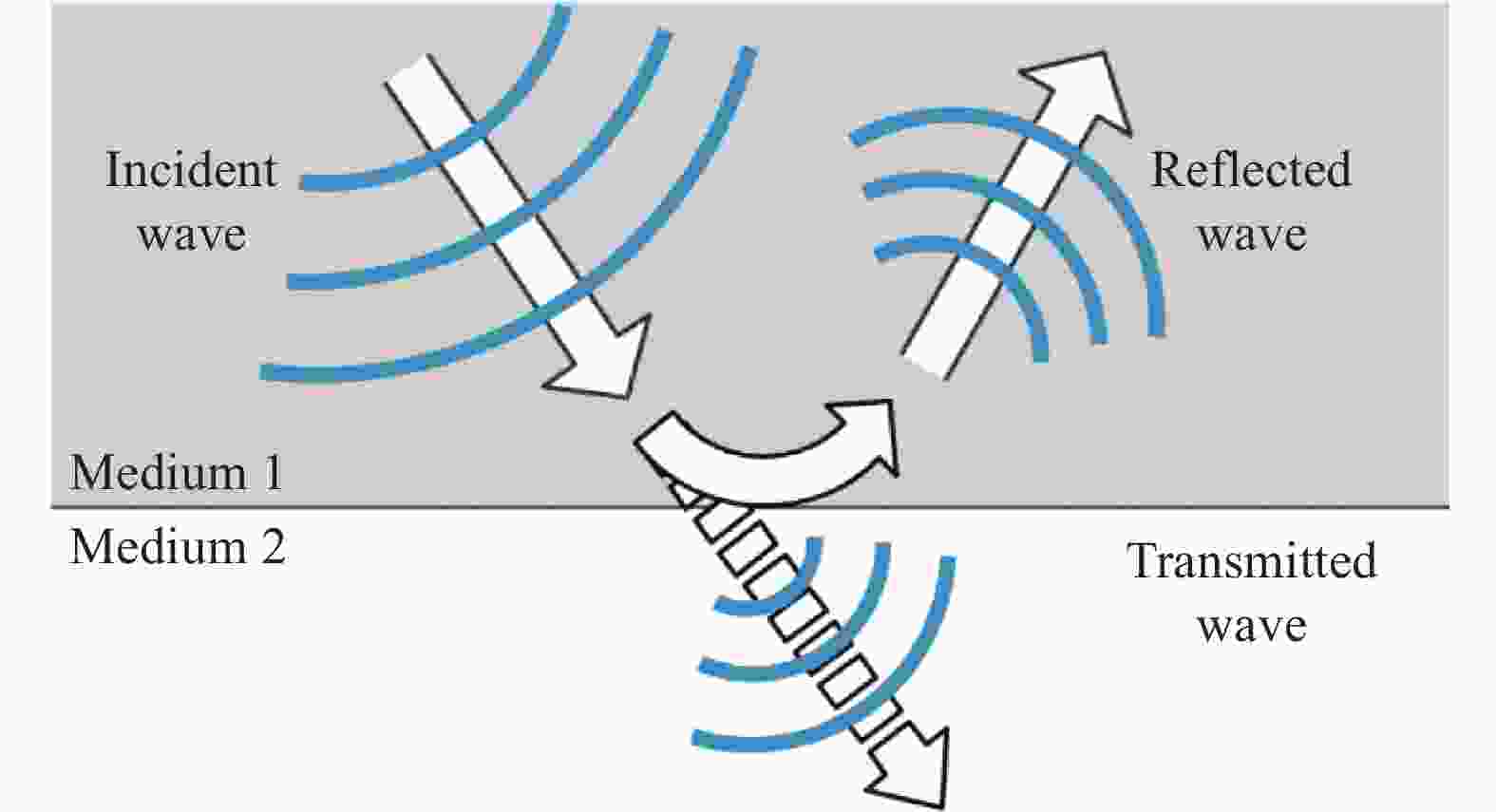
Figure 2. Diagram of sound wave reflection
式中:
${z}_{1}$ 为材料1的声阻抗系数;${z}_{2}$ 为材料2的声阻抗系数。由公式(1)可知,当两种介质的声阻抗系数越接近时声波的反射系数F越小,而当声阻抗系数相差较大时反射系数F的值越大。声阻抗系数$z $ 可由公式(2)计算:式中:
$ \; \rho $ 为材料的密度;c为声波在该种材料中的波速。部分材料的声阻抗系数如表1所示。Material Coefficient of acoustic impedance/kg·m−2·s−1 Air 0.4 Water 0.5×10⁶ Concrete 7×10⁶-12×106 Table 1. Coefficient of acoustic impedance for some materials[14]
由此可见,空气的声阻抗系数接近于0,经公式(1)计算可知声波在混凝土与空气界面处的反射系数约等于1。因此,混凝土内部的空洞会使声波发生强烈的反射。当混凝土内部存在较大面积的脱空时,激光激发的声波会在空洞与混凝土表面之间来回反射并形成纵波共振,引起混凝土表面的位移发生变化。
-
当空洞存在于表面下方的浅层区域时,空洞上方的混凝土的抗弯刚度相对于其他不存在空洞的区域会有所下降。此时纵波共振会引发空洞上方的混凝土的弯曲振动,将空洞上方混凝土近似为一块简支撑的平板,其弯曲振动的一阶固有频率可表示为[15-16]:
式中:h为板的厚度,即空洞深度;a和b分别为矩形板的两个边长;E、v、ρ分别为混凝土的杨氏模量、泊松比以及密度。
-
激光致声混凝土内部空洞检测系统由激光激发和信号采集两个部分组成。声信号由一台输出波长为1064 nm的调Q Nd:YAG激光器激发,其脉冲宽度为8 ns,单脉冲能量0~400 mJ可调,激光脉冲通过两个平面反射镜以及一个焦距为12.5 mm的聚焦透镜实现在混凝土表面的定位以及聚焦。
在距离激光光斑一定距离处使用强力胶水将加速度传感器紧密贴合于混凝土的表面,激光激发的声信号经混凝土内部的空洞反射后回到表面,再由加速度传感器进行接收,接收到的声信号通过数据采集卡采样后在计算机里进行后续的分析与处理,数据采集卡的采样模式为触发模式,采样频率为1 MHz。检测实验装置示意图如图3所示。
Figure 3. Experimental setup diagram for detection of internal cavities in concrete with laser acoustic
-
混凝土试块由在商品混凝土站购买的标准C45混凝土浇筑而成,所购买混凝土的配合比如表2所示。
在三个尺寸为400 mm×400 mm×200 mm的混凝土模具不同深度处固定了尺寸为250 mm×250 mm×10 mm的聚苯乙烯泡沫板以模拟空洞。在模具中浇筑混凝土后,在室温下养护28天,得到了空洞深度分别为30 mm、100 mm以及150 mm的三块混凝土试块,如图4(b)所示。
混凝土试块的相关参数如表3所示,依据表3中的数据,可以通过公式(3)计算得到不同空洞上方混凝土板的一阶固有频率。
Cement/
kg·m−3Flyash/
kg·m−3Fine
aggregate/
kg·m−3Coarse
aggregate/
kg·m−3Water/
kg·m−3321 144 739 1063 153 Table 2. Composition of the concrete
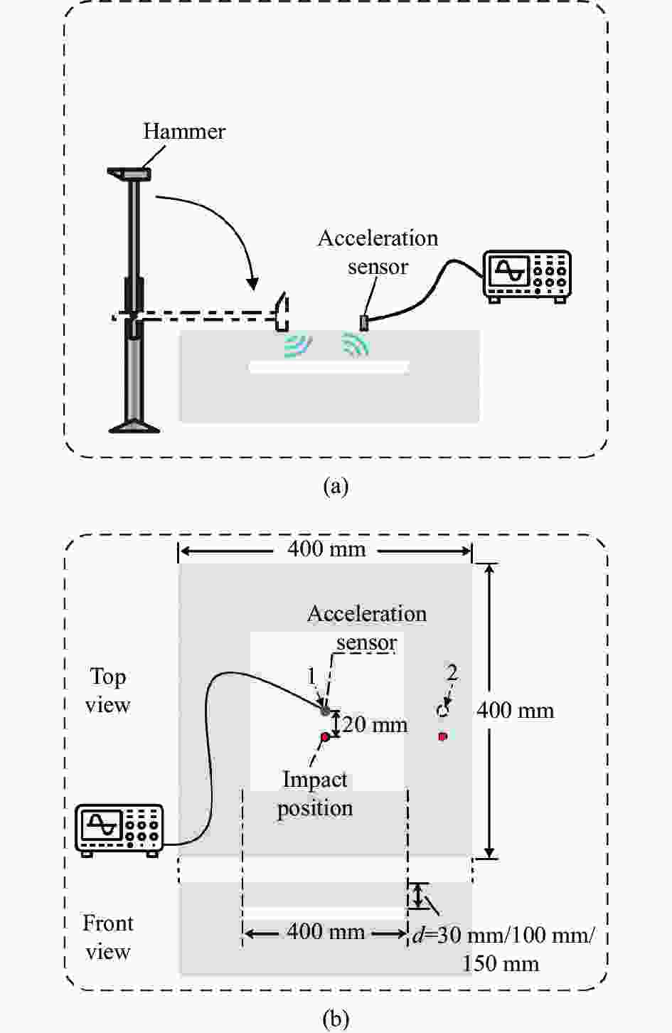
Figure 4. Schematic diagram of experiment device. (a) Schematic diagram of hammer impact experiment; (b) Schematic diagram of concrete
Mass density/kg·m−3 Poisson ratio Young's modulus/Pa 2400 0.2 3.35×10¹⁰ Table 3. Parameter of the concrete
-
小锤敲击作为一种传统的检测方式,在对隧道衬砌缺陷的检查中得到了广泛的应用。为了检验激光激发声波与小锤敲击所产生声波的异同,该研究分别使用小锤与激光在混凝土试块下方密实/空洞区域激发声波,并对返回的声波进行了测量。其中,为了保证每次锤击的力度相同,将小锤与一根固定于桌面的支撑杆铰接,锤击时使小锤与支撑杆呈同一角度并释放,如图4(a)所示。实验中所使用的激光脉冲能量设置为400 mJ,光斑直径为1 mm,此时声波的激发机制为烧蚀激发。
如图4(b)所示,在空洞深度为30 mm的试块表面选取了两个点,其中1号点位于试块中心,在其下方深度为30 mm处存在尺寸为250 mm×250 mm×10 mm的空洞,称为缺陷区域;2号点位于试块边缘,下方密实无空洞,称为正常区域。将加速度传感器分别置于1号点与2号点进行测量,小锤敲击与激光冲击的位置距加速度传感器20 mm,在图中用红点表示。
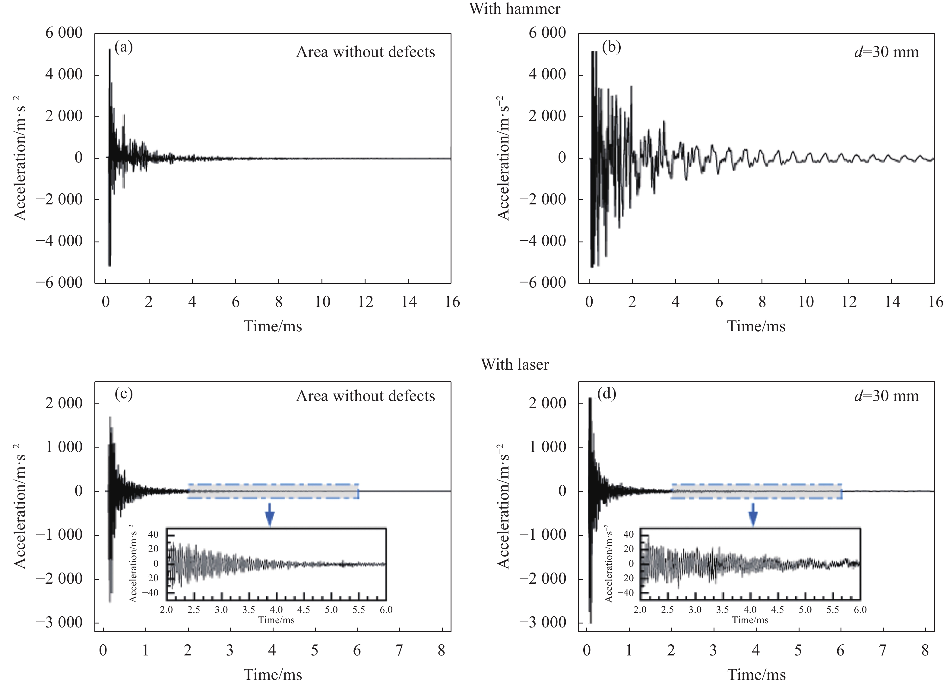
图5(a)、(b)显示了在空洞深度为30 mm时,用小锤分别敲击1号点与2号点的加速度波形图。由图可见,正常区域的加速度信号很快衰减消失,持续时间为6 ms左右。而缺陷区域的加速度信号则表现出持续的衰减振荡的特征,整个衰减信号持续了16 ms以上。图5(c)、(d)分别显示了激光冲击1号点与2号点时的加速度波形图,图中插图为对应波形2~6 ms的时域局部放大图。由图可见,在激光冲击的情况下,正常区域与缺陷区域的加速度信号没有明显的差别,其持续时间在3~4 ms左右。但从图5(c)、(d)的时域局部放大图中可以观察到,缺陷区域的加速度波形表现出周期扰动的特点,而正常区域并未表现该特征。

Figure 5. Acceleration-time graph. (a) Hammer impacts the area without defects; (b) Hammer impacts the area with defects; (c) Laser impacts the area without defects; (d) Laser impacts the area with defects
图6(a)为小锤敲击正常区域的频谱分析图,图6(b)、(c)、(d)分别为小锤敲击空洞深度为30、100、150 mm区域的频谱分析图,图6(a)、(d)中的插图为相应频谱图在0~15 kHz的局部细节放大图。由图可见,特征频率的幅值随空洞深度的增加而降低,当空洞深度为30 mm时,特征频率峰的高度最高达到了200左右,而当不存在空洞时,频率响应的峰值在10以下。另外从频率成分上看,小锤敲击激发的声波的频率主要集中在10 kHz以下,随着空洞深度的增加,频率成分向高频方向移动,这是由于随着空洞深度的增加,弯曲振动的频率也会随之升高。对于混凝土内部不存在空洞的情况,将混凝土试块的厚度代入公式(3),声速取4200 m/s,此时公式(3)的计算结果称为混凝土试块的板厚频率。通过计算,板厚频率应在9 975 Hz左右,正好对应于正常区域的频谱图中幅值最高的峰,其频率为10 864 Hz,如图6(a)所示。当空洞深度为30、100、150 mm时,弯曲振动的特征频率分别为1 342、2 990、3 479 Hz,如图6(b)、(c)、(d)所示。
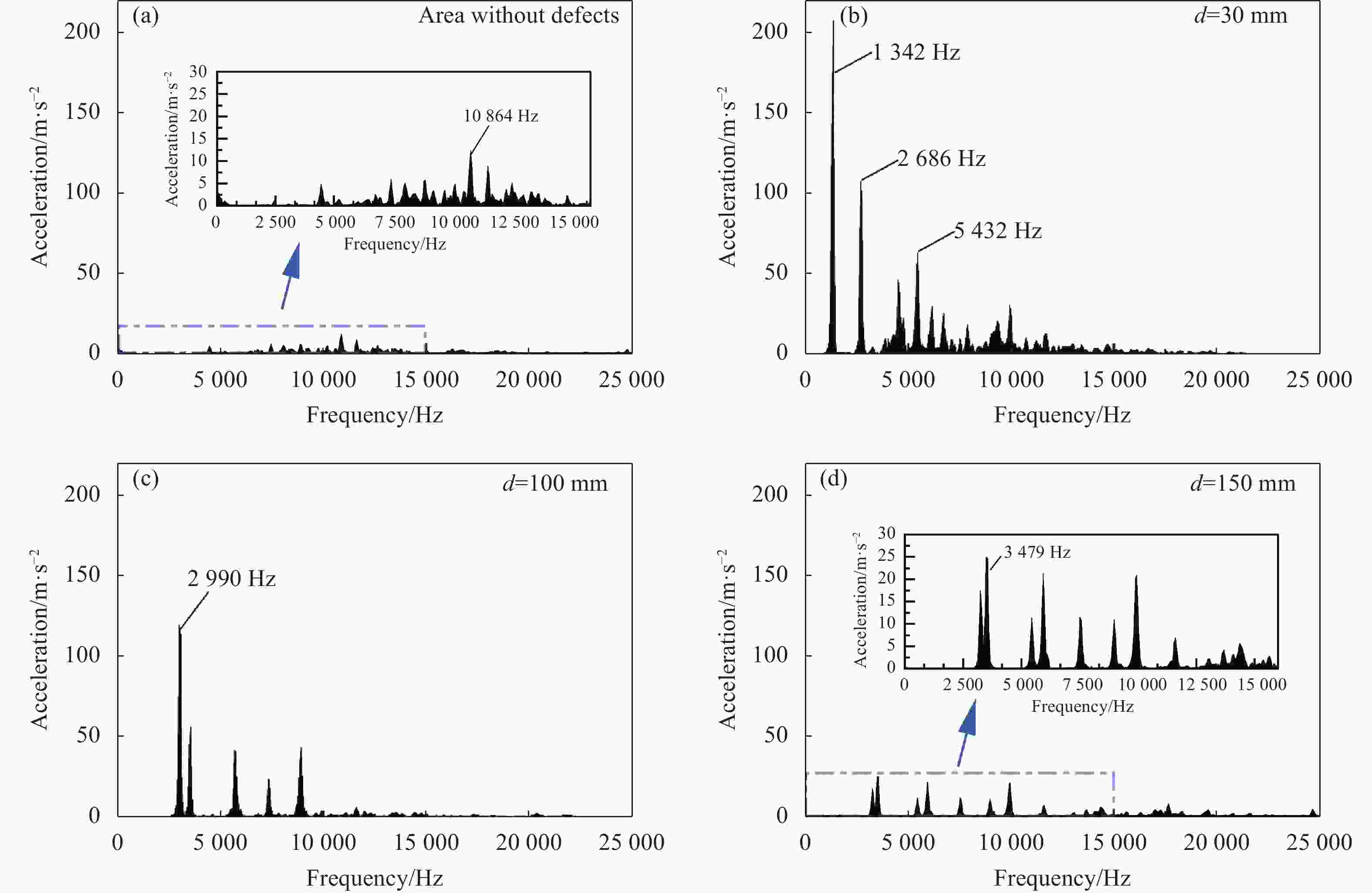
Figure 6. Fourier spectrum of hammer impacting. (a) Area without defects; (b) d=30 mm; (c) d=100 mm; (d) d=150 mm
图7(a)为激光冲击正常区域的频谱分析图,图7(b)、(c)、(d)分别为激光冲击空洞深度为30、100、150 mm区域的频谱分析图,图中插图为相应频谱图在0~15 kHz的局部细节放大图。图7中,无论内部是否存在空洞,激光冲击的频域分析图在24 kHz附近都有一个幅值极大的频率峰存在,而小锤敲击的频域分析图却并找不到与之对应的频率峰,实验中发现该频率峰只在激光烧蚀激发声波时存在,并且是在声波由热弹效应激发转为烧蚀效应激发时出现。由图可以发现,该频率的幅值与空洞的深度不存在明显的相关性,因此推测该频率可能与激光烧蚀激发的表面波有关。
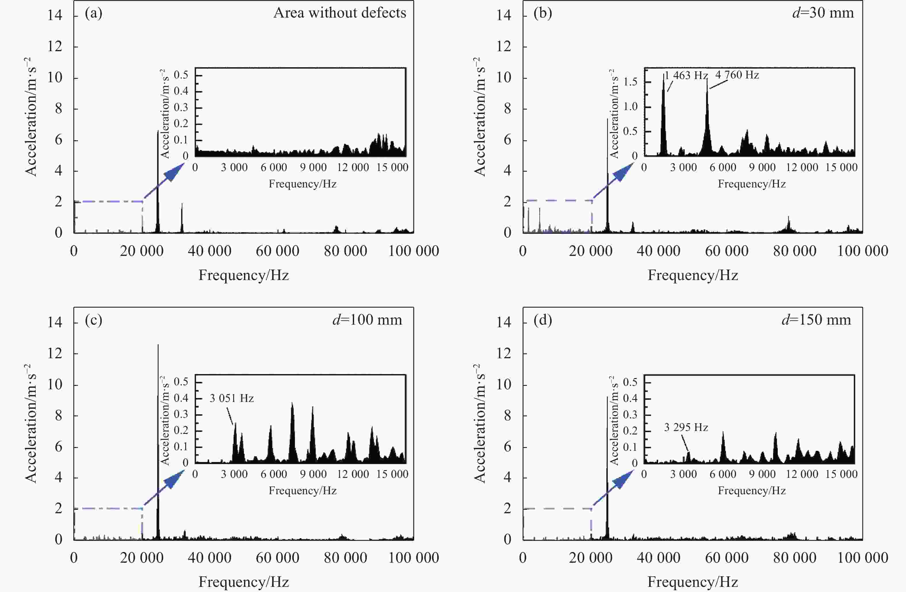
Figure 7. Fourier spectrum of laser impacting. (a) Area without defects; (b) d=30 mm; (c) d=100 mm; (d) d=150 mm

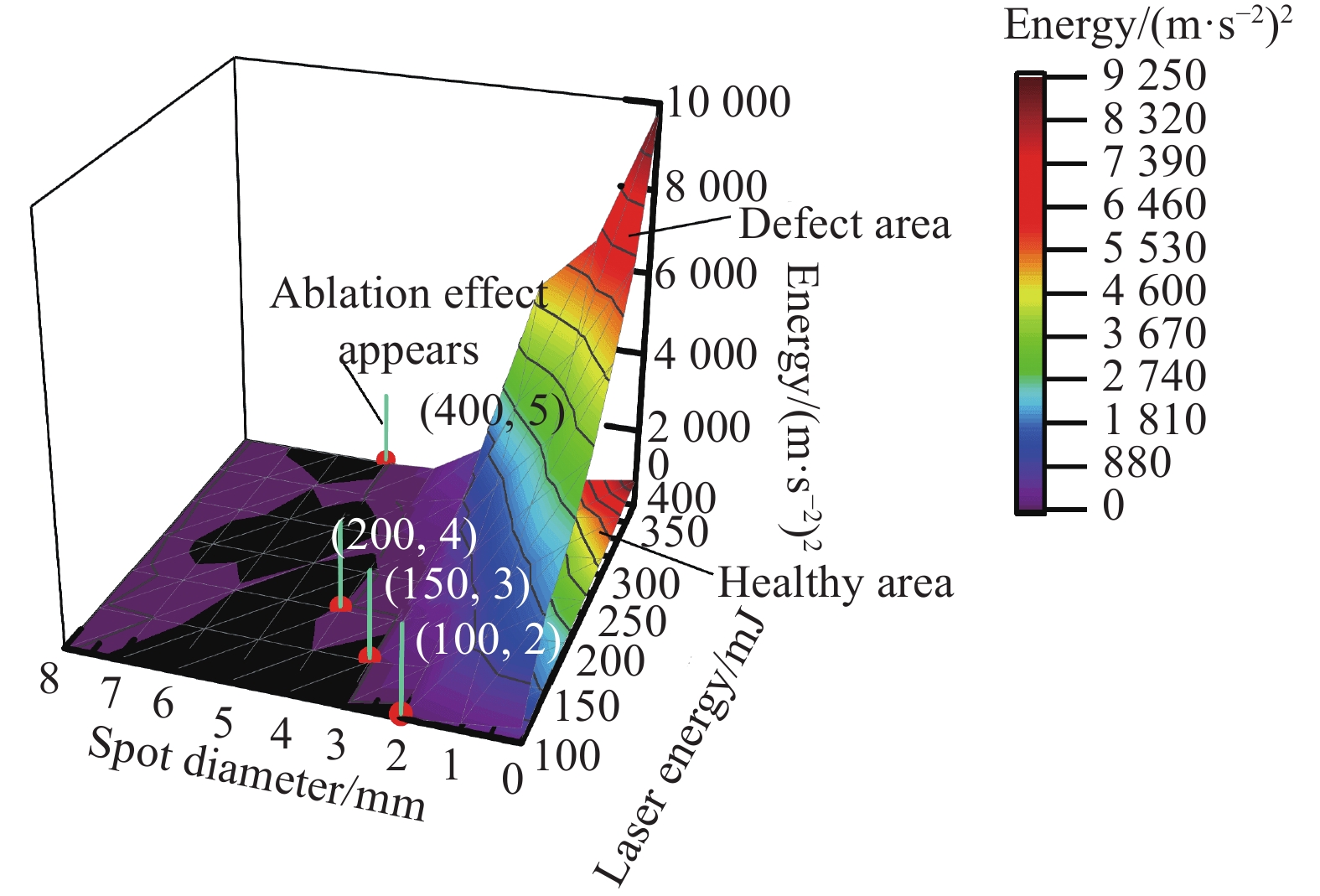
Figure 8. Relationship between vibration energy and laser pulse energy at different spot diameters
与小锤敲击相比,激光冲击所激发声波的频率范围要更广,集中在0~100 kHz这个范围,但是缺陷区域与正常区域的差别仍然主要体现在低频段。由图中可以看到,下方存在空洞时,频谱低频段均存在明显的特征峰,而当下方为正常区域时,由图7(a)可见,低频段并无明显特征峰存在。与小锤敲击相同,在空洞深度为30、100、150 mm时的频域分析图中可以找到对应深度的弯曲振动频率,分别为1342、3051、3295 Hz。
-
通过上述分析可知,弯曲振动的振幅随着空洞深度的增加而不断减小,其在频谱上的特征峰也随之逐渐变弱,最终与其他振型的频率信息混在一起,难以分辨,此时已无法通过特征频率来判断空洞的存在。基于这一点,文中通过对振动能量的计算实现了混凝土内部空洞的识别[7-9]。由于弯曲振动的频率主要集中在低频段,文中用加速度能量谱低频段的积分结果表征振动能量[17],分别计算了正常区域与缺陷区域的振动能量,结果见图8所示。图8展示了在不同光斑直径下,激光脉冲能量在100~400 mJ时缺陷区域与正常区域的振动能量,测点布置仍如图4(b)所示,空洞深度为30 mm,激光光斑距加速度传感器20 mm。图8中,曲面的颜色代表了缺陷区域与正常区域振动能量的差值,图中黑色区域表示缺陷区域与正常区域的振动能量接近,难以区分。当激光光斑大小固定时,调节激光器的脉冲能量,使其从100 mJ增加至400 mJ,随着激光脉冲能量的增加,激光冲击混凝土表面时的声音由开始时的低沉微弱变得尖锐且响亮,最后在激光冲击位置出现等离子体闪光,此时代表激光致声的原理已从热弹效应为主转变为烧蚀效应为主。开始出现烧蚀效应的位置已在图中标出,由图中可以观察到,当烧蚀效应出现后,缺陷区域与正常区域振动能量的差值开始迅速增大。
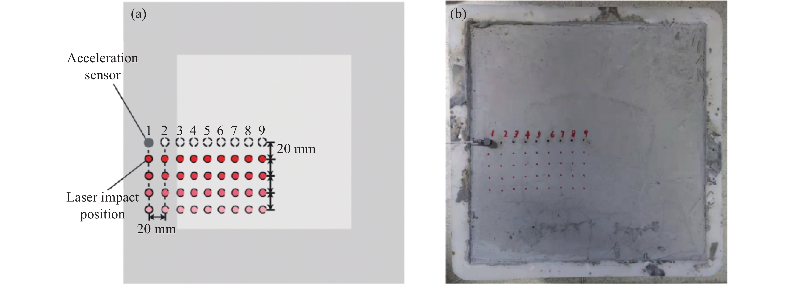
在前述的实验中,振动能量是在将缺陷区域看作一个整体的情况下,作为这个整体的一个属性提出的,但其实在缺陷区域的不同位置处测得的振动能量并不相同,为了探究测点位置对探测效果的影响,在试块表面以20 mm为间隔布置了9个测点,如图9所示。

Figure 9. Layout of measurement points. (a) Schematic diagram; (b) Picture of the experimental layout
其中1号点与2号点位于正常区域,3~9号点位于缺陷区域。测量了激光冲击点与加速度传感器的距离
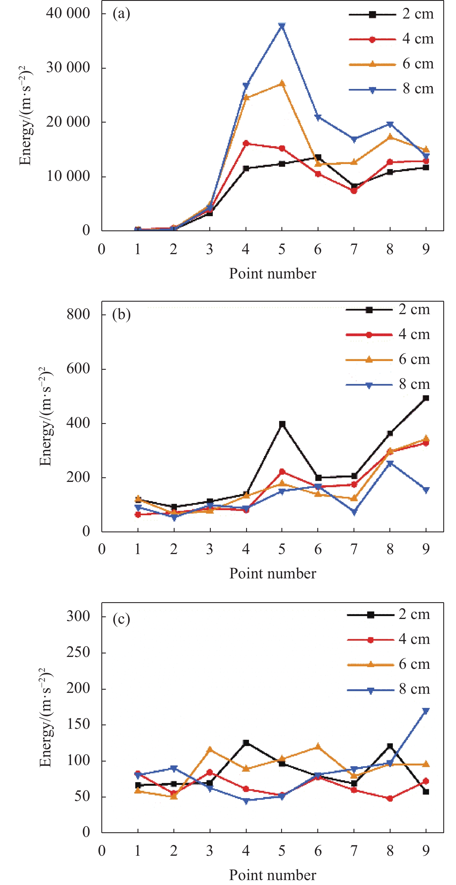
$ {l}_{a} $ 分别为2、4、6 、8 cm时的振动能量,激光脉冲能量为400 mJ,光斑直径为1 mm,每一次测量重复8次取平均,结果如图10所示。其中,图10(a)、(b)、(c)分别为空洞深度为30、100、150 mm时的振动能量图,横坐标代表9个测点,纵坐标代表振动能量的大小。图中,在缺陷深度为30 mm与100 mm时可通过振动能量轻易地区分正常区域与缺陷区域。图10(b)中,1号点由于距离试块边缘较近,受到边沿反射的表面波的影响,振动能量的计算值相比实际会更高,随着空洞深度的增加,空洞上方结构的抗弯刚度逐渐增强,弯曲振动的振幅减小,因此缺陷区域的振动能量也随之降低,而从试块边沿反射回1号点的表面波能量并未降低,因此这种影响会随着空洞深度的增加变得愈加明显。如图10(c)所示,在空洞深度增加至150 mm后,激光冲击距离为2 cm与4 cm时对空洞的识别已存在困难,但在冲击距离为6 cm与8 cm时,仍然能够对空洞进行有效识别。
Figure 10. Echo energy at different distance between impact position and sensor. (a) Depth=30 mm; (b) Depth=100 mm; (c) Depth=150 mm
为了消除试块边缘回波对探测的影响,在同等厚度但没有内置缺陷的混凝土试块中心进行了测量,计算了激光冲击点与加速度传感器距离
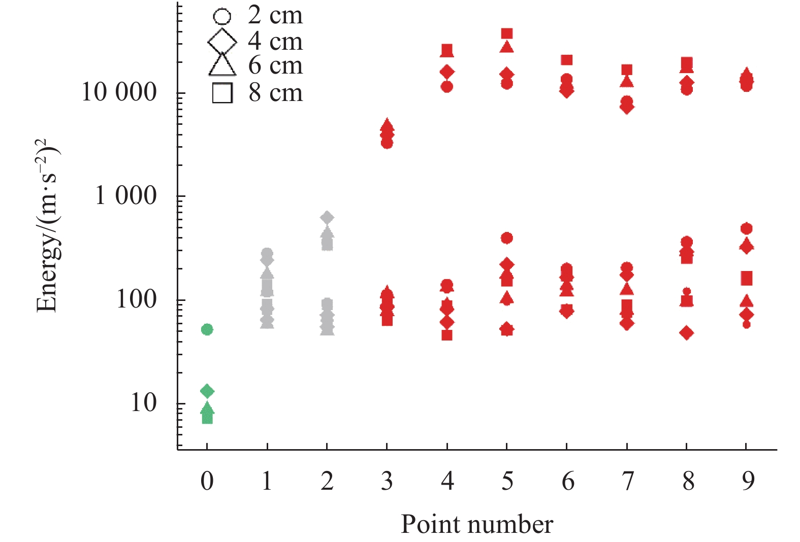
$ {l}_{a} $ 分别为2、4、6、8 cm时正常区域的振动能量值。将正常区域的振动能量值与图9中所测得的振动能量值进行对比,结果如图11所示。
Figure 11. Comparison of vibration energy in the normal area and the defective area
在图11中,横坐标表示测点序号,其中0号点的绿色图案表示正常区域的振动能量,1~9号点表示图9中的9个测点,其中红色图案表示位于缺陷区域内的测点,灰色图标表示缺陷区域外的测点。纵坐标为振动能量,为避免数据过于分散,使用对数坐标作为纵坐标。图中圆形、菱形、三角形以及正方形分别表示激光冲击点与加速度传感器距离
$ {\mathit{l}}_{\mathit{a}} $ 为2、4、6、8 cm的情况。由图11可见,1号与2号测点的振动能量明显高于在无缺陷的试块中所测得的振动能量,甚至大于部分缺陷区域的振动能量。这是由于1号与2号测点位于缺陷区域与试块边缘的中间地带,缺陷区域的声波辐射会使其振动能量大于那些远离缺陷的区域,而试块边缘的声波反射则造成了其振动能量大于缺陷区域的反常现象。排除边界反射的影响,如图中绿标所示,正常区域的振动能量大部分集中在10个单位,比缺陷区域振动能量的最小值低了约一个数量级。观察图中绿标可知,对于远离边界的正常区域,
$ {\mathit{l}}_{\mathit{a}}=2 \; {{\rm{cm}}}{} $ 时测得的振动能量明显高于$ {\mathit{l}}_{\mathit{a}} $ 为4、6、8 cm时的情况,并接近于缺陷区域的振动能量,这是由于当探测点与激发点距离较近时,激光冲击产生的表面波会对探测设备产生较大干扰。实验结果显示,当探测点与激光冲击位置距离在4 cm以上时有较好的探测效果。 -
文中制作了在不同深度处存在空洞的混凝土试块,利用自行搭建的激光致声混凝土内部空洞检测系统对试块进行了测试。基于弯曲振动的特征频率识别与表面振动信号的能量谱积分,文中成功实现了对混凝土内部深度分别为30、100、150 mm空洞的检测与识别,验证了利用激光检测混凝土内部空洞的可行性。在实验过程中,为了探究激光冲击与传统小锤敲击混凝土所激发声波的区别,分别利用激光与小锤在混凝土试块的缺陷区域与正常区域激发声波。测试结果显示,激光激发获得的频率响应范围比小锤敲击更广,对于缺陷区域,激光激发能获得比小锤敲击更多的特征频率峰。文中还探究了不同光斑直径与不同激光脉冲能量组合对混凝土内部空洞检测效果带来的影响。研究发现当激光脉冲能量一定时,脉冲能量密度越大,对内部空洞的识别的效果越好,以烧蚀效应的出现为标志,在烧蚀效应出现后,缺陷区域与正常区域振动能量的差值迅速增大。此外,使激光冲击点与振动探测点保持合适的距离可以有效提高对混凝土内部空洞的探测识别能力,文中的研究显示当探测点与激光冲击位置距离在4 cm以上时有较好的探测效果。
利用激光对混凝土内部空洞实现遥感检测具有广泛的应用前景以及切实的需求,文中验证了利用激光致声技术检测混凝土内部空洞的可行性,为基于激光致声的混凝土内部缺陷的遥感检测积累了宝贵的实验经验。
致 谢 威海光子信息技术产业研究院有限公司对该实验的顺利进行提供了很多便利,在此表示感谢。
Detection of internal cavities in concrete with laser-acoustic method
doi: 10.3788/IRLA20220306
- Received Date: 2022-05-10
- Rev Recd Date: 2022-06-25
- Publish Date: 2023-01-18
Fund Project:
National Natural Science Foundation of China (61675147, 61735010,11674242),National Key Research and Development Program of China (2017YFA0700202,2021YFB2800700).
-
Key words:
- laser technology /
- laser acoustics /
- concrete /
- nondestructive testing
Abstract: The technology of detection of internal cavities in concrete with laser-acoustic method is one kind of remote sensing detection technology for internal cavity of concrete, which has the characteristics of fast detection and non-contact, meeting the needs of identifying the internal cavity of concrete in some cases where it was not convenient to conduct contact detection. In this paper, focusing on the part of acoustic excitation, a laser acoustic concrete internal cavity detection system was built using accelerometers instead of laser vibrometers, and concrete specimens with internal prefabricated cavities were inspected. It was found that the presence of internal concrete voids would change the flexural rigidity of the structure above the voids, and when there was external excitation, the structure above the voids would show the phenomenon of bending vibration, the frequency of which was close to the first-order intrinsic frequency of the vibrating structure. The bending vibration in the defect area can be easily excited by using a high-power density pulsed laser, and when the cavity defect was shallow, the presence or absence of cavity inside can be judged by the characteristic response of the bending vibration in the frequency domain. As the depth of the cavity increased, the flexural rigidity of the structure above the cavity gradually increased, the amplitude of the bending vibration decreased, and the identification of the internal cavity will be difficult to be achieved by the characteristic frequency alone. In this case, the acceleration energy spectrum of the surface vibration signal can be used to characterize the vibration energy and determine whether there were cavities inside the concrete by the level of vibration energy. Based on the above theory, the cavity with a depth of 150 mm inside the concrete was successfully detected, which verified the feasibility of using laser acoustic technology to detect the cavity inside the concrete.


 DownLoad: