


-
300M钢为低合金超高强度钢,因其强度、横向塑性和高断裂韧性能较高,被广泛地应用至飞机起落架制造中[1-2]。飞机起落架服役的工作环境大多复杂多变,当工作于沿海区域或者工作于海洋上空等湿气较重的环境时,空气中潮湿的盐雾气会加速钢材表面的腐蚀。笔者课题组前期已对300M超高强钢在中性盐雾环境中的腐蚀行为及机制进行了研究[3],结果表明300M超高强钢在腐蚀初期以点蚀为主,随着腐蚀反应的进行逐渐发展为后期的均匀腐蚀。由于起落架的性能指标直接关系到飞行的安全,因此提升300M钢表面的耐蚀性能就尤为重要。
在传统的表面改性技术中,常采用渗碳、渗氮、离子注入等手段对钢材表面进行耐蚀处理,但是受限于改性后涂层的厚度,对工艺上的要求就较为苛刻[4]。电镀铬钛是较为常见的耐蚀涂层制备方案[5-6],其方法能够在一定程度上降低析氢反应所导致的氢脆的产生[7],但电镀过程中会产生CN−、Cd2+等大量有毒物质,会对环境造成很大的危害[8]。陈永雄[9]等人采用热喷涂Zn-Al合金涂层方案制备了耐蚀涂层,涂层在高速、高载等复杂工况下会发生脱落,大大降低涂层的使用寿命,因此,采用适当的方法可以降低300M钢等一系列关键部位的运行维护成本。激光熔覆技术作为一种包含物理、化学、材料等多学科领域的新型涂层技术,是表面改性技术的一个分支,它利用高能激光束在基体金属表面辐照,通过迅速熔化、扩展和迅速凝固,在基材表面熔覆一层具有特殊物理、化学或力学性能的涂层,与其他涂层制备技术相比,激光熔覆技术具有加工周期短、热影响较小、且可以保持原熔覆材料的优异性能等优点[10-12],因此可以通过熔覆粉末的方式来提高原材的耐磨性[13]、耐蚀性[14]、高温抗氧化性[15]等。
目前,国内外学者在300M钢的研究多集中在基材表面性能的研究,对于基材的改性和修复上的研究相对较少,而HastelloyC276合金因为优异耐腐蚀性和优异的抗蠕变性在工业生产中的应用已达到较高水平[16],且HastelloyC276本身对氯离子有较强的抵抗性[17],因此,HastelloyC276合金粉末非常适合作为熔覆粉末在300M钢表面制备耐蚀涂层。
-
实验基体材料为300M钢,其化学成分(wt%)如表1所示,将熔覆完成后的试样切割为100 mm×100 mm×12 mm的尺寸,然后使用型号HFB-C50激光仪对试件表面的氧化膜进行处理,并使用丙酮和酒精清洗后干燥放置备用。实验粉末使用Hast公司采用超高转速等离子旋转电极制粉技术(SS-PREP)生产的Hastelloy C276-M粉末,球型粉末具有内部无孔隙、流动性好、保形性好等加工优点,C276合金粉末的化学成分(wt%)见表2,粉末粒径和球度良好,粉末直径约为53~150 µm,实验前将C276粉末置于温度为150 ℃的真空干燥箱中干燥处理并放置备用。
C Si Mn Cr Mo Ni P S V Fe 0.41 1.66 0.64 0.71 0.37 1.90 0.009 0.0013 0.008 Bal. Table 1. Chemical composition of 300M steel (wt%)
C Si Mn Cr Mo W Co Ni 0.0012 0.85 0.53 15.58 16.22 4.15 1.87 Bal. Table 2. Chemical composition of Hastelloy C276 (wt%)
-
实验采用NCLT CW-1K固体Nd:YAG激光器,FANUC R-2000 iB/125L型机器人和同轴送粉器(Ray-cham RC-PGF-D),为方便描述,将不同扫描速度所制备的涂层分别使用编号H1(5 mm/s)、H2(8 mm/s)、H3(11 mm/s)、H4(14 mm/s)表示。涂层制备时,将干燥处理后的C276粉体加入至同轴粉末加料器,激光熔覆过程完全在充满氩气(15 L/min)保护的有机玻璃箱中进行,扫描方式为多道面扫描。
-
在涂层制备后,对试件横截面进行打磨和抛光,电化学腐蚀溶液(HF∶HNO3∶HCl=1∶1∶1)对试件进行浸泡腐蚀,时间限定为300 s,然后通过扫描电镜(S3400N)对涂层组织形貌进行观察和分析。
利用D/mA X-2500型号X射线衍射仪对涂层的物相进行分析;通过HV-1000显微硬度仪采用高压法测定涂层的显微硬度分布,载荷为0.2 kg;载荷停留时间为10 s,硬度点间距为0.05 mm;通过M-2000型环磨损实验机测试并采集涂层摩擦系数,向心载荷为50 N,磨环速为200 r/min,磨损时间为30 min,磨环材料为GCr15,其硬度值为(60±2) HRC,外径为50 mm,厚度为10 mm。电化学采用Princeton Applied Research PARSTAT4000电化学工作站,实验采用三电极工作体系,工作电极(WE)、辅助电极(CE)和参比电极(RE)Ag/AgCl/饱和KCl,腐蚀溶液为2 mol/L的稀盐酸。
-
图1为不同扫描速度下涂层正面和横截面的宏观形貌,由正面形貌直观可见熔覆层表面未出现明显裂纹、孔隙等缺陷,且随着激光扫描速度参数的增加,试件表面平整度越发平整,金属光泽也逐渐加。根据激光束的能量分布,在熔池处具有最高温度,偏离于中心位置的温度会随之减小,由于熔池表面温度不均匀分布,熔池表面存在表面张力差,在熔池流体粘滞力的共同作用下形成Marangoni对流[18-19],毛细力致使熔覆层界面呈弯月状。由横截面形貌可见,当扫描速度为5 mm/s时,单位材料接收热量最大,随着熔覆的进行,熔池热量逐渐累积,温度梯度逐渐变大导致Marangoni对流也随之加强,并且熔覆粉末熔池累积,熔池的厚度达到最大,在重力的作用下熔池内部流体重新形成对流。Marangoni对流的增强导致熔池内流动被加强、扰动加剧,熔池内部流动出现波浪摆动,且流动规则性较差。随着激光扫描速度的增加,熔覆涂层整体厚度下降,涂层内部流动趋于均匀规则。同时随着扫描速度的增加,涂层厚度整体降低,热影响区宽度缩短。

Figure 1. Macroface topography of the coated front and cross section. (a1)-(d1) Front shape;(a2)-(d2) Cross section shape
-
涂层不同扫描速度下的XRD衍射见图2,样品中形成的主要相为Ni-Cr-Co-Mo(PDF-#35-1489)。单相镍基合金的面心立方体具有良好的耐腐蚀特性,为了观察激光扫描速度对衍射峰位置的影响,衍射图样提取2θ=42°~45°,放大如图2所示,当扫描速度为8 mm/s时,衍射峰的位置后移,强度减小;由Bragge方程可得:由于扫描速度较慢,基体与合金材料的温度较高,合金原子固溶于基体中,导致基体晶格畸变,衍射峰位置发生移动;当扫描速度为11 mm/s时,衍射峰的位置前进,强度增加,主要是由于样品中晶体晶格的细化所引起的;当扫描速度为14 mm/s时,衍射峰的位置又向后移,强度减小。整体趋势是衍射峰先向后移强度减小,而后前进强度增加。

Figure 2. XRD diffraction pattern
-
根据涂层不同区域微观组织图可见涂层底部至顶部的组织形态顺序依次表现为平面晶、胞状晶、柱状晶和等轴晶。在涂层结合线处,底部温度梯度G较大,生长速率R较低,因此晶粒形态表现为平面晶。随着反应的进行,结合线位置至涂层顶部,G/R的比值逐步降低,同时也受到其他如激光束冲击、送粉气吹拂等因素的干扰,导致凝固界面转变为非平衡态,因此产生了胞状晶、柱状晶和等轴晶。涂层晶粒结构分布示意图见图3,下文分别对不同扫描速度下(Ⅰ)中心区域和(Ⅱ)多道搭接区域两个部分中的结合处、涂层中部、涂层顶部三个区域进行对比分析。
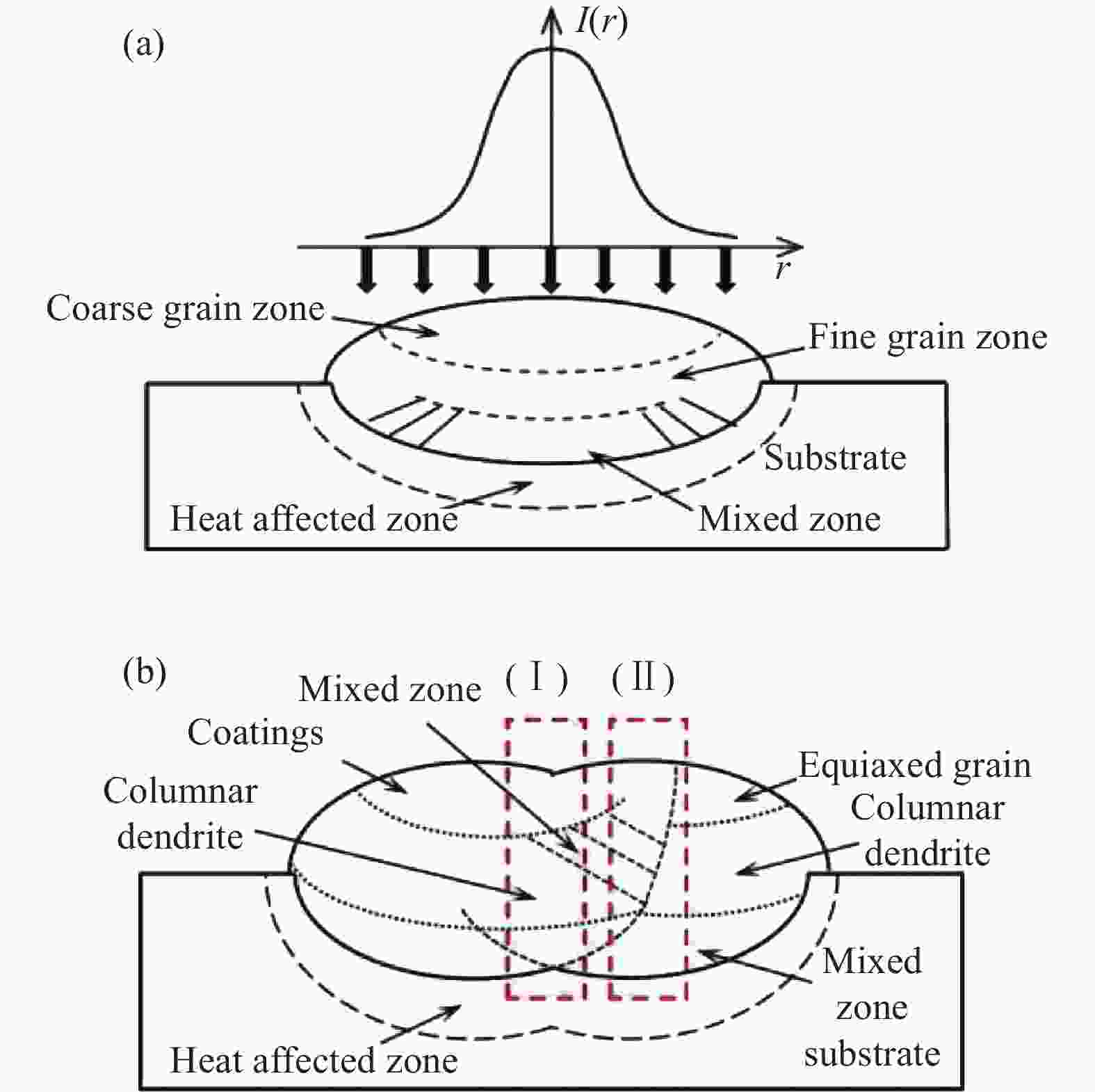
Figure 3. Grain structure distribution of laser cladding single and multi-channel forming. (a) Single channel grain structure distribution; (b) Multi-channel grain structure distribution
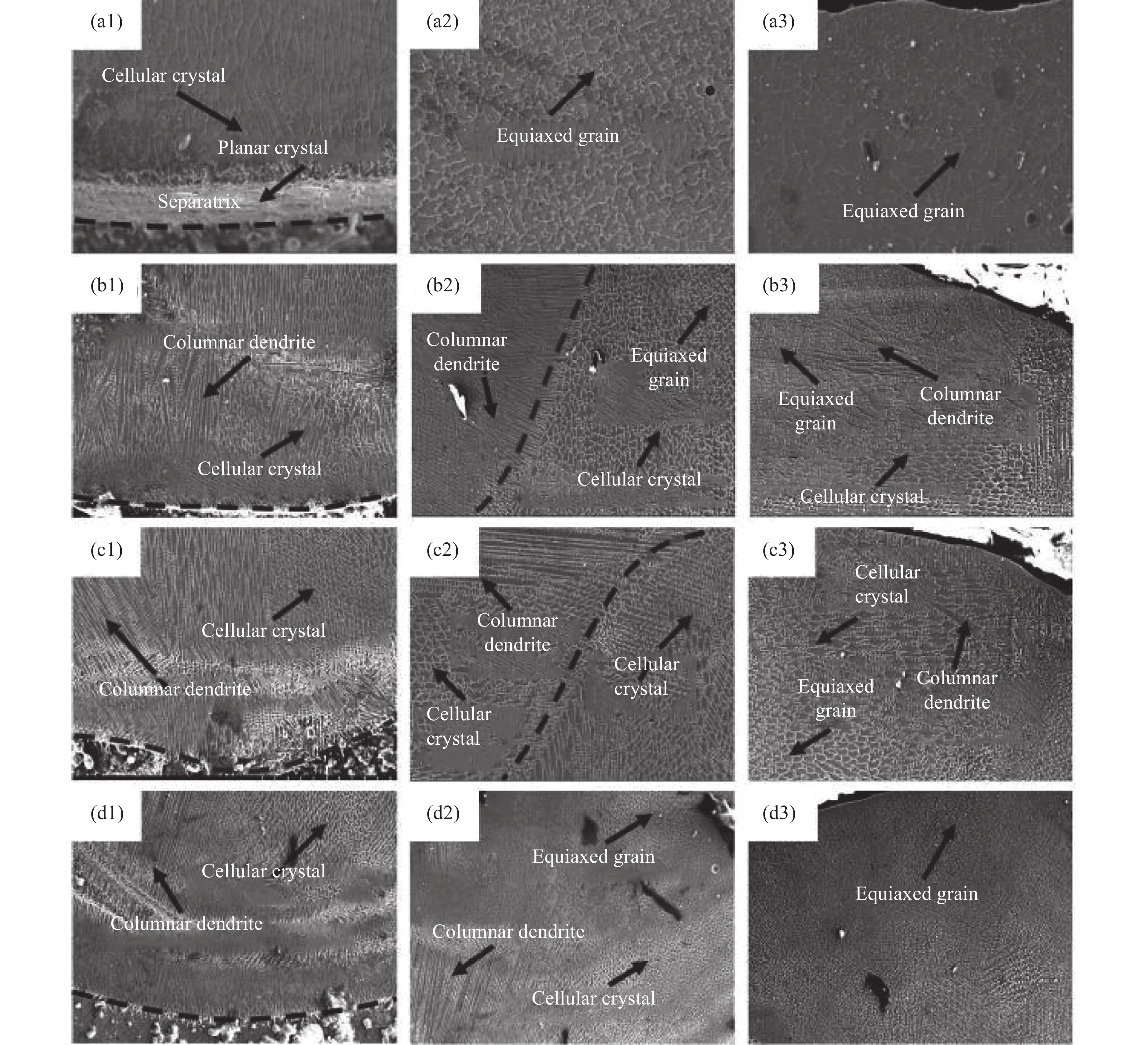
图4所示即示意图的(Ⅰ)区域,H1扫描速度为5 mm/s,涂层底部主要由胞状晶组成且晶粒粗大,随着扫描速度的增加,晶体向上生长为柱状晶,熔覆层底部晶粒排列也逐渐趋于整齐,晶体大小随着扫描速度的增加而变小,晶体生长方向大致垂直于基体,这是由于基体温度较低,散热方向垂直于基体。随着扫描速度的增加,G在一定程度上进一步降低,涂层中的柱状晶在成型过程中逐渐被拉长,H4涂层中出现细小且较长的柱状晶组织。

Figure 4. Microscopic tissue topography of the central area of the C276 coating. (a1)-(d1) Coating and substrate handover zone; (a2)-(d2) Coating in the middle; (a3)-(d3) Coating top
图5所示即示意图(Ⅱ)搭接区域,H1涂层中部为晶粒粗大的等轴晶,H2和H3中心部位出现了晶体的混合区域,由于熔覆搭接率为50%,第二道激光将已成型的晶体组织重新熔化凝固为新的晶体组织。H1和H4涂层在中心部并没有出现明显的混合区,这是由于H1涂层激光扫描速度较慢,熔池内部剧烈的扰动,内部涂层交错无明显规律,没有出现较为明显的混合区,而H4涂层因较高的扫描速度,在重熔的过程中边缘部位受热较小,使材料未充分熔化,并未在中心区域出现混合区域,混合区域出现了向内侧的偏移。如图5(a3)~(d3)所示,涂层的顶部主要为细小的等轴晶组织,同样,H2和H4在顶部的重熔使原本成型的等轴晶重新熔化凝固为胞状晶和柱状晶。H4在所有涂层中获得了更为细小的等轴晶组织。
涂层的形貌和尺寸与温度梯度G和生长速率R有关。G/R决定凝固模式以及凝固后的微观结构[20]。G、R和一次枝晶间距δ可按以下公式计算[21]:

Figure 5. Microtissue topography of the C276 coating lap area. (a1)-(d1) Coating and substrate handover zone; (a2)-(d2) Coating in the middle; (a3)-(d3) Coating top
式中:T为合金粉末的液相温度;T0为基体初始温度;ε为激光吸收系数;P为激光功率;k为材料导热系数;Vs为激光扫描速度;θ为扫描速度与凝固速度的夹角;α为系数。可知当其他条件不变时,随着扫描速度的增加,δ值减小,即晶粒越来越细。
-
图6是涂层边界区与熔覆层搭接区的宏观元素分布,由图6(a)可见涂层与基体结合处的金属元素分布较为均匀,在涂层的搭接区域出现条带状组织,条带组织为富Fe相,涂层与基体的交界处出现少量Fe元素扩散。如图6(b)所示,在条带状组织中Fe元素上升,Ni元素下降,由于300M钢主要成分为Fe元素,激光熔覆过程中基体的元素熔入涂层内部,出现了元素在搭接区域的轻微浮动变化。熔覆层中的合金元素扩散到了300M钢基体中且过渡平稳,形成了良好的冶金结合。

Figure 6. Distribution diagram of EDS element. (a) EDS element distribution at the junction of coating and matrix; (b) Distribution of EDS elements at coating lap
-
图7为不同扫描速度C276涂层中心区域搭接区域的显微硬度分布,测试方向由涂层的顶部延伸至基体。300M钢的平均显微硬度为238.3 HV,涂层硬度分布在293~369 HV之间,熔覆层的整体硬度高于基体。图7(a)为中心区域显微硬度,从图中可以看到:随着扫描速度的增加,涂层的的平均硬度呈现增大的趋势,这是由于随着扫描速度的增加,G×R值越高使晶体的组织更加细化,细化的晶粒可以对涂层的硬度有所提升,这与图6中晶体尺寸的大小相对应。但是,H2和H3涂层在重叠部分的硬度出现局部变小,这是由于在涂层的中部出现了搭接的组织,二次重熔使原本细小的晶粒组织重新熔化凝固为较为粗大的晶枝,另一方面,Cr、W、Mo等合金元素固溶至Ni中,从而达到固溶强化的作用。图7(b)为搭接区域显微硬度,搭接区整体显微硬度随着扫描速度的增加反而减小,这是由于激光重熔使原本在涂层中已成型的细小等轴晶重新熔化凝固为晶粒较为粗大的柱状晶和胞状晶,使涂层的硬度出现了下降的趋势。

Figure 7. Microhardness of the coating center area and lap area. (a) Central zone; (b) Lapping area
-
图8为300M钢基体与涂层摩擦系数曲线图,由图可见,在磨损实验开始时,磨环与试件之间较小的接触面使试件表面所受压力较大,因此摩擦系数曲线迅速增大。随着摩擦磨损实验的进行,试件磨损接触面积逐渐增大,摩擦与试件表面接触逐渐趋于稳定,摩擦系数中心值也趋于稳定。由图可见,涂层的中心摩擦系数随着扫描速度的增加呈变大的趋势,其摩擦系数依次为0.180、0.213、0.205、0.220,与基体的平均摩擦系数0.119相比,熔覆后涂层的摩擦系数均高于300M钢。

Figure 8. Friction coefficient curves of 300M steel and coating
摩擦损耗量由失重法测量,磨损率通过以下公式进行计算:
式中:m为磨损失重量;d为磨环直径;n为转动总圈数。如图9所示,涂层的磨损率为0.174 mg·m−1,基体磨损率为0.0317 mg·m−1。综上可知:基体的摩擦系数和磨损率均小于涂层,熔覆后涂层耐磨性能相比原材降低。

Figure 9. Weight loss and wear rate of 300M steel and coating test piece
-
图10为涂层与基体的电化学分析曲线,图10(a)是极化曲线,其拟合结果见表3,可知基体300M钢的腐蚀电位为−0.351 V,腐蚀电流密度为8.508 E-5 A·cm2,涂层的腐蚀电位与扫描速度之间并非线性增长关系,随着扫描速度的增加,腐蚀电流密度先降低后升高,且H2涂层具有最低的腐蚀电流密度1.536 E-5 A·cm2,表示耐蚀性最强。基体中极化曲线未出现钝化区,而各个扫描速度下涂层中都出现了极为明显的阳极钝化区,这是因为熔覆粉末C276中存在大量铬元素,随着腐蚀反应的进行,试件表面会形成一层致密的Cr2O3膜,减缓涂层的进一步腐蚀,同时钝化区所的对应电流密度位置变化趋势与腐蚀电位随扫描速度变化情况一致,因此,C276涂层比基体具有更好的耐腐蚀性。同时根据图10(b)的Nyquist图,可见H2涂层也具有最大的阻抗弧半径,即具有最优异的耐蚀性能。

Figure 10. 300M steel and coating electrochemical curves. (a) Polarization curves; (b) Nyquist graph
Specimen Icorr/A·cm2 Ecorr/V 300M 8.508 E-5 −0.351 H1 1.674 E-5 −0.247 H2 1.536 E-5 −0.221 H3 3.263 E-5 −0.265 H4 2.995 E-5 −0.272 Table 3. Polarization curve fitting results
-
文中利用激光熔覆技术成功在300M钢表面制备出HastelloyC276耐蚀涂层,通过XRD、电镜扫描、显微硬度、摩擦磨损、电化学性能分析,结果如下:
(1)不同扫描速度下激光熔覆C276合金涂层,通过EDS、SEM、XRD从宏观到微观层面上分析,涂层无明显损伤,与基体有较好的冶金结合,涂层的主要物相为单相面心立方体的Ni-Cr-Co-Mo相。
(2)涂层区域包括单道区域和搭接区域,涂层自基体交界处至涂层顶部产生的组织结构顺序依次为平面晶、胞状晶、柱状晶和等轴晶,搭接区域自涂层中部至顶部产生了较为紧密的等轴晶结构,而两个单道区域之间发生的叠加使原等轴晶重熔成胞状晶和柱状晶结构,并由于扫描速度的增加,在涂层的顶端产生了较为紧密的等轴晶组织。
(3)涂层整体显微硬度明显高于原基材的硬度,但耐磨性能变差,随着扫描速度的增加,中心区域硬度呈现上升趋势而搭接区硬度呈现下降的趋势。当工艺参数扫描功率为800 W,扫描速度8 mm/s时,涂层具有最大硬度,较基体提升了约36.2%。涂层的耐腐蚀性能远高于基体,随着扫描速度的增加,涂层的耐蚀性变化并非线性变化,在扫描速度8 mm/s时涂层具有最优异的耐蚀性能。
Effect of scanning speed on microstructure and properties of 300M steel cladding C276 coating
doi: 10.3788/IRLA20220328
- Received Date: 2022-05-12
- Rev Recd Date: 2022-06-09
- Publish Date: 2023-01-18
-
Key words:
- laser cladding /
- microstructure /
- hardness /
- friction and wear performance /
- corrosion resistance
Abstract: In order to improve the corrosion resistance of the surface of 300M ultra-high strength steel, four sets of coating samples with scanning speeds of 5 mm/s, 8 mm/s, 11 mm/s and 14 mm/s were prepared on the surface of 300M steel by laser cladding technology. The specimen was characterized by optical microscope, scanning electron microscope, X-ray diffractometer, EDS energy dispersive spectrometer, microhardness tester, friction and wear machine and electrochemical workstation instrument, respectively, to characterize the macroscopic morphology, microstructure, phase composition, element distribution, hardness properties, friction and wear properties and corrosion resistance of the coating. The results show that after 300M steel is cladded with C276, the corrosion resistance and hardness of the coating are enhanced, but the wear resistance is worse than that of the original substrate, and the coating morphology is affected by the scanning speed. The greater the scanning speed, the flatness tends to be flatter, and the metallic luster is gradually deepened. At the same time, the phase types of the coating did not change significantly under different parameters, and the main phase was Ni-Cr-Co-Mo. Under the parameter of the scanning speed of 8 mm/s, the coating layer having the highest hardness is about 36.2% higher than that of the matrix, and it also has better corrosion resistance and other mechanical properties.


 DownLoad: