


-
高性能小型空间光学相机应用需求广泛,面对高质量成像要求,在光学系统制造过程中需要对光学元件加工误差和装配误差进行严格的控制,光机结构与热控系统也需要面向光学元件稳定性进行强化设计,以尽可能地减小工作环境对空间相机光学系统造成的误差干扰。一系列策略的实施过程给相机研制带来了较大的投入和消耗,这与高性能小型空间光学相机研制快速化、低成本化的发展趋势已不适应。具备低误差敏感度特征的光学系统可以更好地抵抗由光学元件直接误差或间接误差引起的像质退化,降低实现难度,有效节约成本。因此,开展光学系统低误差敏感度设计(降敏设计),在保证光学系统成像质量的前提下,提升光学系统抵抗误差干扰的能力,使系统鲁棒性增强,具有重要的现实意义。
目前,典型的光学系统误差敏感度优化方法有全局优化法[1-7]、多重结构优化法[8-11]、参数控制法[12-16]以及自由曲面面型优化法等[17-20]。全局优化法是在设计过程中先对光学系统进行像差校正,对完成像质优化的光学系统进行大样本优化和迭代,从大量的设计样本中选取公差鲁棒性较好的系统,进而直接获得低误差敏感度光学系统的方法。全局优化算法可以在一定范围内搜索符合条件的光学系统的最优解,但是需要依靠计算机强大的计算能力,并且需要较长的计算时间。多重结构优化法是在原始光学系统结构的基础上,建立具有包含不同误差类型的多重结构,模拟生产加工和实际应用过程中光学系统可能产生的误差类型与误差量级,对原始光学系统结构与具有误差扰动的多重结构进行同步优化,使所有结构的成像质量仍然在可接受的范围之内,即可说明原始光学系统具备较好抵抗误差干扰的能力。研究人员发现光学系统的一些参数与误差敏感度高度相关,且可以通过数学推导获得这些参数与误差敏感度的规律或明确关系,并据此开展了大量研究,建立了以参数控制为核心的低误差敏感度设计方法。
文中根据低倾斜误差敏感度评价函数[21],提出了一种折反射式光学系统降敏设计方法,对高分辨率小型空间相机光学系统进行了降敏优化设计,所得光学系统成像质量良好,调制传递函数(Modulation Transfer Function, MTF)接近衍射极限。通过对降敏设计后的光学系统施加光学元件位置误差扰动,分析结果显示,对比未采用降敏设计方法获得的光学系统,降敏设计所获得的光学系统其误差敏感度得到了有效降低。
-
倾斜是光学元件位置误差的重要表现形式[22],倾斜误差主要会引起像散等非对称像差,难以通过离焦的方式对像质进行补偿。因此,在光学系统误差敏感度理论研究中,倾斜误差一直被作为重要的研究对象。
误差敏感度评价函数是光学系统降敏设计的核心,为了建立有效的评价函数,首要是探究光学系统在受到倾斜误差扰动的条件下,其内部参数与误差敏感度的明确数学关系,进而在后续降敏设计中对这些参数进行控制,达到降敏的目的。项目组基于几何光线追迹的方法建立了单镜、两镜反射式光学系统模型,以误差所致光程差变化量来表征光学系统对误差的敏感程度,通过推导受到倾斜误差干扰前后光学系统任意一根光线光程差的变化情况得出,光线与镜面交点处切线斜率越大,误差所致光程差变化量越小,意味着误差敏感度更低。
因此,确定了光线与镜面交点处的切线斜率是表征光学系统误差敏感度的关键因素,据此提出了一个以切线斜率为核心的倾斜误差敏感度评价函数。该方法不仅适用于反射式光学系统,同样适用于折射式光学系统。
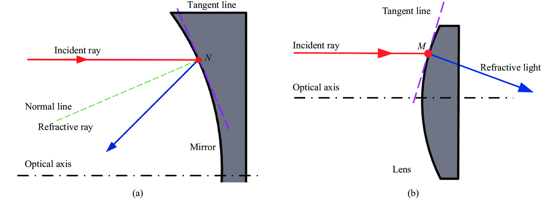
光线在光学元件交点处传播的示意图如图1所示。入射光线经过光学元件时,与光学元件交点为N(或M),在N点(或M点)做光学元件的切线,切线斜率定义为ET。
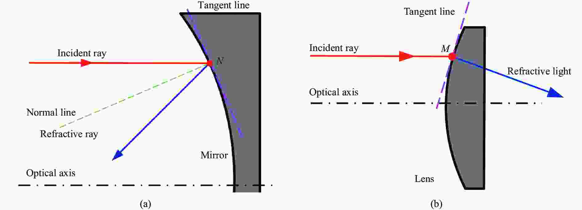
Figure 1. Schematic diagram of light propagation at the intersection of light and optical elements. (a) Mirror; (b) Lens
由前文分析可知,光线与镜面交点处切线斜率ET与光学系统倾斜误差敏感度成反比,因此在降敏设计中ET数值越大越好,但ET作为正切函数不能获得最大值,导致无法设定一个合适的阈值,且从优化函数角度分析,优化过程通常是获得优化函数的最小值。为了便于设置误差敏感度阈值,定义ET倒数的绝对值E=|1/ET|,构建误差敏感度评价函数。
针对单一视场,定义光学系统的所有光学表面误差敏感度评价函数为ES:
光学系统中全部视场的综合误差敏感度ES,F:
式中:i为光学系统的每个光学表面编号,共n个面;k为光学系统的视场编号,共m个视场。
-
根据前文分析,针对折反射式光学系统建立以倾斜敏感度评价函数ES,F为核心的光学系统降敏设计方法,其主要思想是通过优化设计,使光学系统ES,F数值达到目标阈值,获得误差敏感度低的光学系统。设计方法主要分为以下三个步骤:
(1)根据设计指标计算初始光学系统初始结构。
(2)视场拓展与像质优化。若满足像质要求,则继续步骤(3)进行降敏优化设计,若不满足像质要求,则根据需求通过增加光学元件数量、光学元件非球面化等方式继续进行像质优化。
(3)误差敏感度优化,若满足误差敏感度要求则输出设计结果,若不满足要求则对光学系统进行误差敏感度优化。
输出同时满足像质要求和误差敏感度要求的设计结果。
光学系统误差敏感度优化方法流程如图2所示。其中,步骤(3)为光学系统误差敏感度的评价和优化部分,是针对完成像质优化的系统设计的,共分为五个子步骤:
1)误差敏感度判断阈值EV赋值。对于首次设计的光学系统,可以通过误差敏感度函数应用积累给定判断阈值EV,也可以通过批量生成该指标下的光学系统,统计应用一般光学设计软件优化设计方法得到的误差敏感度范围,进而给出判断阈值EV。
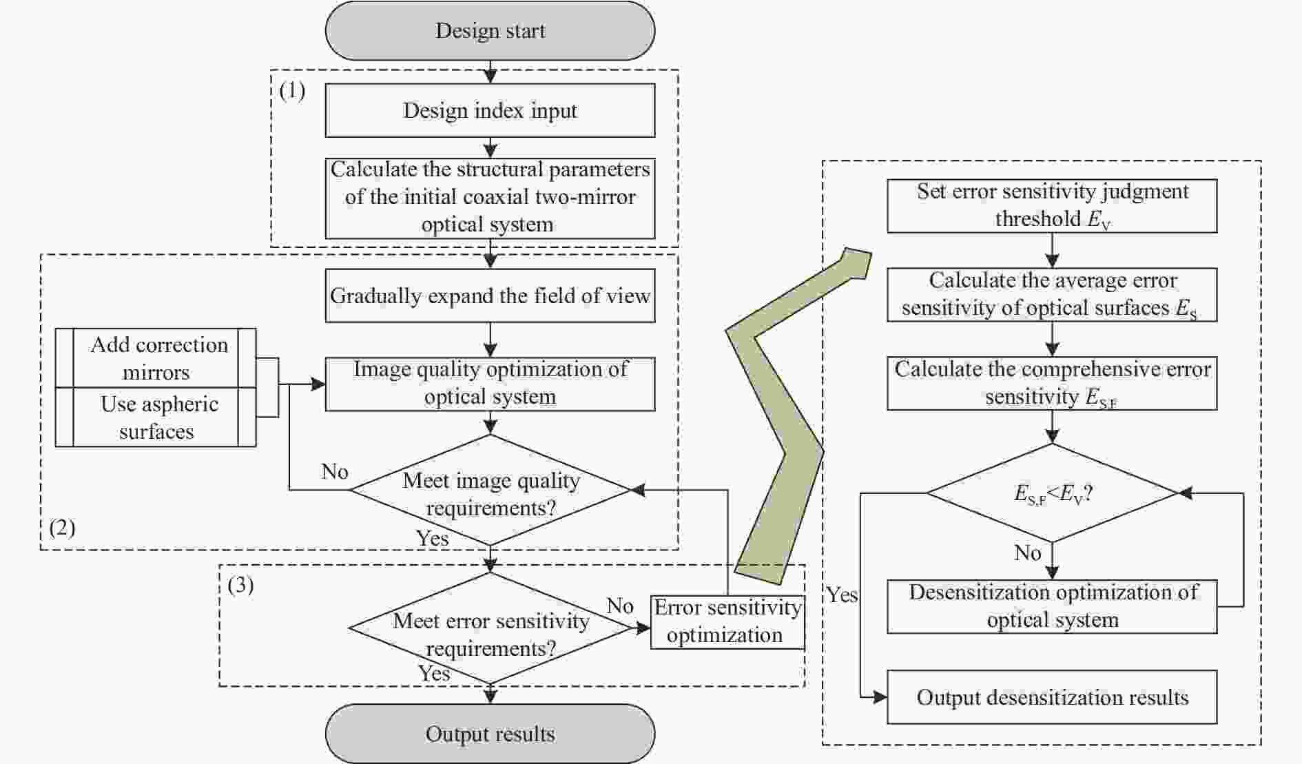
Figure 2. Flow chart of the optimization method for error sensitivity of the optical system
2)根据光学系统参数,计算光学系统中单一视场的面平均误差敏感度ES,根据需要设定视场数量,并计算面和视场的综合误差敏感度ES,F。
3)对光学系统进行误差敏感度评价,若满足误差敏感度要求,则跳过误差敏感度优化子步骤4),若不满足则继续子步骤4)。
4)对系统进行误差敏感度优化,误差敏感度优化过程以ES,F为评价函数,不断降低系统的误差敏感度直至满足要求。误差敏感度优化完成的系统返回子步骤3)。
5)输出结果。子步骤流程图如图2右侧虚线框所示。
-
基于所提出的低误差敏感度设计方法,对一台小型高分辨率空间相机的光学系统进行设计。相机具有质量轻、体积小、经济性强的条件约束,因此在相机研制中,希望在保证高分辨率成像性能的前提下,尽可能地采用简单的光机结构配合一般精度的集成装调工艺进行产品的快速生产。相机光学系统指标如表1所示。
Optical system index Requirement Focal length/mm 500 F number 5 Wavelength/nm 450-750 Field of view/(°) 2ω=4 Total length/mm <180 Back working distance/mm >15 Table 1. Optical system index requirements
-
根据光学系统指标要求,选择同轴两镜折反射式光学系统,按照1.2节提出的低误差敏感度光学系统设计方法进行设计。
-
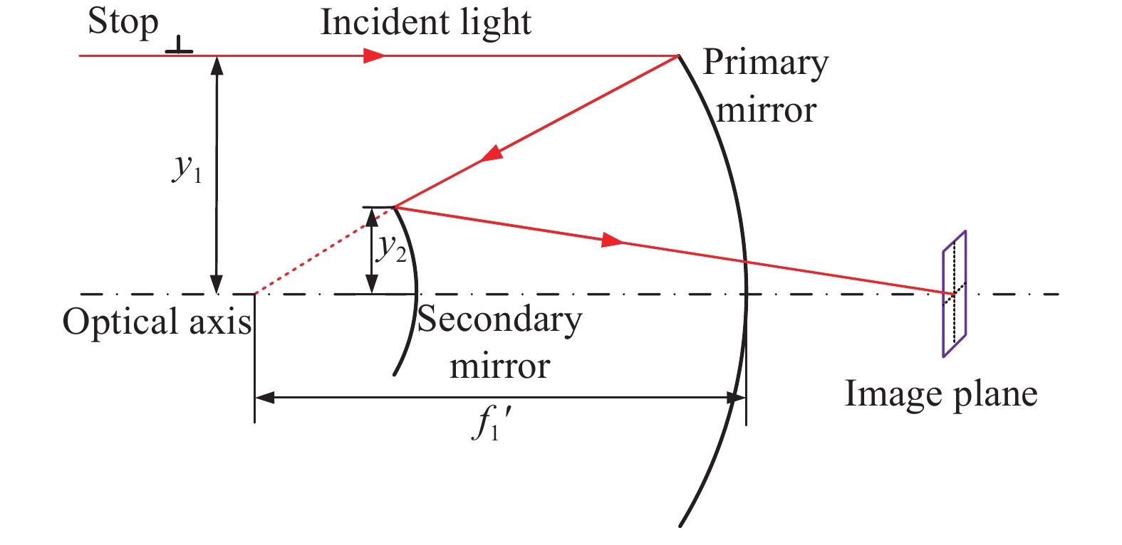
根据初级像差理论求解同轴两反射镜光学系统参数[23],同轴两反射镜光学系统如图3所示。
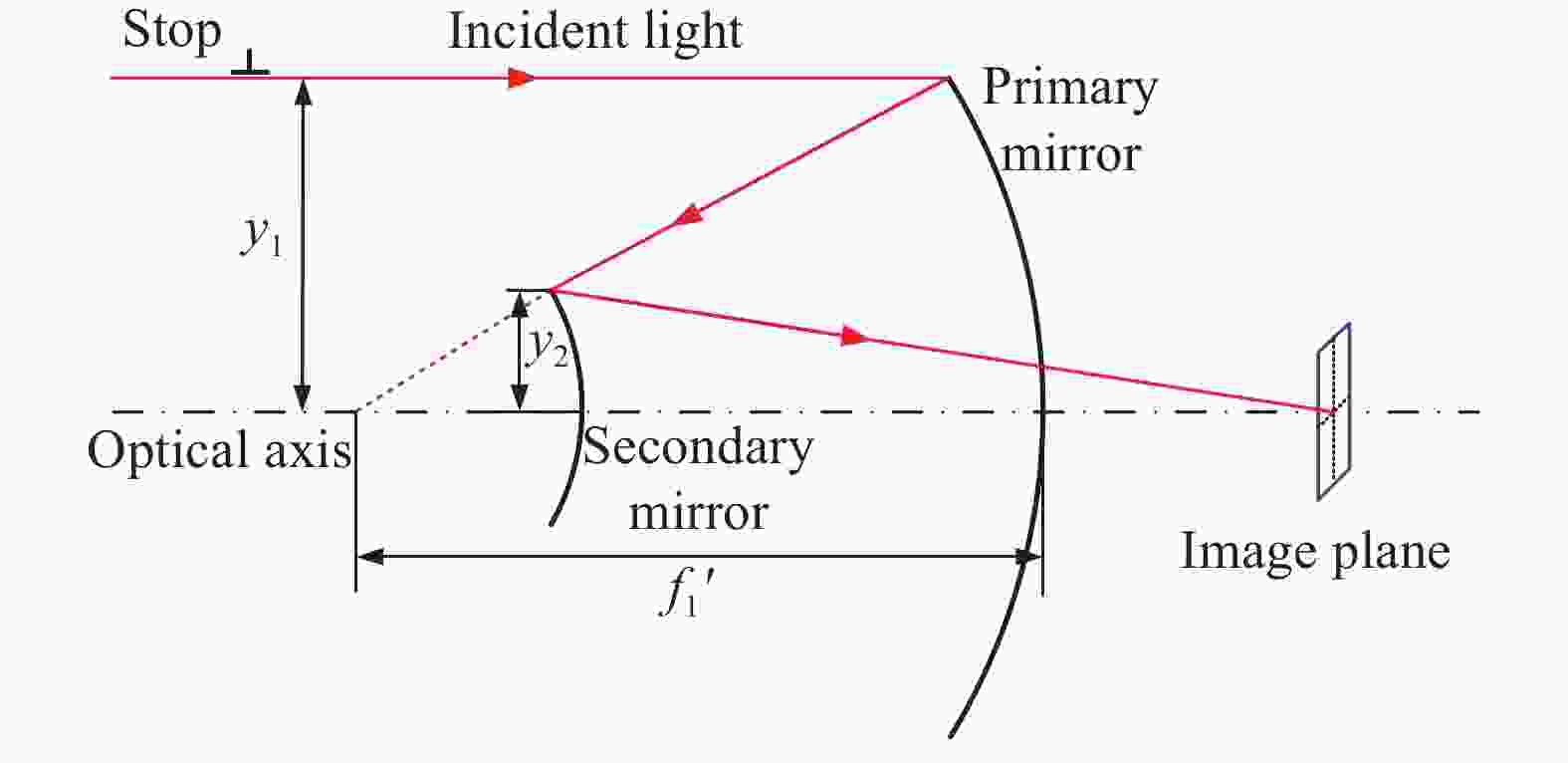
Figure 3. Coaxial two-mirror optical system
轴向遮拦比α、次镜放大率β与光学系统几何参数具有如下数学关系:
式中:y1为主镜半口径大小;y2为次镜半口径大小;f '为系统焦距,f1'为主镜焦距。
当球差和彗差为零时,即可求得k1、k2分别为:
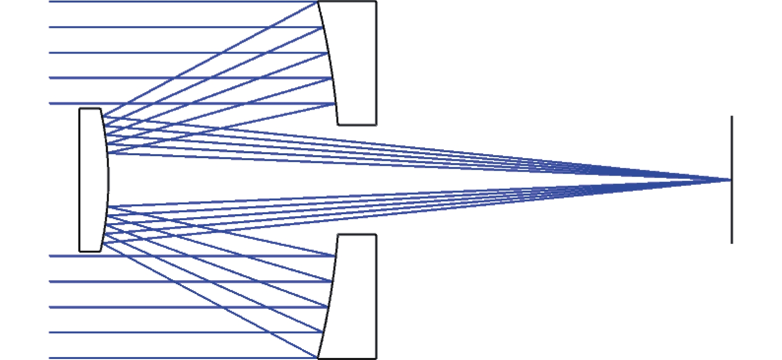
通过对光学系统要求的分析,设定次镜对主镜的遮拦比α=0.35,次镜放大率β=−5,考虑最终设计需要在两反光学系统后工作距中加入校正镜实现像差校正,故要求初始结构的后工作距大于80 mm,通过计算即可获得同轴两反射镜光学系统的初始系统,系统的布局图如图4所示。
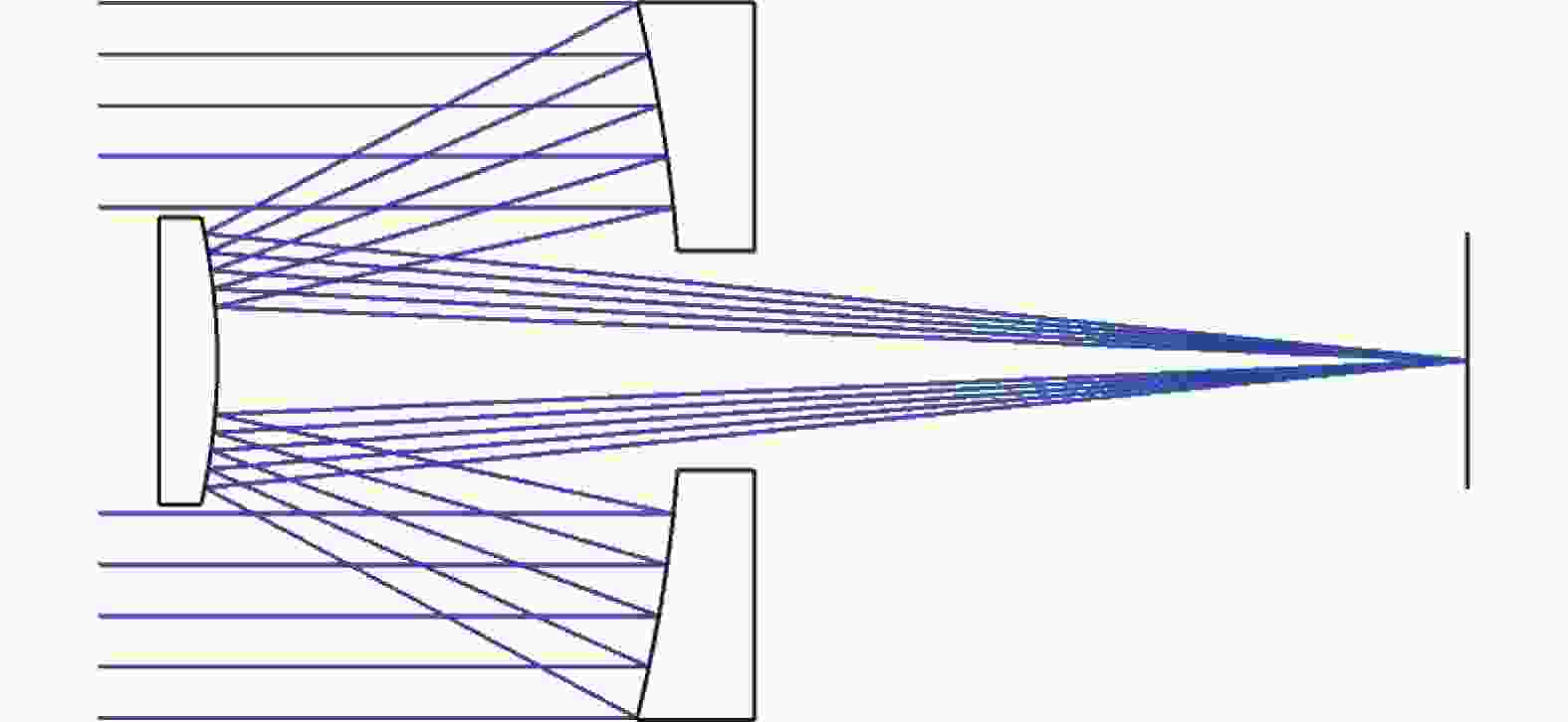
Figure 4. Initial system layout of the coaxial two-mirror optical system
-
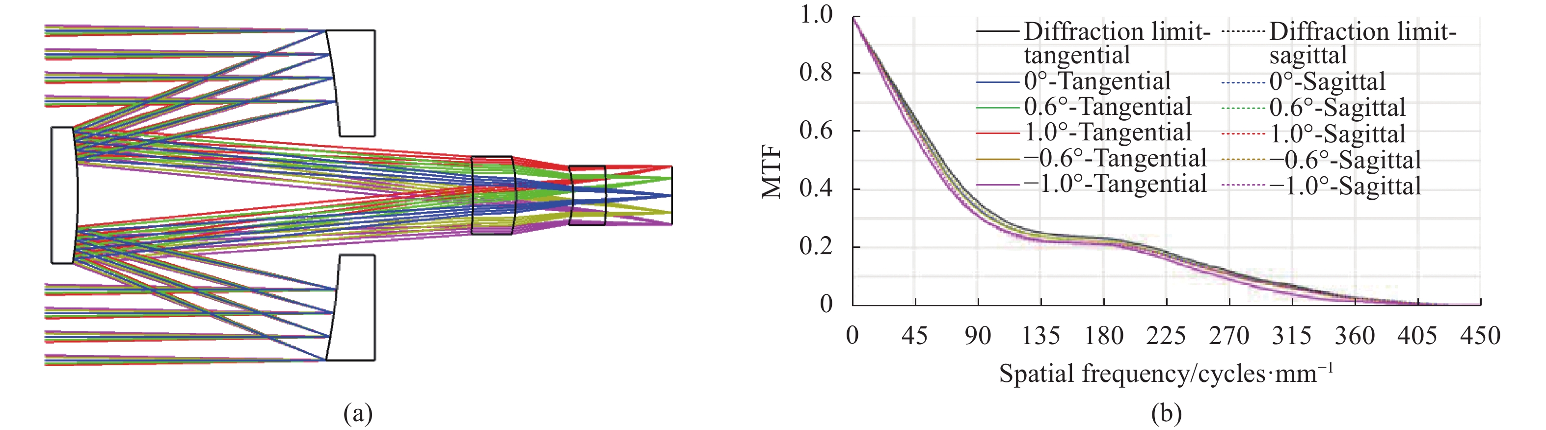
设计采用逐步增大视场的方法[24],首先将视场扩大为2ω=2°,增加由两片透镜构成的校正镜组,将光学镜面的曲率半径和间隔设置为优化变量,初步优化设计结果显示,在2°视场范围内,光学系统成像质量好,实现近衍射限成像,布局图和MTF图如图5所示。
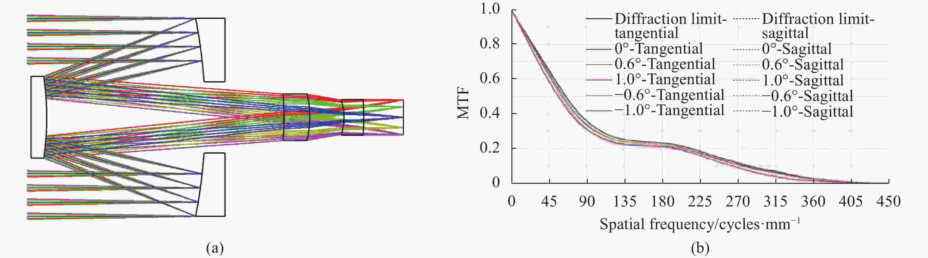
Figure 5. Catadioptric optical system with two correcting mirrors in a 2° field of view. (a) Layout diagram; (b) MTF diagram
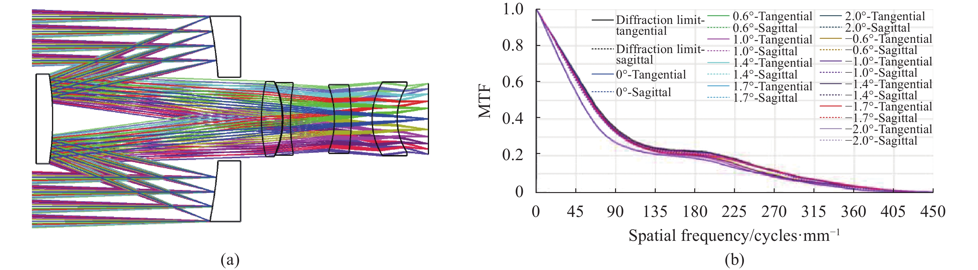
在视场2ω=2°设计结果的基础上,将光学系统视场扩大至2ω=4°,此时两片校正镜构成的校正镜组校正能力不足,球差和畸变较为严重,为了校正像差,将校正镜组增加至四片透镜,随后对校正镜组中所有透镜表面的曲率半径和厚度进行优化,优化过程要保证透镜的可加工性,且总长不能大于180 mm,优化之后的光学系统布局图和MTF图如图6所示。

Figure 6. A catadioptric optical system with four correcting mirrors in a 4° field of view. (a) Layout diagram; (b) MTF diagram
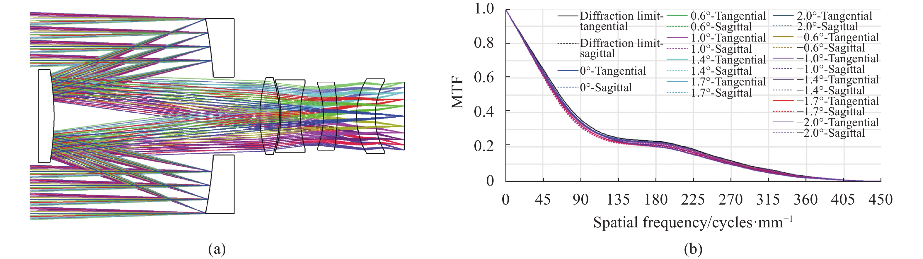
此时的光学系统成像质量稍差,未能实现近衍射限成像。通过分析,此时光学系统的球差未得到充分的校正,可以通过将一个透镜面设置为偶次非球面的方法来提高成像质量,使MTF接近衍射极限。通过寻找最佳非球面的方法,设定校正组中距离像面最远的第一片透镜的前表面为六阶偶次非球面,再次进行像质优化,优化后光学系统的成像质量良好,MTF接近衍射极限,至此降敏设计流程中的第(2)步流程完成,将所获得的光学系统命名为“系统1”作为降敏优化的起点,进入后续的降敏设计流程。“系统1”的布局图和MTF图如图7所示。

Figure 7. Optical system optimized for image quality – “System 1”. (a) Layout diagram; (b) MTF diagram
-
在降敏设计中,为了设定该系统的误差敏感度判断阈值EV,随机生成了1000个满足技术指标要求且像质良好的光学系统,对这些系统进行误差敏感度统计,发现误差敏感度EV分布于(0.253,0.500)之间,为了获取误差敏感度优于系统自动设计的结果,设定目标设计的误差敏感度判断阈值EV=0.240。
对“系统1”进行误差敏感度评价函数构建,光学系统由主镜、次镜、四个校正透镜的前后表面组成,因此误差敏感度评价函数中的光学表面数n=10;对2ω=4°视场对称地选择了11个视场点,分别为−2°、−1.7°、−1.4°、−1°、−0.6°、0°、0.6°、1°、1.4°、1.7°、2°,因此误差敏感度评价函数中视场数m=11。计算得“系统1”的综合误差敏感度ES,F=0.328>0.240,不满足阈值EV,因此需要对“系统1”进行误差敏感度优化。
降敏优化不是一蹴而就的,将“系统1”降敏优化设计过程分为三个阶段,第一阶段设定误差敏感度目标为0.300,对系统中所有光学表面的曲率半径和厚度进行优化,获得“系统2”,“系统2”的ES,F=0.292<0.300,其结构布局如图8(a)所示,MTF如图8(d)所示。接下来将误差敏感度目标设定为0.250,继续对光学系统进行降敏设计,获得“系统3”,“系统3”的ES,F=0.250,其结构布局如图8(b)所示,MTF如图8(e)所示。最后将目标设定为小于0.240 (EV),再次对系统进行降敏优化,获得最终结果,命名为“系统4”,“系统4”的ES,F=0.228,其结构布局如图8(c)所示,MTF如图8(f)所示。
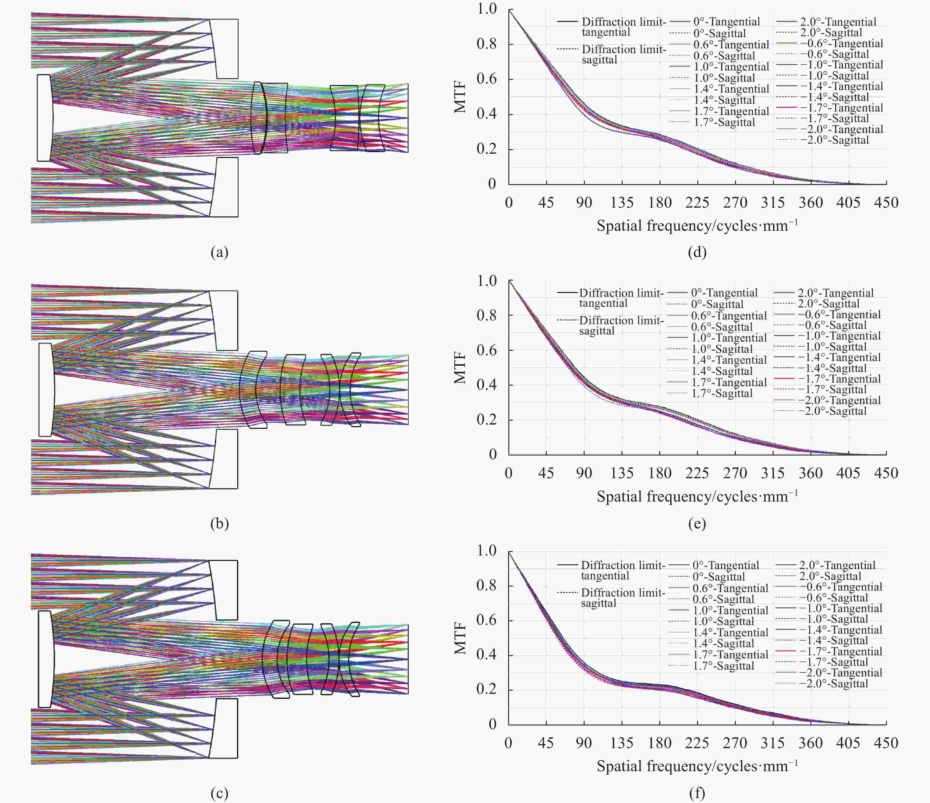
Figure 8. System layout and MTF diagrams during error sensitivity optimization. (a) “System 2” layout; (b) “System 3” layout; (c) “System 4” layout; (d) “System 2” MTF diagram; (e) “System 3” MTF diagram; (f) “System 4” MTF diagram
-
误差敏感度优化过程中所获得的四个阶段性结果均具有良好的成像质量,实现了近衍射限成像。但是根据所提出的敏感度评价函数,这四个光学系统的ES,F数值分别为0.328、0.292、0.250和0.228,误差敏感度鲁棒性依次增强。
为了验证与展示敏感度评价函数与设计的有效性,对四个系统进行误差敏感度分析,采用蒙特卡洛的方法,样本数量为1000,对四个光学系统的每个光学表面施加子午方向倾斜±0.01°、弧矢方向倾斜±0.01°的随机误差,统计MTF的退化情况。“系统1”、“系统2”、“系统3”、“系统4”的MTF蒙特卡洛统计结果分别如图9 (a)~(d)所示。以空间频率100 lp/mm为例进行数据分析,降敏设计前单纯采用光学设计软件优化获得的“系统1”在误差扰动下,MTF有90%的概率大于0.081,有50%的概率大于0.171,有10%的概率大于0.293。应用提出的敏感度评价函数与降敏设计方法所实现的“系统4”在误差扰动下,MTF有90%的概率大于0.351,有50%的概率大于0.386,有10%的概率大于0.406。在误差扰动下,90%的概率“系统4”的MTF比“系统1”高出0.270。“系统1”至“系统4”的MTF蒙特卡洛概率统计如图10所示。
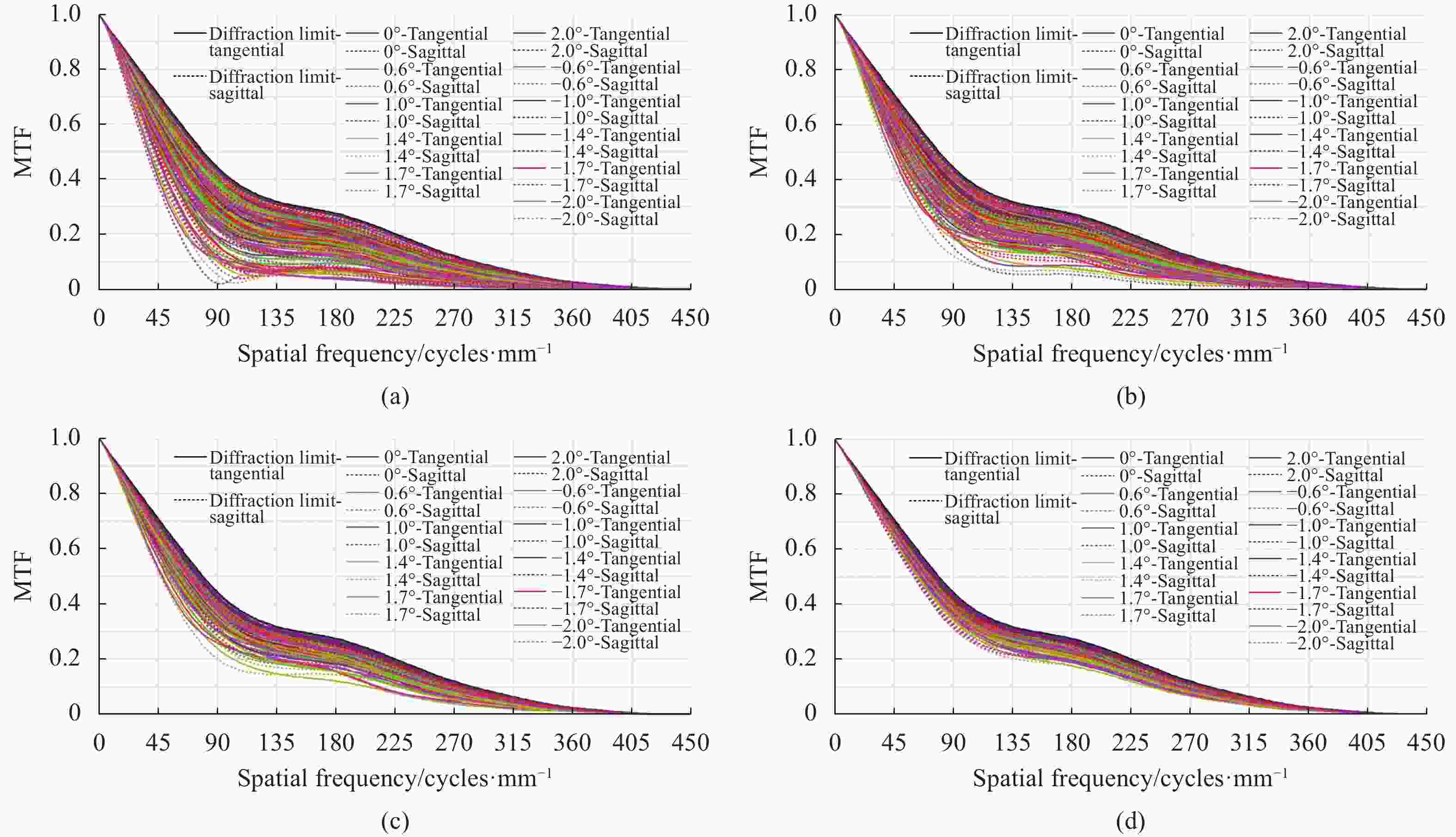
Figure 9. Monte Carlo analysis results of “System 1”, “System 2”, “System 3” and “System 4”. (a) “System 1”–The system before desensitization optimization; (b) “System 2”; (c) “System 3”; (d) “System 4”–Optimal system
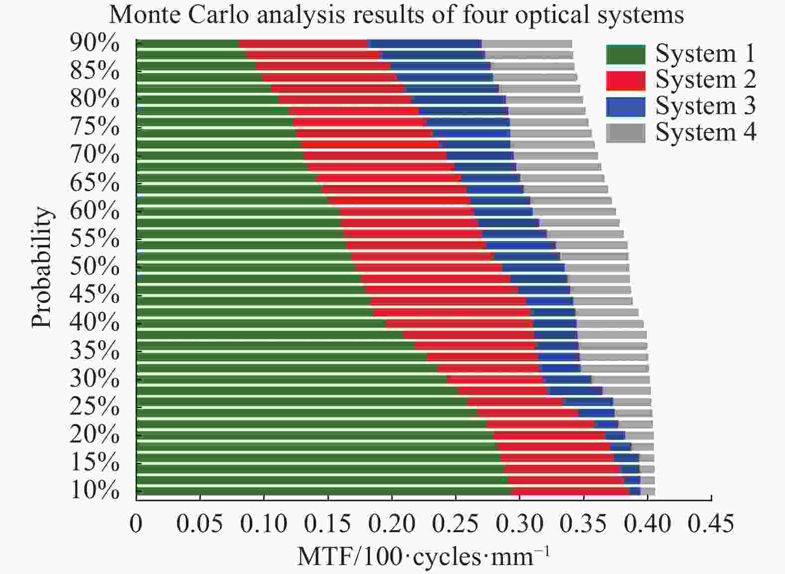
Figure 10. MTF Monte Carlo analysis result diagram from “System 1” to “System 4”
-
文中以焦距为500 mm、视场角为2ω=4°的小型空间相机研制为背景,应用光学系统降敏设计方法(低误差敏感度设计方法)对同轴两镜折反射式光学系统进行了设计,结果表明,基于降敏设计方法获得的光学系统不仅像质良好,MTF接近衍射极限,而且具备较强的抵抗误差干扰的能力。在相同的误差干扰影响下,降敏优化后的系统(“系统4”)的MTF下降明显小于降敏前的系统(“系统1”),蒙特卡洛分析结果显示,“系统1”的MTF有90%的概率大于0.081,而“系统4”的MTF有90%的概率大于0.351,“系统4”的MTF比“系统1” 的MTF高出0.270,提升约4.33倍。
光学系统降敏设计方法的提出与应用提升了光学系统抵抗误差干扰的能力,可以有力保障高性能小型空间光学相机研制的快速化与低成本化,对空间光学载荷的研制具有重要意义。
Low error-sensitive design of small-sized high-resolution space camera optical system
doi: 10.3788/IRLA20220365
- Received Date: 2022-05-30
- Rev Recd Date: 2022-07-06
- Available Online: 2022-11-02
- Publish Date: 2022-10-28
Fund Project:
Younth Innovation Promotion Association CAS(2019219);CAS Support Plan for Youth Team Program in Basic Research(YSBR-066);National Natural Science Foundation of China(61705220)
-
Key words:
- space camera /
- optical system design /
- error sensitivity /
- desensitization design method /
- catadioptric optical system
Abstract: Systematically adopting strict control over the processing and assembly accuracy of optical elements, adopting high-quality and stable opto mechanical structure, and using precision thermal control are the conventional methods to ensure the high performance imaging quality of the optical system of space cameras in the past, but at the same time, the implementation of this strategy also brings high economic and resource costs to camera development. In the face of the development trend of low-cost high-performance space optical cameras, reducing the error sensitivity of the optical system and lowering the implementation cost while ensuring the imaging performance are the issues that need to be faced and solved. In this paper, a compact space camera as a background, and the low error-sensitivity design method (desensitization design method) is applied to a coaxial two-mirror catadioptric optical system with a focal length of 500 mm, a relative aperture of 1 : 5, and a field of view of 2.75°×2.75°. The results show that the optical system, based on the desensitized design method, not only gets excellent aberration correction theoretical results and modulation transfer function which is close to the diffraction limit, but also shows that the optical system is robust under the error interference in the simulation, which provides a guarantee for the rapid and low-cost manufacturing of the camera. The optical system desensitization design method has an important application value for the design and rapid development of high-performance small space loads at low cost.


 DownLoad: