


-
随着红外技术的发展,航空航天领域、军事领域等对探测目标的空间分辨率、时间分辨率、辐射分辨率以及波段特性的要求越来越高。这些指标要求红外焦平面技术需要向着扩大探测波长范围、减小光敏元尺寸、增加探测器规模的方向发展[1]。于是扫描式长线列、凝视型大面阵以及多模块拼接式超大面阵红外焦平面探测器得到发展[2-4]。随着红外探测器规模的增大,拼接的探测器阵列规模越来越大,拼接基板(冷平台)的尺寸也随之增大,从小型的几十毫米,增大到几百毫米,甚至未来的几千毫米。尺寸增大引入的组件各结构的质量增加、温度均匀性变差、漏热量增大等各种问题不容忽视。因此,对于冷平台的支撑结构性能要求也随之提高,超大冷平台支撑的设计需要足够的刚度以满足超大面阵红外探测器组件的力学环境振动要求,同时支撑结构需要具有较高的热阻值,减少冷平台通过支撑的传导漏热量,以满足冷平台的高温度均匀性要求。这些难点都对超大面阵冷平台的支撑结构的设计提出了新的挑战。
目前,Xavier等[5]针对METOP-SG卫星的SWIR和VNIR组件的冷平台支撑结构进行优化设计,其以组件基频为500 Hz,支撑结构热阻为200 K/W为条件对11种支撑结构进行筛选设计,最终选取6足杆式支撑作为最终的结构。陈芳等[6]采用新型的玻璃纤维束作为截面直径为
$\varPhi 68 $ mm的杜瓦冷指的支撑结构,该结构相比于传统结构热阻提高了3730倍,且通过了均方根5 g RMS的随机振动试验,组件的基频达到了358 Hz。李俊等[7]报道了对16个512×512探测器拼接而成的超长线列探测器的冷平台支撑结构进行设计,最终采用优化了厚度和圆锥角等参数的钛合金材圆锥结构,组件结构通过了7.17 g RMS的随机振动测试,并且热学性能良好。而国内对于拼接式超大规模的面阵探测器冷平台支撑结构的相关文章还未见详细报道。文中根据超大规模的面阵红外探测器的冷平台力学和热学性能要求,提出了一种对称式八杆的冷平台支撑结构,并对支撑结构参数进行优化,利用氧化锆陶瓷的低热导率、高刚度等优点,解决了超大冷平台组件的高力学性能需求和低漏热要求的问题,设计出了可适用于各种类型的超大规模冷平台的支撑结构。
-
某航天项目的探测器焦面规模达到6 k×6 k,冷平台面积达到40000 mm2,虽然冷平台采用新型的陶瓷材料,但是最终的冷平台以及冷平台上探测器模块、辐射屏等结构的总质量依然达到3 kg。超大规模面阵红外探测器的冷平台组件结构如图1所示,主要由探测器模块、冷平台、支撑结构、底板等结构组成。
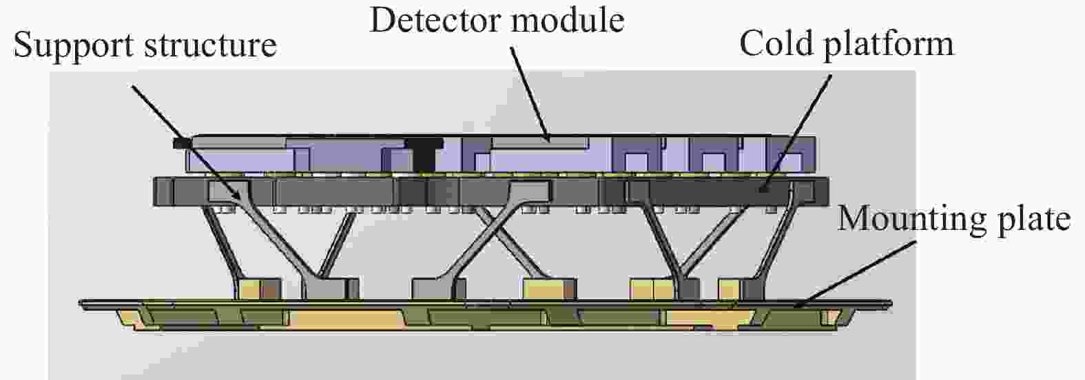
Figure 1. Schematic diagram of the structure of the super large-scale area array focal plane cold stage assembly
随着冷平台面积、质量的增加,支撑结构的刚度也需要提高,因此其横截面积不可避免地增加,但是支撑结构的两端,一端为100 K以下温度的冷平台,另一端则为室温端。两端温差较大,因此会产生不小的通过支撑的传导漏热。因此在对支撑机构进行设计时,既需要考虑组件的结构刚度,也不能忽视因此产生的漏热量增加。基于项目的杜瓦漏热要求,通过支撑的传导漏热要求在室温条件下小于0.5 W的漏热量。其次超大规模面阵红外焦平面组件需要具有较高的环境适应性,根据工程经验,冷平台组件的力学性能要求,组件的共振频率要求300 Hz以上,需要通过30 g的空间力学载荷测试、总均方根为9 g RMS的XYZ三个方向的随机振动等力学环境试验[8]。
文中采用有限元仿真分析的方法,对不同支撑结构的冷平台组件进行模态分析、30 g静力学载荷分析、随机振动分析。并根据组件的模态基频,静力学载荷下的最大应力,支撑结构的热阻等,综合评价各组件的力学性能和热学性能。为支撑结构的参数选择提供依据。支撑结构的初步设计如图2所示。可优化的参数分别有支撑的高度H、宽度M、厚度N,支撑的安装倾角θ以及支撑结构的材料。

Figure 2. Design drawing of support structure of cold platform components
模态分析用于提取结构的动态特性。可以用于确定超大规模冷平台组件的固有频率和各阶振型,组件的模态频率能够表征组件的抗力学振动性能。对于多自由度的自由振动系统的作用力方程[9]:
式中:
$M$ 为系统的质量矩阵;$ C $ 为系统的阻尼矩阵;$K$ 为系统的刚度矩阵;$ \ddot X(t) $ 、$ \dot X(t) $ 、$ X(t) $ 分别为系统的广义加速度、速度、位移。系统的动能分为平动动能和转动动能,总动能表示为:式中:
${i_x}$ 、${i_y}$ 、${i_z}$ 为冷平台在$\{ M\} $ 坐标系的速度分量;$\{ M\} $ 坐标系为全局坐标系,原点位于底板中心;${I_{xx}}$ 、${I_{yy}}$ 、${I_{zz}}$ 为冷平台在$\{ M\} $ 坐标系的转动惯量矩阵;$\alpha $ 、$\;\beta $ 、$\gamma $ 为冷平台在$\{ U\} $ 坐标系绕各轴的旋转角,$\{ U\} $ 坐标系为冷平台坐标系,原点位于冷平台中心;$\dot \alpha $ 、$\;\dot \beta $ 、$\dot \gamma $ 为冷平台在$\{ U\} $ 坐标系的角速度矩阵。质量矩阵可以通过系统总动能对系统的广义速度的微分求得:
系统的刚度矩阵由系统的势能
${E_u}$ 对系统广义速度的微分求得:式中:
${k_i}$ 为每个支撑的等效刚度,${k_i} = \dfrac{{3 EJ}}{{{L^3}}}$ ;$E$ 为支撑材料的弹性模量,$J$ 为支撑结构的截面模量,对于矩形截面而言:$J = \dfrac{1}{{12}}M{N^3}$ ;$\Delta {l_i}$ 为支撑受外界载荷的变形量[10]。求解微分方程:假设
$X = \phi \sin (\omega t)$ ,$\phi $ 为系统模态,$\omega $ 为系统的固有频率。方程简化为:
该方程为特征方程,求得的特征值为系统的固有频率,特征向量为系统的模态频率[11]。
由于超大面阵杜瓦内部为真空状态,支撑结构的漏热主要包括辐射漏热和传导漏热,一般支撑结构表面发射率较低,且文中讨论的不同支撑结构之间的表面积差距较小,引起的辐射漏热量的变化不大。因此主要考虑支撑结构之间的传导漏热差异,在对支撑进行热力学分析,支撑两端温差较大,支撑传热面积较小,可以近似简化为一维热传导问题,由傅里叶定律可得[12-13]:
式中:A为传热面积;L为支撑结构的传热路径长度;K为高低温端之中的平均热导率,其可由方程得出:
支撑结构的等效热阻为:
为增大支撑结构的热阻,一是可以增大支撑结构的传热路径L或是减小支撑结构的横截面积A,但是这会降低支撑的结构刚度,不利于组件的力学性能;二是可以选择低导热、高刚度的材料作为支撑材料[13]。表1为几种常见的封装材料和新型氧化锆材料的性能参数。其中热导率为300~77 K之间的平均值[7, 14-15]。文中的仿真材料参数也采用表1的数据。
Material Density/kg·m−3 Thermal conductivity/W·m−1·K−1 Elastic modulus/GPa Poisson’s ratio $\varepsilon $ Parts TC4 4440 4.2 109 0.32 Supporting structure, mounting plate Kovar 8360 17 200 0.3 Supporting structure ZrO2 5740 3 210 0.3 Supporting structure SiC 3080 490 466 0.32 Cold platform Table 1. Dewar packaging material parameters
由上述分析可知,系统的固有频率与支撑结构的长度L,宽度M和厚度N,支撑与XOY面(安装板)的倾角
$\theta $ 以及支撑的高度H有关,支撑的导热特性与支撑的导热路径L,支撑的截面积A有关。因此下文将基于有限元分析,通过改变支撑的这些参数,并对仿真结果进行对比分析,为支撑结构的参数选择提供依据。 -
图3汇总了支撑结构的四项参数对于冷平台组件的影响。图3(a)为材料和支撑宽厚比对于组件的影响,控制支撑的横截面积为7.5 mm2,宽厚比范围为从1.875~12,选取7个对比组。仿真分析结果如图所示,可以发现,随着宽厚比增大,冷平台组件的最大静力学应力也逐渐增大,然后趋于平稳,存在一个最大值,应力最小值为40.54 MPa,最大值为50.16 MPa,应力值增幅为23.7%。随着宽厚比的增大,冷平台组件的模态基频也从546.23 Hz增加至569.8 Hz,增幅为4.3%。对于冷平台组件的力学性能而言,组件的最大静力学应力越小越好,模态基频越大越好,这两个参数随着支撑横截面的宽厚比增加,呈现相同的增长趋势,但是静力学应力的增幅较大,而组件模态基频的增幅较小,甚至可以忽略。因此在考虑支撑的可加工性的基础上,横截面的选取低宽厚比的方案,对于组件的力学性能优化更好。

Figure 3. Influence of support structure aspect ratio (a), height (b), installation inclination (c), material (d) on components
由图3(b)、(c)可以看出,随着支撑安装高度的增加,支撑结构的热阻从196 K/W增大至337 K/W,随着安装支撑倾角从30°增大到60°,支撑结构的热阻从317.47 K/W降低到183.29 K/W,这是因为在不同的安装高度下,随着高度增加,支撑结构的长度会增加;在相同的安装高度情况下,随之支撑倾角的减小,支撑的长度也随之增大,支撑结构的传热路径增长,从而导致热阻增大,使冷平台组件的传导漏热减小,有利于冷平台上各个探测器模块的高温度均匀性。但是在相同倾角下,随着支撑结构的安装高度增加,冷平台组件的模态基频从590 Hz降低到437 Hz,降低幅度约为25%。并且随着支撑结构安装高度的增加,冷平台组件的整体结构尺寸也会随之增加,导致最终的探测器杜瓦组件的尺寸也会变大,最终整体重量会增加。在相同的支撑高度下,冷平台组件的模态基频随着支撑倾角的增大,呈现出先增大后减小的趋势,在倾角为40°左右的位置存在一个最大值。因此,对于大规模冷平台的支撑倾角的设计时,倾角为40°时,可以使冷平台组件的模态基频最大。若是需要降低组件的传导漏热,则可以通过减小支撑倾角的方式来实现,但是考虑组件的尺寸限制,倾角存在一个最低值。因此支撑结构的安装高度、安装倾角,首先需要在满足探测器组件的空间力学要求的基础上,综合冷平台组件的模态基频、传导漏热、组件的轻量化设计、组件尺寸等方面考虑,优化选择合适的安装高度和倾角。
图3(d)显示了不同的材料对于组件的影响,可以发现采用kovar和TC4材质支撑的冷平台组件的模态基频相近,而采用了氧化锆材质支撑结构的冷平台组件的模态基频相较于kovar和TC4材质提高了22%。相较于kovar材料,TC4和氧化锆材料的低温热导率值较低,因此这两种材料的支撑结构的热阻值较大,带来的漏热量会更小。因此不论从力学性能,还是结构热阻来看,氧化锆材料均要优于其他两种材料。
图4为不同参数组别的组件基频、应力以及结构热阻的综合对比,图中每一点代表一组不同参数的结构,X轴表示30 g静力学载荷下的组件的最大应力,Y轴代表组件的模态基频,Z轴代表支撑结构的热阻值。为了达到三个指标的最佳设计值,结构的代表点须在图中的立体框内:基频>530 Hz、应力值<50 MPa、热阻值>200 K/W。从图中可以看出一共有四组结构符合要求,从中选取一组作为代表组进行实物验证。

Figure 4. Comprehensive analysis diagram of component fundamental frequency, stress and structural thermal resistance for different parameter groups
-
基于以上分析结果,优选一组合适的支撑结构参数,如表2所示。并设计实际的冷平台组件结构,对组件进行5~2 000 Hz的正弦扫频试验、总均方根为9 g RMS的XYZ三个方向的随机振动试验,并与仿真结果进行比较,用以验证仿真方法的准确性和冷平台组件的力学设计与力学可靠性。
Parameter Material N
/mmM
/mm$\theta $
/mmH
/mmValue ZrO2 2 3.75 40 40 Table 2. Support structure parameters of the actual cold platform components
图5为冷平台组件模态分析前6阶振型图。冷平台组件的第1、2阶振型沿水平面的平移振型;第3阶振型为冷平台沿Z方向平移振型;第4阶表示沿Z轴旋转振型;第5、6阶表示沿水平面翻转振型。

Figure 5. The first six-order mode shape diagram of the ultra-large cold platform components
力学试验装置如图6所示。冷平台组件分别进行了三个方向的扫频测试,X、Y、Z三个方向的响应频率分别为557、577.12、764 Hz。仿真与测试结果对比如图7(a)所示,以试验值为基准,可以得出三个方向的仿真结果与试验测试值的误差为10.6%、6.8%、15%。由于仿真时约束是在设置在底板处的固定约束,而实际测试时,并无完美的固定约束,因此仿真结果的组件基频略微偏大。试验结果表明,仿真模型可以有效的预测实际结构的模态频率。

Figure 6. Photo of vibration testing process of ultra-large cold platform components
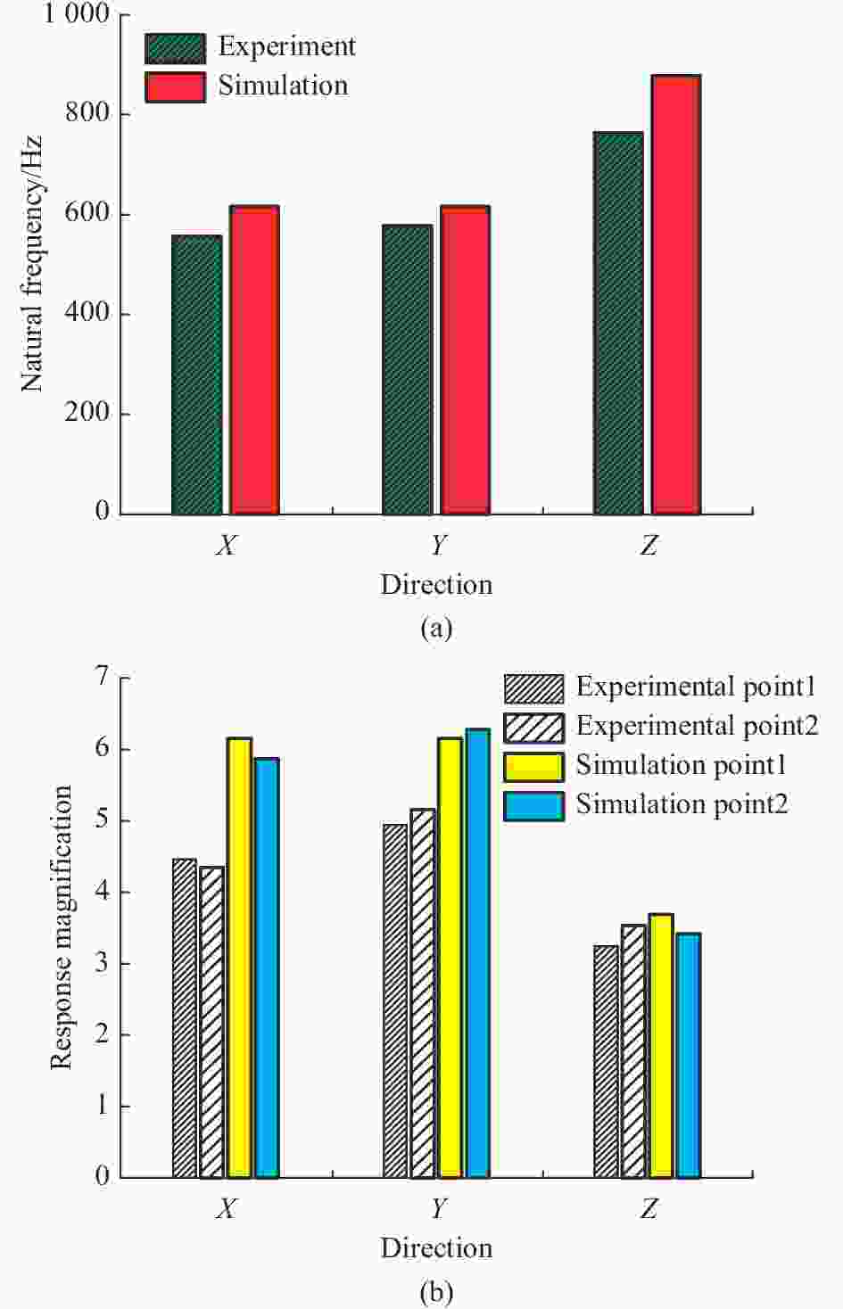
Figure 7. Simulation analysis and vibration test results comparison of ultra-large cold platform components
随机振动试验的关键测点的加速度响应的放大倍数的仿真与测试对比见图7(b),分别进行了X、Y、Z三个方向的随机振动试验。取两个典型测点进行仿真和测试数据的对比,结果如图7(b)所示。以试验测试值为基准,可以得出三个方向的随机振动加速度响应的放大倍数的仿真数据与试验值的误差最大为37.8%,最小误差为3%。X方向的随机振动测试时,两测点加速度响应的放大倍数分别为4.46、4.35。Y方向的随机振动测试时,两测点的加速度响应分别为4.94、5.16。Z方向的随机振动测试时,两测点的加速度响应分别为3.25、3.53。三个方向的加速度响应倍数均小于10,表明冷平台组件在随机载荷的激励下,结构的可靠性能够满足要求。并且经仿真分析验证,支撑结构在100 g的强冲击响应谱作用下,三个方向的最大应力为230 MPa,而氧化锆陶瓷的屈服极限为650 MPa,能够通过100 g冲击试验。
-
对超大规模面阵红外探测器的冷平台组件的支撑结构采用了高强度、低热导率的新型氧化锆材料并对结构进行优化设计,对支撑结构的参数进行了全方面的仿真对比分析,通过优化支撑结构的宽厚比、高度、倾角以及材料,对结构的各项参数进行取舍,以此平衡超大规模冷平台组件既需要高力学可靠性,又需要低漏热,高温度均匀性的需求。同时,采用文中支撑结构的冷平台组件通过了正弦振动试验和总均方根为9 g RMS的随机振动试验,且试验结果与仿真结果吻合较好,验证了该结构的可行性。为超大规模红外探测器组件的支撑结构设计提供了指导。
Research on the supporting structure of the cold platform of the large format infrared detector
doi: 10.3788/IRLA20220445
- Received Date: 2022-07-20
- Rev Recd Date: 2022-08-10
- Publish Date: 2023-02-25
Fund Project:
Key Project of CAS (ZDRW-CN-2019-3) and the Youth Innovation Promotion Association, Chinese Academy of Science (2018274)
-
Key words:
- large format infrared detector /
- support structure /
- Dewar packaging /
- cold platform
Abstract: In order to meet the space application requirements of the large format Mosaic infrared detector, ultra-scale cold platform need to work at low temperatures, and the cold platform support structure requires high rigidity to meet the components' anti-vibration performance, and a high structure thermal resistance to reduce its conduction heat leakage. A symmetrical eight-bar structure is proposed as the cold platform support, which adopts a new type of zirconia ceramic material with high strength and low thermal conductivity. Based on the finite element software, the influence of the height of the support structure, the installation inclination angle, the aspect ratio and the material on the modal fundamental frequency of the module, the thermal resistance of the support structure and the maximum stress of the module under 30 g static load are analyzed. A set of parameters is used to design the actual test component, the thermal resistance of the support structure reaches 220 K/W, and the components are subjected to a 5-2 000 Hz sine frequency sweep test, a total root mean square of 9 g RMS, and random vibration in the three directions of XYZ and other mechanics. In the environmental test, the final component passes the experimental verification of space environment adaptability. The fundamental frequency of the component reaches 560 Hz, and the test results are in good agreement with the simulation results. The results show that the symmetrical eight-rod zirconia support structure solves the problem that the cold platform of the large format infrared detector requires both high mechanical properties and low heat leakage, and meets the needs of engineering applications.


 DownLoad: