


-
计算全息图(computer-generated hologram,CGH)由于其补偿范围大、设计灵活、加工精度高等特点被广泛应用于非球面和自由曲面的检测[1-4],计算全息图的工作原理基于光的衍射,使用级次的衍射效率影响实际使用效果。常规振幅型计算全息图衍射效率仅可达到10%,光线双次经过计算全息图其能量利用率不足1%,该能量利用率仅仅可以完成高反射率材料如碳化硅、硅、金属等材料反射镜的检测,对于低反射率材料如微晶玻璃、石英等,条纹对比度过差而无法满足使用需求。位相型CGH可以将衍射效率提升至40%,光线双次经过CGH时,光能利用率可以比振幅型CGH提升16倍,但是由于全息图的对准区域是反射光栅,位相型CGH的反射能量很弱会导致对准区域条纹对比度差,不利于现场检测人员使用,尤其是对于一些对准区域需要使用高级次衍射光如3级或5级衍射光的检测方案,其能量会进一步降低而无法找到反射光。基于如上问题,文中提出了混合型计算全息图,一方面对准区域制作成反射型光栅,有利于提升反射级次的能量;另一方面主区域制作成位相型,有利于提升主区域条纹对比度。
目前高精度离轴非球面主要采用零位干涉方法进行检测,零位补偿器分为折射式补偿器和衍射型补偿器(CGH)[5-6],面向离轴高次非球面和自由曲面的检测,CGH相比折射型补偿器具有更大的设计自由度,此外,由于加工使用先进半导体工艺,其检测精度也普遍优于折射型补偿器,被国内外研究机构广泛使用。2007 年,Arizona 光学中心周平博士对CGH检测过程的误差进行了全面系统的分析[7];2013年,Arizona赵春雨博士进一步通过标定基板误差把CGH检测精度提高到优于6 nm[8]。2011年,中国科学院长春光学精密机械与物理研究所(下面简称长春光机所)黎发志博士使用计算全息图完成离轴非球面的检测,精度优于6 nm[9]。2018年,西安工业大学的李世杰博士研究了混合补偿在高陡度非球面检测中的应用[10]。2020年,长春光机所的王若秋博士使用离子束修型设备对位相型计算全息图进行了刻蚀方法研究,论证了更大口径位相型全息图刻蚀的可行性[11]。2021年,长春光机所的白莹莹博士提出一种补偿由多步套刻引入误差的标定方法,论证了多步套刻方式实现大口径CGH制作的可行性[12]。
文中针对低反射率表面,提出了基于混合型计算全息图提升条纹对比度的方法,针对一款微晶材料的离轴非球面进行了计算全息图的设计,使用半导体工艺加工了混合型计算全息图并搭建光路进行了检测实验,主区域和对准区域条纹对比度清晰,利用该CGH完成微晶材料离轴非球面的检测,检测精度优于0.02λ,该混合型计算全息图可广泛应用于低反射率表面的面形检测。
-
待检测非球面是微晶材料离轴抛物面,具体参数如表1所示。
Parameter Value/mm Radius of curvature R
Rex
Rey
X axis decenter
Y axis decenter3803.552
300
300
0
500Table 1. Parameters of off-axis aspheric surface
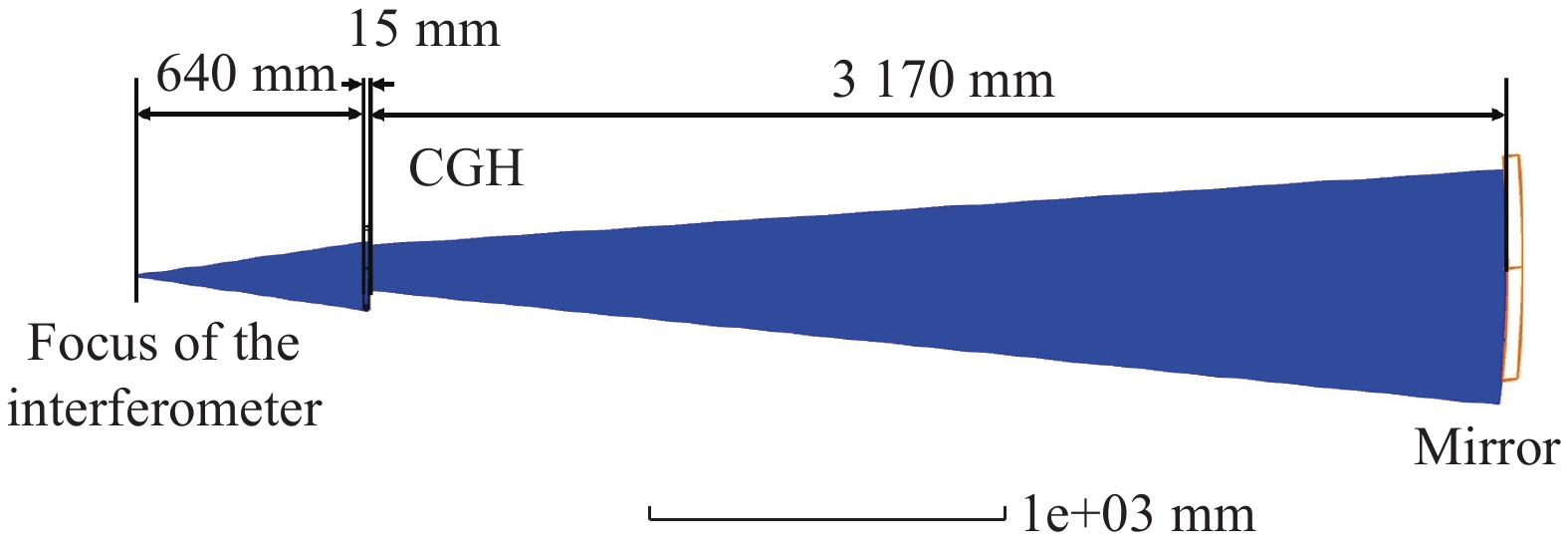
使用Zernike标准面型对计算全息图进行优化,图1为计算全息图的设计光路,标准镜采用4D 4 in(1 in=2.54 cm)F#3.3镜头,干涉仪焦点距离CGH前表面640 mm,CGH后表面距离待检测微晶反射镜中心3170 mm。

Figure 1. Optical path of off-axis aspheric surface interferometric testing by CGH
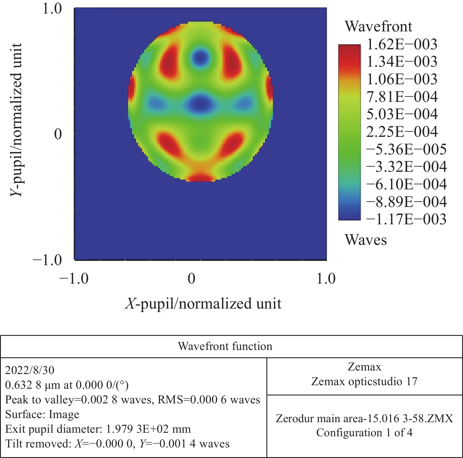
主区域设计波像差残差RMS优于0.0028λ,见图2。

Figure 2. Design residuals of main area
-
对准区域的条纹对比度受反射光栅的衍射效率影响,分别使用相位法和傅里叶变换法对衍射效率模型进行分析。
-
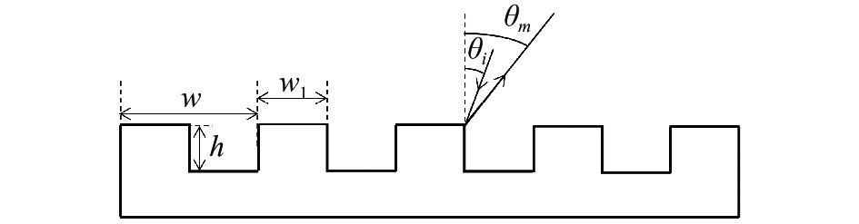
使用线性光栅来表示计算全息图的局部模型,如图3所示。

Figure 3. Model of linear grating
图中,w为光栅周期,w1为光栅顶部宽度,h为刻蚀深度,θi为光栅的入射角度,θm为光栅的出射角。
一个小台阶上的光程差为
$ w_1(\sin {\theta _i} + \sin {\theta _m}) $ ,相邻台阶的光程差为$ w_1(\sin {\theta _i} + \sin {\theta _m}) - h(\cos {\theta _i} + \cos {\theta _m}) $ ,设焦面上存在一点P,只考虑单个台阶P点的复振幅为:式中:
$\alpha = \dfrac{{\pi w_1(\sin {\theta _i} + \sin {\theta _m})}}{\lambda } = \dfrac{\pi }{2}m$ 。相邻台阶,即一个周期的光栅产生的相位差为:
则一个周期的光栅产生的多光束干涉结果为:
则M个周期的光栅产生的多光束干涉结果为:
式中:
$\rho = \dfrac{{2\pi }}{\lambda }w(\sin {\theta _i} + \sin {\theta _m}) = 2\pi m$ ,m为级次。 -
假设光栅周期为w,非刻蚀区域宽度为w1,占空比
$D =w_1/w$ ,刻蚀深度为h,光线经过光栅反射后,刻蚀区的复振幅为A0,非刻蚀区的复振幅为$ {A_1}\exp ( - i\phi ) $ ,其中振幅大小A1由膜层的反射率决定,设刻蚀深度为h,宽度为
$w_1 = w/2$ ,入射角为θi,出射角为θm。式中:λ为波长,空气折射率设为1。
对于垂直入射的平面波,光栅的反射率函数可以表示为:
根据弗朗和费衍射理论,假设在M个周期中,反射后的波前可以表示为:
式中:
$\rho = \dfrac{{2\pi }}{\lambda }w(\sin {\theta _i} + \sin {\theta _m}) = 2\pi m$ ,m为级次。假设反射率相同A0= A1,且D=0.5,经过运算化简得:
显然与相位法完全相对应,得以证明两种方法的正确性。
-
笔者以相位法,通过matlab计算仿真,探究反射率对衍射效率的影响。
选择衍射级次为+1级,入射角设为0°,刻蚀深度为h。
计算得此时光强为:
式中:r为膜层反射率。
根据对比度计算公式[13]:
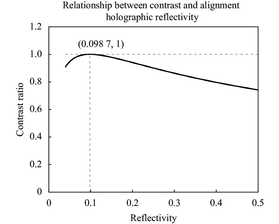
根据此公式在matlab中绘制r在(40%,50%)范围内的对比度图像,见图4。

Figure 4. Relationship between reflectivity of alignment holographic and fringe contrast
根据图4得知,在反射率为9.87%时,对比度达到最大值,此时条纹最清晰,方便检测人员对准。
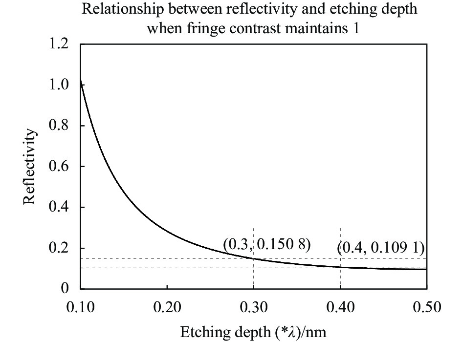
进一步的,笔者将刻蚀深度h设为未知数,希望得到在对比度保持最大值的前提下,刻蚀深度与反射率之间的联系。
修正公式可以获得反射率与刻蚀深度的关系表达式如下:
对比度为1的时候,反射率和刻蚀深度的关系如图5所示。

Figure 5. Relationship between etching depth and reflectivity when fringe contrast maintains 1
由于工艺原因,刻蚀深度为0.5λ时,CGH对刻蚀误差非常敏感,因此在实际加工中,笔者一般选用刻蚀深度为0.3λ~0.4λ[14]。根据图像分析,也非容易界定该范围的反射率值。
-
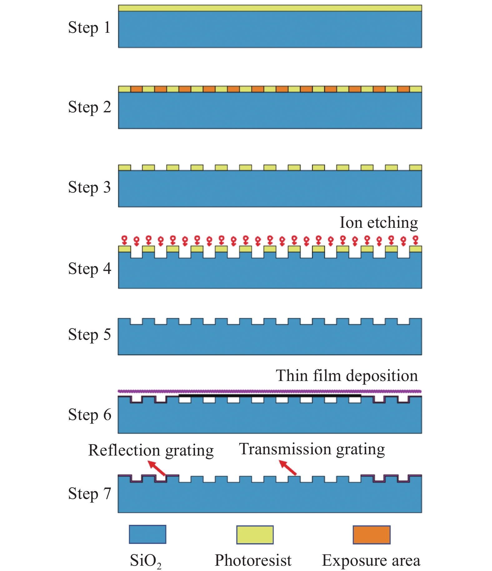
常规振幅型计算全息图和位相型计算全息图的加工方式已有多篇论文报道,文中提出一种对准区域高对比度的混合型计算全息图加工方法,其加工流程如图6所示:第1步,在石英玻璃基底旋涂500~600 nm厚度AZ1500光刻胶;第2步,使用激光直写设备将设计的计算全息图曝光在光刻胶上,文中使用海德堡公司生产的DWL66+设备进行曝光;第3步,放入显影液中进行显影,曝光部分被去除,在石英表面形成光刻胶图形;第4步,以光刻胶为掩膜进行干法刻蚀,刻蚀气体为三氟甲烷(CHF3)和氧气的混合气体;第5步,使用丙酮去除步骤4工艺步骤后表面残留的光刻胶,此时,已经完成位相型计算全息图的加工;第6步,使用金属掩膜对主衍射区域进行遮挡镀反射膜;最终形成第7步所示的混合型计算全息图。

Figure 6. Fabrication process of hybrid type CGH
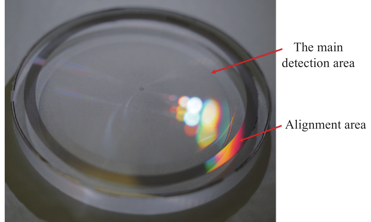
按照如上步骤对设计的计算全息图进行加工,加工后的计算全息图如图7所示。

Figure 7. Physical of hybrid type CGH
-
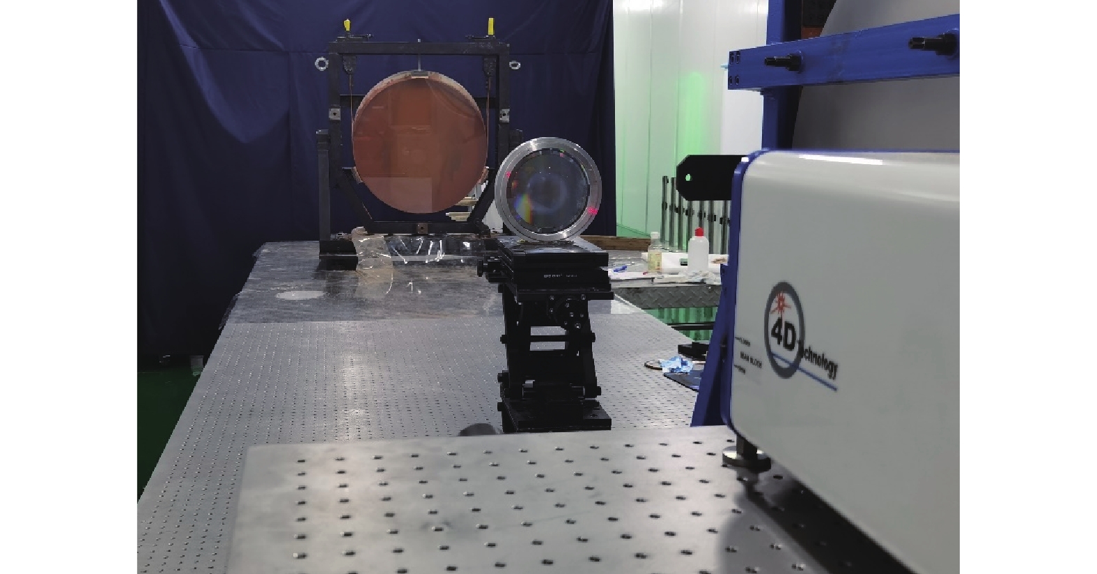
搭建如图8所示光路对非球面进行检测,采用4D干涉仪配4 in F#3.3标准镜。

Figure 8. Optical path of CGH testing
首先将CGH放置于干涉仪焦点后640 mm,此位置粗调CGH位置后切换条纹模式,调整对准区条纹在3根以内,如图9所示,由图可以看出,采用文中方法加工的混合型计算全息图,对准区条纹3级衍射光仍可保证较高的对比度,易于使用者调整。

Figure 9. Refracive fringe in CGH alignment area
然后将被检测反射镜放置于CGH后3170 mm处,调整被检测镜位姿使干涉条纹稀疏,主区域干涉条纹如图10(a)所示,主区域条纹对比度清晰,检测结果如图10(b)所示,该非球面加工精度优于0.02λ。

Figure 10. (a) Fringe in main area (b) Detection results of main area
-
文中针对低反射率材料非球面检测过程条纹对比度低的问题,提出了一种混合型计算全息图的加工方法,该方法通过加工位相型计算全息图保证主检测区域条纹的高对比度,同时,通过加工反射型对准计算全息图保证对准区域条纹的高对比度。尤其是对准区域使用高衍射级次的CGH设计,该方法在条纹对比度上优势明显。针对微晶玻璃材料离轴抛物镜进行了CGH设计,设计残差RMS优于0.003λ,使用文中提出的方法对混合型计算全息图进行加工,并搭建光路对非球面进行检测,主区域和对准区域条纹对比度清晰,检测精度优于0.02λ。实验证明,该方法可以有效提升条纹对比度,有助于低反射率材料面形检测的光路对准。
Testing of aspheric surface with low reflectivity using hybrid type computer-generated hologram (invited)
doi: 10.3788/IRLA20220547
- Received Date: 2022-08-03
- Rev Recd Date: 2022-08-31
- Publish Date: 2022-09-28
-
Key words:
- CGH /
- low reflectivity /
- diffraction efficiency /
- fringe contrast
Abstract: Computer-generated hologram (CGH) is widely used in high-precision off-axis aspheric surface testing. In order to improve the fringe contrast in the testing process of materials with low reflectivity, a hybrid type computer-generated hologram is proposed. The alignment area uses a reflective hologram, the optimal contrast corresponding to the film reflectivity is derived based on diffraction efficiency model, the main area applies phase type CGH to achieve diffraction efficiency improvement, thereby improving the fringe contrast of the detection area. The processing of hybrid hologram is realized by multi-step photo lithography process, and the off-axis aspheric surface of glass-ceramics material is tested using the fabricated CGH. The experimental results show that the hybrid type CGH can obtain clear fringe contrast, and the final detection accuracy is better than 0.02λ(λ=632.8 nm). The proposed hybrid type CGH can be widely used in the testing of aspheric surfaces with low reflectivity material.


 DownLoad: