


-
在航空发动机领域,进气道气流的总温总压是计算发动机净推力和比燃料消耗等指标时的重要参数,是发动机的设计、测试过程中的重要依据。随着航空发动机的发展,进气道工况环境愈发复杂,这就对总温总压传感器的耐温耐压特性和参数检测精度提出了更高的要求[1-3]。
目前,国内外的探针正朝着微型化、高精度、复合式的方向发展[4]。Bonham等[5]设计比较了三种新型滞止罩结构,提高了探针的测量精度,但采用的仍是传统传感器。与传统传感器相比,光纤传感器以其体积小巧、灵敏度高、抗电磁干扰能力强等优点引起了研究人员的广泛关注[6-8]。刘畅等[9]搭建了光纤法珀多通道压力传感系统,对飞机实体模型进行了压力测量试验。中北大学王楠楠[10] 设计了一种基于黑体辐射原理的光纤总温传感器,对传感器及滞止罩进行了仿真分析。周震等[11]提出一种基于光纤光栅的滞止罩式总温探针,进行了风洞试验,获取了总温参数。孙世政等[12]设计了一种基于光纤光栅的流量温度复合传感器,进行了温度和流量测量。到目前为止,用于同时测量总温总压的光纤复合探针鲜有报道。
文中设计了滞止罩式总温总压光纤复合探针,对其进行了不同结构参数下的有限元仿真。然后,制备了FP总压传感器和FBG总温传感器,并将其组装至滞止罩中,实现了探针的制造。最后,搭建了测试系统对其进行测试,并对压力数据进行了解耦,实现了宽温度范围的高精度测量。
-
发动机进气总温总压光纤复合探针结构如图1所示。光纤法珀(Fabry-Perot, F-P)总压传感器和光纤布拉格光栅( Fiber Bragg grating,FBG)总温传感器采取并排式安装的方式安装在滞止罩中。其中,F-P总压传感器进行压力测量,FBG总温传感器既可以进行温度测量,又可以用于FP压力数据的温度解耦。这种总压传感器和总温传感器并排式的设计使压力敏感膜片不易受到上游滞止压力损失的影响,具有良好的频率响应,可以获得较为准确的滞止压力值,同时有助于减小FBG上的热损失,实现对滞止温度的精确采集以及温度解耦,进而实现总温总压精确测量。

Figure 1. Schematic diagram of the internal structure of the total temperature and pressure probe
为了实现发动机进口气流总压总温的测量,必须使运动的气流绝能等熵的滞止到速度为零的状态,又称为气流滞止状态。在气流总温总压测量中,为了减小速度误差,总温总压探针应该有一个接近于1且稳定的恢复系数。恢复系数包括总温恢复系数Ct和总压恢复系数Cp,可以表示为:
式中:Tg为测量有效温度;T为静温;Tt为总温;PT,probe为探头测得的总压;PT为总压;PS为静压。
能够有效提高传感器恢复系数的方法是在传感器的外端设计合理的滞止罩。综合考虑传感器的安装以及对流场的影响,滞止罩直径设计为5 mm。利用有限元法对多组参数(进出口面积比,传感器位置)进行仿真,设计合理的滞止罩。文中引入压力基求解曲线坐标系下的守恒N-S方程,湍流模型选用通过重正规化群理论分析的(SST) k-omega模型,为了提高收敛速率及求解精度,求解方法选择SIMPLEC方案,流体材料选择ideal-gas[13]。不同进出口面积比下的恢复系数如表1所示,可以看出当进出口面积比为4∶1时,恢复特性最好。进出口面积比为4∶1时的仿真结果如图2所示,滞止罩及流场流速在0.49 Ma以内,总温传感器和总压传感器表面速度滞止为0。
Import/export
area ratioFlow rate/Ma Ct Cp 4.5 0.55 0.85 0.91 4 0.49 0.91 0.93 3.5 0.53 0.84 0.88 Table 1. Recovery coefficient of stagnation cover at different inlet and outlet area ratios

Figure 2. (a) Stagnation cover velocity cloud; (b) Total pressure cloud; (c) Total temperature cloud
经验表明[14],总温传感器应具有一定的换热功能,感温单元表面流速为0.1~0.2 Ma时,能实现更加精确的温度测量。由于FBG栅区置于出口气后方时对气流没有滞止效果,故只对栅区中心与出气口中心平行及位于出气口前方的情况下建立计算模型,进行流场模拟。FBG表面速度仿真结果如图3所示,在出气口中心处流速最大,当光栅中心位于出气口前方时,表面流速分布更加均匀,有助于减小由气流引起的机械扰动的误差。

Figure 3. (a) Velocity cloud diagram and distribution of FBG at the center of the outlet; (b) Velocity cloud map and distribution of FBG in front of the outlet 0.5 mm
-
传感器结构如图4所示,由刻蚀的硅敏感膜片、高硼硅玻璃、打孔硅和打孔玻璃四层结构经过三次键合,最后与光纤集成[15]。当压力发生改变时,硅敏感膜片发生形变,F-P腔长发生改变,进而压力信号发生变化,通过干涉谱进行处理获得F-P腔腔长,即可获得传感器所在环境的压力值。

Figure 4. Schematic diagram of total pressure sensor structure
从图4可以看出,当光进入光纤后,首先部分反射,然后透射光在玻璃晶圆端面和硅晶圆的端面之间多次反射。光多次反射回玻璃晶片形成了多光束干涉,干涉光谱由下式确定:
式中:I1和I2分别为入射光和透射光的强度。
根据弹性力学理论,在施加均匀分布的压力下,圆形传感器膜片的中心偏移和灵敏度为:
式中:W为膜片中心偏移量;Y为膜片灵敏度;P为施加在硅敏感膜片上的压力;E为杨氏模量;μ为泊松比;r和h分别为膜片的有效半径和厚度。硅敏感膜片采用晶向N型<100>的单晶硅材料。
总温总压光纤复合探针要求硅总压传感器具有足够小的尺寸。因此,综合考虑传感器的制备工艺,硅膜片的直径设计在1 mm以内。对硅敏感膜片厚度与压力量程和灵敏度的关系进行参数模拟仿真,得到结果如图5所示。
基于小挠度理论,综合考虑工艺水平、解调腔长及灵敏度等,确定总压传感器结构参数如表2所示。

Figure 5. (a) Relationship between pressure range and diaphragm thickness; (b) Relationship between sensitivity and diaphragm thickness
Performance Symbol Value Diaphragm radius/mm r 0.45 Diaphragm thickness/μm h 18 Sensor sensitivity/μm·MPa–1 Y 9.20 Table 2. Structural parameters of the total pressure sensor
-
当气流流入滞止罩后,在FBG表面滞止,动能转换为内能,引起温度的升高。其感受到温度变化,反射谱中心波长产生图6中的漂移,其原理如下式所示:
式中:
$ \Delta {\lambda _B}$ 为光栅中心波长的变化量;$\Delta {n_{{\rm{eff}}}}$ 为纤芯折射率的变化量;$ \Delta \varLambda$ 为光栅栅格周期的变化量。
Figure 6. FBG total temperature sensor spectra
搭建的飞秒激光微加工平台包括飞秒激光器、高精密位移平台和光路系统。利用表3所示参数的飞秒激光脉冲在不剥除涂覆层的情况下,在聚酰亚胺光纤上直写光栅,制备机械性能良好、可靠性高的总温传感器。
Performance Symbol Value Wavelength/nm λ 1030 Frequency/kHz F 200 Pulse-width/fs S 250 Frequency multiplier - 2 Table 3. Femtosecond laser processing parameters
-
搭建的静态环境下光纤总温总压传感器的温压联合测试平台如图7(a)所示,包括光纤F-P总压传感器传感系统、FBG总温传感器传感系统、压力控制系统和温度控制系统。其中,光纤F=P总压传感系统由光纤F-P总压传感器、光纤F-P压力传感器信号解调器、计算机组成;FBG总温传感系统由光纤FBG总温传感器、光栅解调仪、计算机构成。光纤F-P总压传感器与FBG总温传感器均通过密封光纤连接器连接到解调系统。压力控制系统由压力罐、氩气瓶、校准压力传感器和数字压力指示器所构成,压力控制精度为1 kPa。压力罐内的压力由压力控制系统自动控制,通过充放氩气来创造一个恒定压力环境。温度控制系统由加热器、罐内保温装置、温度控制器、校准热电偶和数字温度表所构成,温度控制精度为1 ℃。加热器置于压力罐内,用来制造高温环境。保温装置由多孔透气材料制成,实现该区域内外的压力相等。校准后的热电偶和数字温度表提供温度基准。

Figure 7. Temperature-pressure composite test platform. (a) Test system and principle; (b) Test site
在将制备好的光纤F-P总压传感器与FBG总温传感器并封装到滞止罩后,对总温总压探针各方面的性能进行测试,测试现场如图7(b)所示。对压力参数测试时,首先在常温下将测试炉体设为真空环境,保持60 min,每10 min记录一次F-P腔长,随后将炉体内的压力升至0.25 MPa后,同样保持60 min,每10 min记录一次腔长;然后向炉体内以0.05 MPa的步长将压力从真空增压至0.25 MPa,在每一个压力点保持5 min后采集一次腔长值,达到0.25 MPa的压力之后以同样的步长进行降压,同样在每一个压力点保持5 min,待压力稳定后,记录腔长;在23 ℃、60 ℃、90 ℃、120 ℃和150 ℃下分别进行升压降压实验;最后在常温及150 ℃时进行三次循环升压降压实验,测试结果如图8所示。

Figure 8. (a) Pressure stability test results; (b) Pressure linearity output results; (c) Pressure output results at different temperatures; (d) Pressure repeatability test results
从图8(a)可知,总压传感器在压力保持恒定的条件下,腔长变化量不超过±8 nm,具有良好的稳定性;从图8(b)可知,常温下总压传感器灵敏度为9.01 nm/kPa,与理论设计基本吻合;从图8(c)可以看出,总压传感器在不同温度下每条拟合直线的压力零点不同,这主要是由于法珀腔的热膨胀导致腔长发生温度漂移引起的,而各温度下的灵敏度不同则是由于单晶硅材料的弹性模量随温度升高而降低引起的。从图8(d)可以看出,常温和150 ℃下传感器的重复性良好。
同时,进行常压下总温传感器的温度实验,在测试炉体升温至每个温度点后稳定30 min,记录FBG的中心波长。总温传感器的温度响应曲线如图9所示。可以看出,温度灵敏度约为11.65 nm/℃,测试结果的最大非线性误差为4.04%。这主要是测试炉体中温度场不稳定导致的测试误差引起的,可以通过改进设备进一步降低测试误差。

Figure 9. Temperature response of total temperature sensor
为了降低温度对总压传感器的影响,可以采用总温传感器的输出结果进行温度解耦。将传感器在不同温度下、传感器常压下灵敏度以及腔长与测量得到的FBG中心波长拟合成曲线,如图10(a)和10(b)所示。可以看出,随着中心波长的增大即温度的升高,传感器腔长输出值及灵敏度逐渐增大。
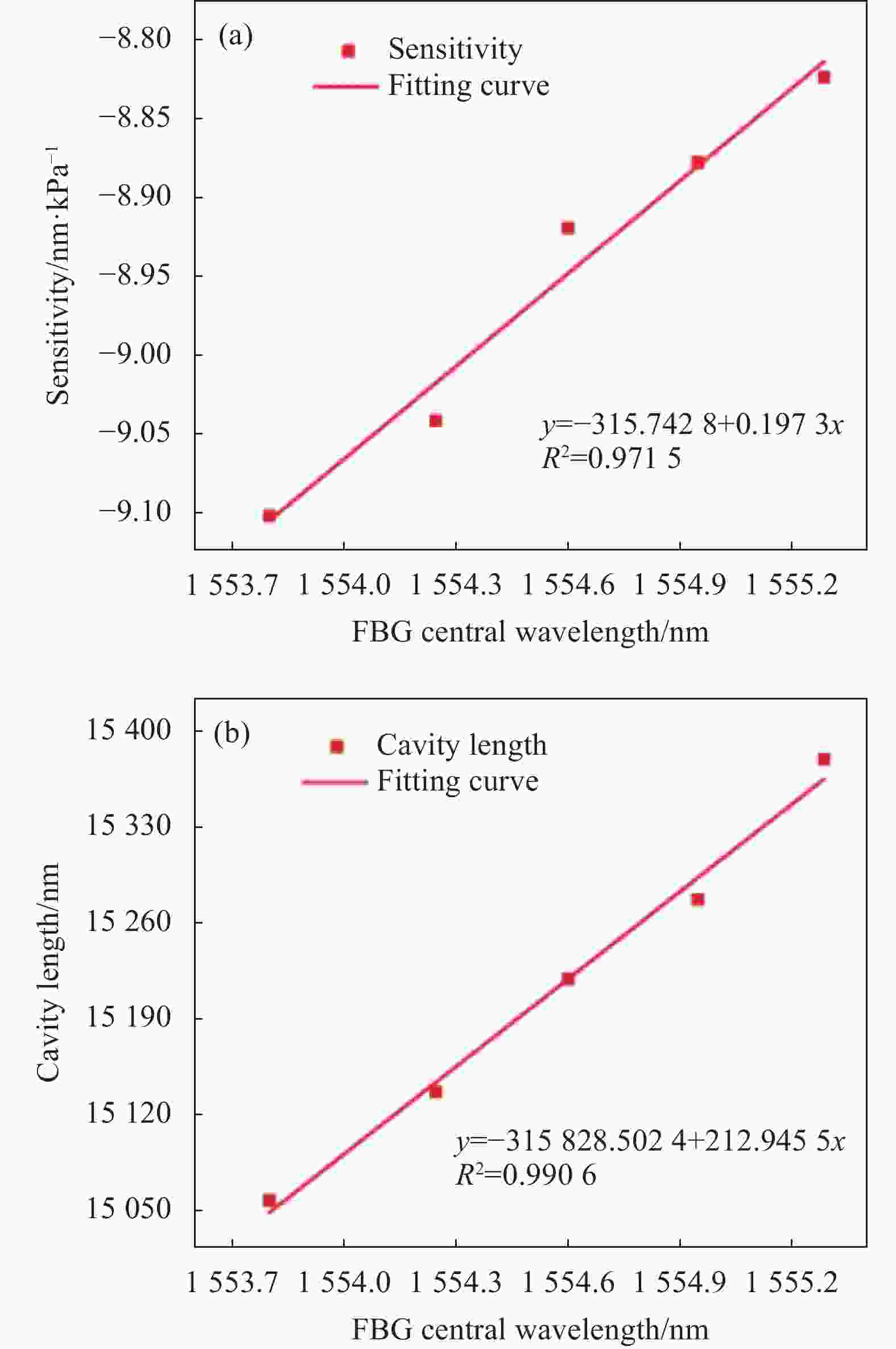
Figure 10. (a) Pressure sensitivity versus FBG center wavelength; (b) Pressure zero output versus FBG center wavelength
根据图10(a)和(b)所示的腔长、灵敏度与FBG测量波长的关系以及图9中FBG中心波长与温度拟合曲线就可以校正总压传感器的零点和灵敏度,从而实现温度解耦。图11为总压传感器在23 ℃、60 ℃、90 ℃、120 ℃和150 ℃解耦后的压力测量结果。可以看出,在0~0.25 MPa压力范围和23~150 ℃温度范围内,温度解耦后的压力最大非线性误差为1.55%。

Figure 11. Pressure measurement results after temperature decoupling
-
文中设计了一种滞止罩式的总温总压光纤复合探针,仿真结果证明所设计的探针0.5 Ma以内时能够测量气流的总温总压。制备的光纤F-P总压传感器非线性度小于0.5%,FBG总温传感器非线性度小于4.04%。同时,通过对压力传感器进行温度解耦,结果表明在0~0.25 MPa和23~150 ℃范围内,最大非线性度误差不超过1.55%,可实现宽温度范围对总压的测量需求。采用光纤传感器作为测量元件设计的探针横截面直径仅为5 mm,通过进一步优化设计还可以将其尺寸做得更小,在对气流产生同等畸变的情况下,使用光纤总温总压探针可以大大提高测量的空间分辨力,充分证明了以光纤传感器测量气流总温总压具有可行性。
Design of a fiber-optic composite probe for engine intake total temperature and pressure (invited)
doi: 10.3788/IRLA20220685
- Received Date: 2022-09-22
- Rev Recd Date: 2022-10-09
- Available Online: 2022-11-02
- Publish Date: 2022-10-28
Fund Project:
National Natural Science Foundation of China(51935011);Key National Science and Technology Projects(J2019-V-0015-0110)
-
Key words:
- total temperature and pressure /
- stagnation cover /
- Fabry-Perot /
- fiber Bragg grating /
- temperature decoupling
Abstract: A stagnation cover type total temperature and pressure fiber-optic composite probe is designed for the demand of total temperature and pressure measurement at the engine inlet. Firstly, the aerodynamic simulation of the probe structure was carried out by using the finite element method, and the influence of the probe structure parameters on the measurement results was analyzed. On this basis, the total temperature and pressure fiber-optic composite probe was fabricated and its working performance was tested by building a static test system. The experimental results show that the total temperature and pressure fiber-optic composite probe can work under the temperature and pressure composite environment of 150 ℃ and 0.25 MPa. The maximum nonlinearity of the total pressure sensor is 0.5% in the range of room temperature - 150 °C, and the maximum nonlinearity of the total temperature sensor is 4.04% in the ambient pressure environment. Finally, the temperature decoupling of the pressure parameters was completed, and the pressure measurement error in the full temperature range did not exceed 1.55%. The designed total temperature and pressure fiber optic composite probe diameter is 5 mm, which effectively reduces the interference of the probe to the flow field.


 DownLoad: