Volume 52 Issue 10
Oct.  2023
Turn off MathJax
Article Contents

Lin Haisheng, Wu Zhibo, Zheng Min, Long Mingliang, Geng Renfang, Yu Rongzong, Zhang Zhongping. Research and application of picosecond accuracy time delay calibration for satellite laser ranging system[J]. Infrared and Laser Engineering, 2023, 52(10): 20230070. doi: 10.3788/IRLA20230070
Citation: Lin Haisheng, Wu Zhibo, Zheng Min, Long Mingliang, Geng Renfang, Yu Rongzong, Zhang Zhongping. Research and application of picosecond accuracy time delay calibration for satellite laser ranging system[J]. Infrared and Laser Engineering, 2023, 52(10): 20230070. doi: 10.3788/IRLA20230070

Research and application of picosecond accuracy time delay calibration for satellite laser ranging system

doi: 10.3788/IRLA20230070
Funds:  National Natural Science Foundation of China (12003056, 11903066); Chinese Academy of Sciences Strategic Leading Science and Technology Project (XDA30030500); Youth Innovation Promotion Association of Chinese Academy of Sciences (2018303); State Grid Jiangsu Electric Power Co., Ltd. Technology Project (J2021203)
  • Received Date: 2023-02-14
  • Rev Recd Date: 2023-04-03
  • Publish Date: 2023-10-24
  •   Objective  Satellite laser ranging (SLR) is a highly accurate space geodesy technology that uses short pulse lasers, optical receivers, onboard reflectors, and event timers to measure the distance between a satellite and the ground, with a measurement accuracy of up to sub-centimeter level. It is widely used in various scientific studies, including the precise geocentric position and motion of ground stations, satellite orbits, Earth's gravity field components and their temporal variations, and Earth's directional parameters. The SLR system calibrates its delay by measuring a ground target at a known distance, which enables calibration accuracy to reach millimeter level. This calibration method is currently used in most SLR stations. With the development of SLR technology, new applications have emerged, such as one-way laser ranging, laser time transfer, interplanetary laser ranging, and multi-station collaborative laser ranging. These applications require accurate one-way delay calibration of the SLR system, which is difficult to obtain by measuring ground targets, limiting the development of these applications. To meet the requirements of laser time transfer at the Chinese Space Station (CSS) and carry out high-precision system transmission and reception delay calibration research, this article focuses on calibrating the one-way delay of the SLR system.   Methods  This paper presents a high-precision method for measuring the transmission and reception delay of SLR. Firstly, the composition delay of the SLR system was comprehensively analyzed, which includes the optical delay generated during laser propagation, the photoelectric conversion delay during photon detection, and the electrical delay of transmitting electrical signals (Fig.1). Secondly, various time delays were measured, such as electrical, optical, and optoelectronic conversion at the Shanghai Astronomical Observatory (SHAO). For this purpose, an event timer A033 with a measurement accuracy of 3 ps, a dead time of 50 ns, a signal generator ETTG-100 with an accuracy of 4 ps, a laser with a 532 nm wavelength, 2 kHz repetition rate, and energy fluctuation of less than 3%, as well as adapters and signal converters are used. And a high measurement accuracy of these delays was achieved, reaching the picosecond level. Finally, the time delay of each segment is combined to calibrate the transmission delay (Fig.4), reception time delay (Fig.5), and ground target distance of the SLR system.   Results and Discussions   The SLR system of SHAO was used as an experimental platform to measure time delays. The cable delay was measured at (107 100 ± 2) ps, the delay of the optical path from the 45° mirror of the transmitting cylinder to the fixed target was measured at (8 563 ± 2) ps, and the delay of the linear detector was measured at (13 444 ± 8) ps. The accuracy of these measurements was at the picosecond level, which meets the required standards. Using these measurement results, the transmission and reception delay were calibrated with calibration results of −4 698 ps and 192 269 ps, respectively. The calibration accuracy was better than 11 ps and 13 ps (Tab.5). This calibration method was then applied to verify the ground target distance deviation, and the difference between the calibration results and the feedback value from the International Laser Ranging Organization was only 11 ps.   Conclusions  In this paper, a novel method for accurately measuring the transmission and reception delay of the satellite laser ranging system is presented. This method is crucial in meeting the requirements of the laser time comparison task at CSS. The method comprehensively considers the delay of the signal transmission cable, optical path, lens, and linear detector, resulting in picosecond calibration of their delay. The calibration of the transmission and reception delay of the SLR system at SHAO was achieved with calibration errors of less than 11 ps and 13 ps, respectively. This method can reduce the systematic deviation of observation stations when applied to the calibration of fixed ground target distance deviation. Moreover, it provides technical support for laser time comparison engineering and a reference for improving the quality of the SLR data.
  • [1] Altamimi Z, Rebischung P, Métivier L, et al. ITRF 2014: A new release of the International Terrestrial Reference Frame modeling nonlinear station motions [J]. Geophysical Research: Solid Earth, 2016, 121(8): 6109-6131. doi:  10.1002/2016JB013098
    [2] Turyshev S G, Farr W, Folkner W M, et al. Advancing tests of relativistic gravity via laser ranging to Phobos [J]. Experimental Astronomy, 2010, 28(2): 209-249. doi:  https://doi.org/10.1007/s10686-010-9199-9
    [3] Meng W, Zhang H, Huang P, et al. Design and experiment of onboard laser time transfer in Chinese Beidou navigation satellites [J]. Advances in Space Research, 2013, 51(6): 951-958. (in Chinese) doi:  10.1016/j.asr.2012.08.007
    [4] Samain E, Weick J, Vrancken P, et al. Time transfer by laser link–the T2L2 experiment on Jason-2 and further experiments [J]. International Journal of Modern Physics D, 2008, 17(7): 1043-1054. doi:  10.1142/S0218271808012681
    [5] Schreiber U, Prochazka I, Lauber P, et al. The European Laser Timing (ELT) experiment on-board ACES[C]//2009 IEEE Inter-national Frequency Control Symposium Joint with the 22nd European Frequency and Time Forum. IEEE, 2009: 594-599.
    [6] Kirchner G, Koidl F, Friederich F, et al. Laser measurements to space debris from Graz SLR station [J]. Advances in Space Research, 2013, 51(1): 21-24. doi:  10.1016/j.asr.2012.08.009
    [7] Schreiber K U, Prochazka I, Lauber P, et al. Ground-based demonstration of the European Laser Timing (ETL) experiment [J]. IEEE Transactions on Ultrasonics, Ferroelectrics, and Frequency Control, 2010, 57(3): 728-737. doi:  10.1109/TUFFC.2010.1471
    [8] Exertier P, Belli A, Samain E, et al. Time and laser ranging: a window of opportunity for geodesy, navigation, and metrology [J]. Journal of Geodesy, 2019, 93: 2389-2404. doi:  10.1007/s00190-018-1173-8
    [9] Samain E, Exertier P, Courde C, et al. Time transfer by laser link: a complete analysis of the uncertainty budget [J]. Metrologia, 2015, 52(2): 423. doi:  10.1088/0026-1394/52/2/423
    [10] Prochazka I, Kodet J, Blazej J, et al. Identification and calibration of one-way delays in satellite laser ranging systems [J]. Advances in Space Research, 2017, 59(10): 2466-2472. doi:  10.1016/j.asr.2017.02.027
    [11] 龙明亮, 张海峰, 邓华荣等. 距离千米级双望远镜的空间碎片激光测距[J]. 光学学报, 2020, 40(02): 192-199. doi:  10.3788/AOS202040.0228002

    Long Mingliang, Zhang Haifeng, Deng Huarong, et al. Laser ranging for space debris using double telescopes with kilometer-level distance [J]. Acta Optica Sinica, 2020, 40(2): 0228002. (in Chinese) doi:  10.3788/AOS202040.0228002
    [12] 耿仁方, 吴志波, 汤凯, 等. 高重复率激光时间比对激光发射时序精确控制[J]. 红外与激光工程, 2021, 50(10): 135-143. doi:  10.3788/IRLA20200473

    Geng Renfang, Wu Zhibo, Tang Kai, et al. Precise control of laser emission epoch in laser time transfer with high repetition rate [J]. Infrared and Laser Engineering, 2021, 50(10): 20200473. (in Chinese) doi:  10.3788/IRLA20200473
    [13] 李德儒. 群时延测量技术[M]. 北京: 电子工业出版社, 1990.
    [14] 尹仲琪, 彭静英, 黄凯冬, 胡勇, 沈世科. 时延测量方法的分析与比较[J]. 电讯技术, 2006(06): 213-216. doi:  10.3969/j.issn.1001-893X.2006.06.052

    Yin Zhongqi, Peng Jingying, Huang Kaidong, et al. Analysis and camparison of selay measuring methods [J]. Telecommu-nication Engineering, 2006(6): 213-216. (in Chinese) doi:  10.3969/j.issn.1001-893X.2006.06.052
    [15] Plumb J. Absolute calibration of a geodetic time transfer system [J]. IEEE Trans Ultrason Ferroelectr Frequency Control, 2005, 52: 1904-1911. doi:  10.1109/TUFFC.2005.1561658
    [16] Wei Haitao, Yu Baoguo, Li Gang, et al. The accurate method for the equipment time-delay and research on testing technology in satellite navigation system [J]. Scientia Sinica: Phys, Mech & Astron, 2010, 40(5): 623-627. doi:  https://doi.org/10.1360/2010-40-5-623
    [17] Artyukh Y, Bespalko V, Boole E. Event timer A033-ET: Current state and typical performance characteristics[C]//Proceedings of the 17th International Workshop on Laser Ranging. Bad Koetzting, Germany, 2011: 398-403.
    [18] 吴志波, 邓华荣, 张海峰, 等. 卫星激光测距系统稳定性分析及提高[J]. 红外与毫米波学报, 2019, 38(04): 479-484+492. doi:  10.11972/j.issn.1001-9014.2019.04.014

    Wu Zhibo, Deng Huarong, Zhang Haifeng, et al. Analysis and improvement on the stability of satellite laser ranging system [J]. Journal of Infrared and Millimeter Waves, 2019, 38(4): 479-484, 492. (in Chinese) doi:  10.11972/j.issn.1001-9014.2019.04.014
    [19] Times Microwave Systems. LRM-240 coax cables datasheet[EB/OL]. [20233-02-08]. https://timesmicrowave.com/documen-tation/lmr-240-coax-cables-datasheet/.
    [20] Eventech Ltd. Test pulse generator with low jitter ETTG-100[EB/OL]. [2023-02-23]. https://eventechsite.com/products/pulse-generator-ettg-100/.
    [21] Kodet J, Prochazka I. Note: Optical trigger device with sub-picosecond timing jitter and stability [J]. Review of Scientific Instruments, 2012, 83(3): 036101. doi:  10.1063/1.3665919
    [22] Prochazka I, Blazej J, Kodet J. Measurement of the optical to electrical detection delay in the detector for ground-to-space laser time transfer [J]. Metrologia, 2011, 48: L13-L16. doi:  10.1088/0026-1394/48/3/L01
    [23] 秦思, 吴志波, 张海峰, 张忠萍. 高精度事件计时器及其在卫星激光测距应用[J]. 激光与红外, 2019, 49(04): 419-423. doi:  10.3969/j.issn.1001-5078.2019.04.005

    Qin Si, Wu Zhibo, Zhang Haifeng, et al. High precise event timer and its application to satellite laser ranging [J]. Laser & Infrared, 2019, 49(4): 419-423. (in Chinese) doi:  10.3969/j.issn.1001-5078.2019.04.005
    [24] Meng W D. Research on laser time transfer and payload technology for Chinese space station[D]. Shanghai: East China Normal University, 2021. (in Chinese)
    [25] Geoscience Hitotsubashi. Multi-satellite bias analysis report v2 for worldwide satellite laser ranging stations[DB/OL]. [2023-02-10]. https://geo.science.hit-u.ac.jp/slr/bias/.
  • 加载中
通讯作者: 陈斌, bchen63@163.com
  • 1. 

    沈阳化工大学材料科学与工程学院 沈阳 110142

  1. 本站搜索
  2. 百度学术搜索
  3. 万方数据库搜索
  4. CNKI搜索

Figures(11)  / Tables(5)

Article Metrics

Article views(107) PDF downloads(49) Cited by()

Related
Proportional views

Research and application of picosecond accuracy time delay calibration for satellite laser ranging system

doi: 10.3788/IRLA20230070
  • 1. School of Mechatronic Engineering and Automation, Shanghai University, Shanghai 200444, China
  • 2. Shanghai Astronomical Observatory, Chinese Academy of Sciences, Shanghai 200030, China
  • 3. Key Laboratory of Space Object and Debris Observation, Chinese Academy of Sciences, Nanjing 210008, China
  • 4. University of Chinese Academy of Sciences, Beijing 100049, China
  • 5. School of Materials Science and Engineering, Shanghai University, Shanghai 200444, China
Fund Project:  National Natural Science Foundation of China (12003056, 11903066); Chinese Academy of Sciences Strategic Leading Science and Technology Project (XDA30030500); Youth Innovation Promotion Association of Chinese Academy of Sciences (2018303); State Grid Jiangsu Electric Power Co., Ltd. Technology Project (J2021203)

Abstract:   Objective  Satellite laser ranging (SLR) is a highly accurate space geodesy technology that uses short pulse lasers, optical receivers, onboard reflectors, and event timers to measure the distance between a satellite and the ground, with a measurement accuracy of up to sub-centimeter level. It is widely used in various scientific studies, including the precise geocentric position and motion of ground stations, satellite orbits, Earth's gravity field components and their temporal variations, and Earth's directional parameters. The SLR system calibrates its delay by measuring a ground target at a known distance, which enables calibration accuracy to reach millimeter level. This calibration method is currently used in most SLR stations. With the development of SLR technology, new applications have emerged, such as one-way laser ranging, laser time transfer, interplanetary laser ranging, and multi-station collaborative laser ranging. These applications require accurate one-way delay calibration of the SLR system, which is difficult to obtain by measuring ground targets, limiting the development of these applications. To meet the requirements of laser time transfer at the Chinese Space Station (CSS) and carry out high-precision system transmission and reception delay calibration research, this article focuses on calibrating the one-way delay of the SLR system.   Methods  This paper presents a high-precision method for measuring the transmission and reception delay of SLR. Firstly, the composition delay of the SLR system was comprehensively analyzed, which includes the optical delay generated during laser propagation, the photoelectric conversion delay during photon detection, and the electrical delay of transmitting electrical signals (Fig.1). Secondly, various time delays were measured, such as electrical, optical, and optoelectronic conversion at the Shanghai Astronomical Observatory (SHAO). For this purpose, an event timer A033 with a measurement accuracy of 3 ps, a dead time of 50 ns, a signal generator ETTG-100 with an accuracy of 4 ps, a laser with a 532 nm wavelength, 2 kHz repetition rate, and energy fluctuation of less than 3%, as well as adapters and signal converters are used. And a high measurement accuracy of these delays was achieved, reaching the picosecond level. Finally, the time delay of each segment is combined to calibrate the transmission delay (Fig.4), reception time delay (Fig.5), and ground target distance of the SLR system.   Results and Discussions   The SLR system of SHAO was used as an experimental platform to measure time delays. The cable delay was measured at (107 100 ± 2) ps, the delay of the optical path from the 45° mirror of the transmitting cylinder to the fixed target was measured at (8 563 ± 2) ps, and the delay of the linear detector was measured at (13 444 ± 8) ps. The accuracy of these measurements was at the picosecond level, which meets the required standards. Using these measurement results, the transmission and reception delay were calibrated with calibration results of −4 698 ps and 192 269 ps, respectively. The calibration accuracy was better than 11 ps and 13 ps (Tab.5). This calibration method was then applied to verify the ground target distance deviation, and the difference between the calibration results and the feedback value from the International Laser Ranging Organization was only 11 ps.   Conclusions  In this paper, a novel method for accurately measuring the transmission and reception delay of the satellite laser ranging system is presented. This method is crucial in meeting the requirements of the laser time comparison task at CSS. The method comprehensively considers the delay of the signal transmission cable, optical path, lens, and linear detector, resulting in picosecond calibration of their delay. The calibration of the transmission and reception delay of the SLR system at SHAO was achieved with calibration errors of less than 11 ps and 13 ps, respectively. This method can reduce the systematic deviation of observation stations when applied to the calibration of fixed ground target distance deviation. Moreover, it provides technical support for laser time comparison engineering and a reference for improving the quality of the SLR data.

    • 卫星激光测距(Satellite Laser Ranging, SLR)是目前准确度最高的空间大地测量技术之一,通过记录激光脉冲往返测站到卫星的时间,精确获得地卫之间的距离,广泛应用于卫星精密定轨、地球自转参数求解和台站坐标确定[1]等领域。随着SLR技术的发展,其应用领域逐渐多元化,一些新的应用逐渐出现,如激光时间比对、多台站协同测距和行星际激光测距等[2-6],同时这也带来了新的挑战。

      SLR系统获得的原始数据是激光从主波探头产生的起始脉冲到回波探测器获得的关门信号之间的时间间隔,而实际应用需要将地面的时刻归算到望远镜相位中心(望远镜水平轴和竖直轴交点)。由于原始主波和回波时刻与激光脉冲经过望远镜相位中心的时刻不一致,需要在原始测量数据中扣除耦合收发时延的系统偏差量。虽然激光测距系统中存在着复杂的光学、电学和光电转换等系统时延,但是根据卫星激光测距的原理公式可知,可以将其作为一个整体考虑,一般通过测量已知距离的靶目标将耦合收发时延的系统误差扣除,可以实现毫米量级的标定。然而,在激光时间比对中,需要将系统发射和接收时延单独标校[7],传统固定靶目标测量时延标定方法难以适用。在中国空间站和国际空间站中,都将搭载激光时频传递载荷开展星地激光时间比对,预计将实现25 ps的准确度[8],用于开展基础物理参数测定、爱因斯坦广义相对论检验和微波链路标定等研究,该指标的实现高度依赖于系统单向时延的标定性能。因此,需要开展单向收发时延分离标定的研究,服务于未来激光时间比对和单向激光测距等应用研究需求。

      2015年,Samain等人[9]对SLR系统的单向时延不确定度进行评估,综合线性探测器、信号传输线缆等各项的不确定度,得到发射链路的不确定度为34 ps;2017年,Prochazka等人[10]依托国际空间站激光时间比对任务需求,利用自研的时延校准装置对SLR系统的发射和接收时延进行标定,标定精度优于20 ps;2020年,龙明亮等人[11]对SLR系统的发射和接收时延进行测量,测得的两个单向时延与地面靶目标测量的双向总时延相比仅差400 ps,并将测得的单向时延成功应用于相距千米的双望远镜空间碎片测距。由于SLR系统具有差异性或精度不足,上述测试方法很难直接适用。

      为此,文中结合中国空间站激光时间比对的任务需求,开展高准确度的系统收发时延分离标定研究。分析了SLR系统和激光时间比对系统时延的组成,提出了电学、光学和光电转换等时延的高精度测量方法,并开展相应的时延标定。最后,根据测量结果,分析了时延标定的影响因素,估计了发射和接收时延标定的准确度,将该方法应用于地靶距离偏差的校验,验证了该方法的可行性。

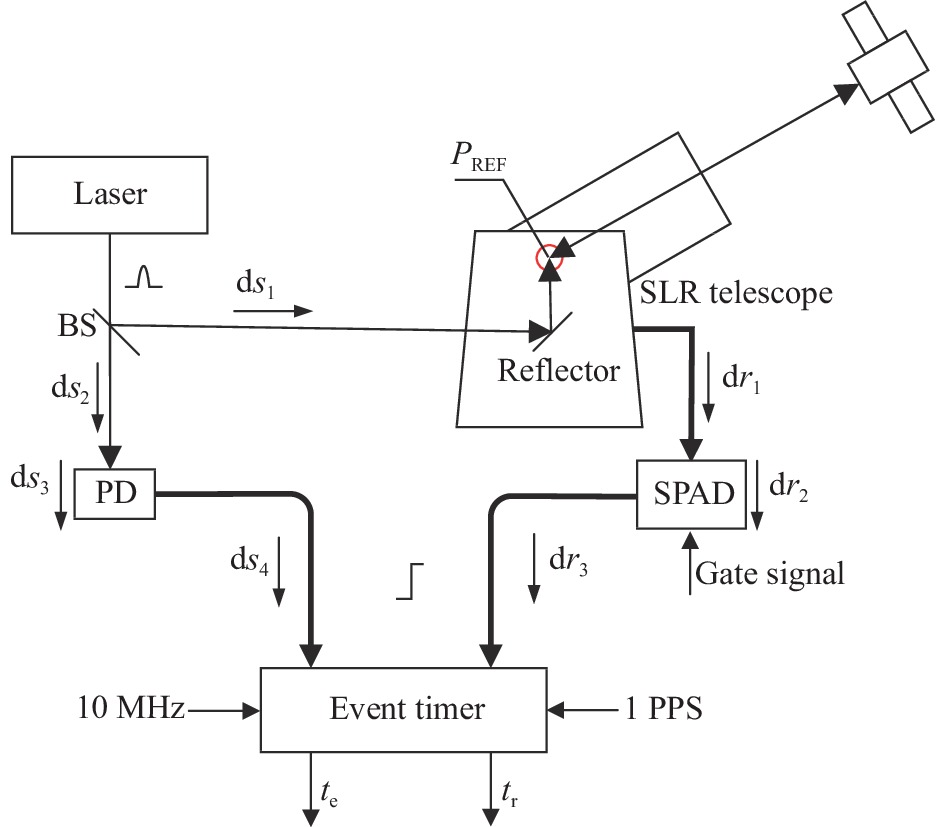
    • SLR系统时延分布如图1所示(图中望远镜取侧视图),激光器产生脉冲激光,经过分光镜BS,少量透过光由线性探测器PD接收,经过光电转换输出电信号,由线缆传递到事件计时器,记录为激光发射时刻值$ {t_e} $。分光镜反射大部分激光,经过数个45°镜后从望远镜发射镜筒发射到卫星,卫星上的角反射器反射部分激光,返回的光信号由望远镜接收端接收,经过光谱滤波处理后由单光子探测器将光信号转换成电信号,信号经传输线缆传递,由事件计时器记录为回波时刻${t_r}$。计算机终端对事件计时器记录的双通道时刻值进行配对和剔点,最后得到包含系统时延量的原始测星数据。

      Figure 1.  Composition and time delay distribution of satellite laser ranging system

      原始激光测距数据中包含耦合收发时延的系统偏差量,需要将测距数据归算到望远镜相位中心,才能获得真实的地卫距离。根据卫星激光测距原理,包含发射和接收时延的激光测距公式可表示为:

      式中:${\rm{ d}}{s_1} $为BS反射面到望远镜相位中心的光路时延;$ {\rm{d}}{s_2} $为BS中的光路时延与BS到PD探测表面间的光路时延之和;$ {\rm{d}}{s_3} $为PD的内部时延;$ {\rm{d}}{s_4} $为从PD的信号输出端到事件计时器端的电信号时延;$ {\rm{d}}{r_1} $为望远镜相位中心到SPAD探测表面的光路时延;$ {\rm{d}}{r_2} $为SPAD的内部时延;$ {\rm{d}}{r_3} $为从SPAD信号输出端到事件计时器端的电信号时延;$ \varepsilon $为链路误差时延。$ {\rm{d}}{s_4} + {\rm{d}}{s_3} + {\rm{d}}{s_2} - {\rm{d}}{s_1} $可统称为系统的发射时延,记为${\delta _e}$;$ {\rm{d}}{r_3} + {\rm{d}}{r_2} + {\rm{d}}{r_1} $可统称为系统的接收时延,记为${\delta _r}$。在SLR系统中,发射时延和接收时延可作为一个整体考虑,通过测量已知距离的固定靶目标获得耦合发射和接收时延的系统偏差量。固定地靶测量原理如图2所示(图中望远镜取俯视图),地靶到相位中心EF的距离为$m$,地靶中两个反射面的距离为$d$,激光经过发射链路到达E点后经发射镜筒到达固定地靶,由固定地靶上的两个反射面HI将光信号传递回望远镜接收镜筒,经过F点后进入接收链路。事件计时器记录的主波和回波时刻分别记录为${t_1}$和${t_2}$,则系统的时延$ {\delta _r} - {\delta _e} $可表示为$ \left( {{t_2} - {t_1}} \right) - {{\left( {2 m + d} \right)} \mathord{\left/ {\vphantom {{\left( {2 m + d} \right)} c}} \right. } c} $。通过测量已知靶目标,可以将耦合收发时延的系统误差整体扣除,该方法已被广泛应用于SLR系统时延标校。以中国科学院上海天文台为例,靶目标测量精度约为6~7 mm[12]

      Figure 2.  Schematic diagram of ground target measurement

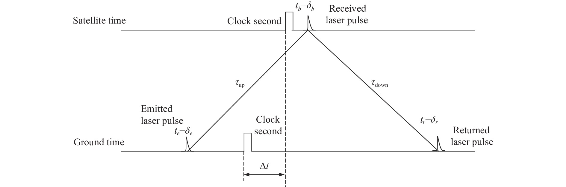
    • 星地激光时间比对链路主要由地面SLR系统和星载激光时间比对系统组成,其原理如图3所示。地面激光测距站在地面钟的$ {t_e} $时刻向卫星发射激光,卫星上的单光子探测器在$ {t_b} $时刻记录探测到的激光脉冲信号,并且激光脉冲经星上反射器返回地面,在地面钟的${t_r}$时刻记录为激光脉冲回波信号。基于同一周期的三个时刻值,并进行相应的系统及链路误差的改正,即可获得地面和星上的钟差值。

      Figure 3.  Schematic diagram of satellite-ground laser time transfer

      根据激光时间比对的原理,考虑系统误差的原理公式[12]可表示为:

      式中:${\delta _r}$为接收时延;${\delta _e}$为发射时延;${\delta _b}$为星上载荷的内部时延(文中不考虑该时延);$\varepsilon $为链路的误差改正。根据公式(2)可知,地面发射和接收时延的标定准确度将直接影响激光时间比对的最终性能。由于SLR系统测量固定靶目标获取的发射和接收时延量关系为${\delta _r} - {\delta _e}$,而激光时间比对中需要改正的时延量为${\delta _r} + {\delta _e}$,因此,测量固定靶目标获取系统时延量的方式不适用于激光时间比对领域。因此,文中开展了发射和接收时延分离标校的方法,以满足未来激光时间比对的应用需求。

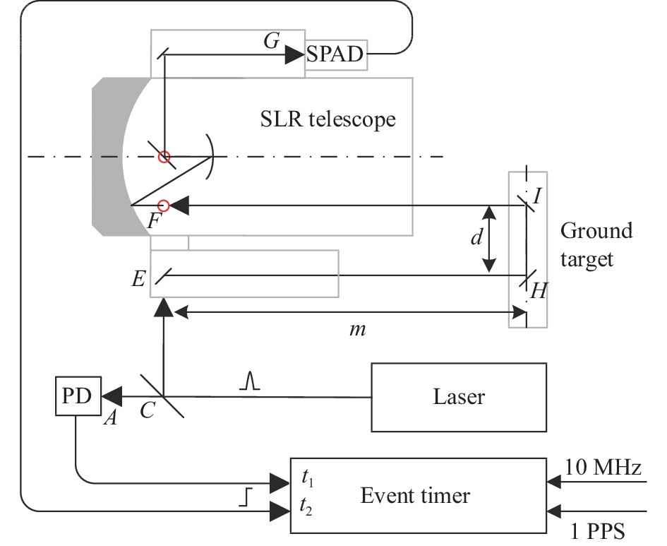
    • 将发射时刻(${t_e}$)修正到望远镜E点的时延量,即SLR系统的发射时延,由光路时延ACCE(${\rm{d}}{s_1}$和${\rm{d}}{s_2}$)、线性探测器PD时延(${\rm{d}}{s_3}$)和线缆${l_1}$时延($ {\rm{d}}{s_4} $)三部分时延组成,详细的示意图如图4所示。由于CE段的光路较为复杂,单独对其测量比较困难且误差较大,文中采用了整体标定发射时延的方法,利用线性探测器PD2E点测量发射时延可以简化测量方式并获得高精度的测量值。使用已知时延的线性探测器PD2和线缆${l_3}$ 在E点处与发射链路组成发射时延标定回路,激光一方面经过发射链路在事件计时器标记时刻${t_e}$,另一方面经过光路CE由线性探测器PD2接收,输出信号经过线缆${l_3}$,在事件计时器标记时刻${t_{rpd2}}$。

      Figure 4.  Schematic diagram of transmission delay measurement

      对两个标记的时刻差值进行相应的补偿之后得到发射时延,具体如公式(3)所示:

      式中:${t_{rpd2}}$和${t_e}$为事件计时器响应两个线性探测器输出信号后记录的时刻值;${t_{epd2}}$为光信号从E点到线性探测器PD2光敏元件表面的距离的时延,该距离较短,测量精度好于1 mm;${t_{pd2}}$为线性探测器PD2的时延;${t_{l3}}$为信号在线缆${l_3}$中的传输时延;${t_{others}}$为调整信号正负和线缆连接方式而加入的信号转换器时延和转接头时延之和。

      时间间隔${t_{rpd2}} - {t_e}$需要大于事件计时器的死时间,在上述过程中,CE光路的时延大于CA光路的时延,两个线性探测器的时延相近,因此需要线缆${l_3}$的时延大于线缆${l_1}$的时延与事件计时器死时间之和,其中线缆${l_1}$为短线,时延小于25 ns。

    • 将接收时刻(${t_r}$)修正到望远镜F点的时延量,即SLR系统的接收时延,由光路时延FG(${\rm{d}}{r_1}$)、单光子探测器SPAD时延(${\rm{d}}{r_2}$)和线缆${l_2}$时延(${\rm{d}}{r_3}$)三部分时延组成,具体如图5所示。文中采用整体标定接收时延的方法,利用线性探测器PD2B点测量接收时延可以简化测量方式获得高精度的测量值。使用已知时延的线性探测器PD2和线缆${l_3}$ 在B点处与接收链路组成发射时延标定回路。激光到达H处的楔形镜后分成两路,一路反射经过HIIF进入接收链路,在事件计时器处标记时刻$ {t_r} $;另一路折射透过楔形镜,经过HB被线性探测器PD2接收输出电信号,经过线缆${l_3}$后在事件计时器处标记时刻$ {t_{spd2}} $。

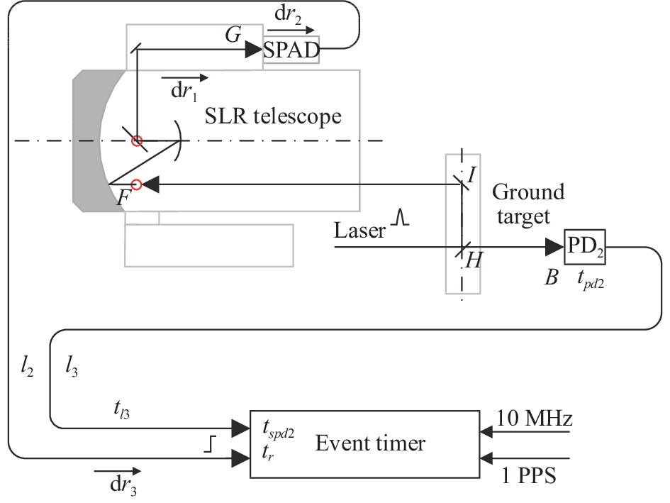
      Figure 5.  Schematic diagram of reception delay measurement

      对两个标记的时刻值作差,并对线缆${l_3}$、线性探测器、光路HBHIIF和楔形镜片折射的时延进行补偿之后得到接收时延,具体如公式(4)所示:

      式中:$ {t_r} $和$ {t_{spd2}} $为事件计时器分别响应单光子探测器和线性探测器输出信号后记录的时刻值;$ {t_H} $为H点处光信号在楔形镜中的时延;$ {t_{HB}} $为H点处楔形镜后表面到线性探测器PD2光敏元件表面的距离引起的时延;$ {t_{IH}} $和$ {t_{IF}} $为光路时延。

      时间间隔$ {t_r} - {t_{spd2}} $要大于事件计时器的死时间,在上述过程中,光路HIIFFG的时延大于光路HB的时延,单光子探测器SPAD的时延大于线性探测器的时延,这两部分的时延差的总和大于10 ns,因此线缆${l_2}$和线缆${l_3}$的时延差要大于$ ({t_{deadtime}} - 10) $ ns,其中线缆${l_2}$为长线缆,时延大于150 ns。

    • 常用的时延测量方法有矢量网络分析仪法、示波器法、 时间间隔测量仪法和相位计法[13-15]。矢量网络分析仪法可测量线性网络的相时延和群时延;相位计法可以测量连续波信号通过被测件时的相时延和群时延;示波器法和时间间隔测量仪法可以测量连续波、脉冲信号通过被测件时的相时延和脉冲传输时延[16]

      如今,随着计时器技术的提升,时间间隔测量仪法的测量精度得到了提升。事件计时器对达到响应阈值的脉冲信号进行时刻标记,时刻值记录分为粗计时和精计时两部分,响应速度快,时刻记录精度能达到皮秒量级,被广泛应用于SLR台站。目前,上海台SLR系统使用了拉脱维亚生产的A033事件计时器。该计时器的测量精度为3 ps,计时死时间为50 ns,对信号的下降沿响应[17-18]

    • 线缆时延的标定采用高精度高稳定的信号发生器配合功率分配器和事件计时器完成,具体如图6所示。信号源的输出信号经功率分配器分成两路频率、幅值和脉宽相同的信号,两路输出信号分别由两根线缆传递到事件计时器的AB通道,分别标记A路信号的到达时刻和B路信号的到达时刻,两个时刻的时刻差即为两条线缆的长度差对应的时延。信号源和事件计时器均采用同源的1 PPS信号和10 MHz信号作为同步基准。

      Figure 6.  Schematic diagram of cable delay measurement

      实验研究表明,事件计时器等设备预热不充分会导致在长时间工作前后的测量偏差较大[18]。A033事件计时器需要1 h的预热时间[17],实验在设备启动1 h后开始。线缆时延的标定采用二次测量的方式,分别测量线缆${l_4}$ 和${l_5}$的时延差,记为$ \Delta {T_{l54}} $,测量线缆${l_4}$、${l_5}$和${l_3}$的时延差,记为$ \Delta {T_{l354}} $。得到线缆${l_3}$的时延,如公式(5)所示:

      在SLR系统中信号线缆受温度和望远镜转动的影响会发生拉伸和扭转,影响信号传输性能,研究测试表明扭转引起的电信号传输时延变化高达53 ps[18]。在文中,为了克服温度变化和线缆扭转的影响,综合考虑后选用低温漂的高稳相柔性同轴线缆,LMR-240。该型号线缆的参数如表1、表2所示[19]

      ItemMaterialUnit/in (mm)
      Inner conductorSolid BC0.056 (1.42)
      DielectricFoam PE0.150 (3.81)
      Outer conductorAluminum tape0.155 (3.94)
      Overall braidTinned copper0.178 (4.52)

      Table 1.  Material parameter of cable LMR-240

      Performance propertyUS (metric)Unit
      Velocity of propagation84%
      Dielectric constant1.42NA
      Time delay1.21 (3.97)ns/ft (ns/m)
      Impedance50Ω·m
      Capacitance24.2 (79.4)pF/ft (pF/m)
      Inductance0.06 (0.2)µH/ft (µH/m)
      Shielding effectiveness>90dB
      Inner conductor DC resistance3.2 (10.5)Ohms/1000 ft (/km)
      Outer conductor DC resistance3.89 (12.8)Ohms/1000 ft (/km)
      Voltage withstand1500V, DC
      Peak power5.6kW
      Operating temperature range−40/85

      Table 2.  Electrical parameter of cable LMR-240

      采用模拟信号对线缆时延进行标定,信号源输出信号的能力会直接影响标定的准确度,高稳定高精度的信号源是实现高准确度线缆时延标定的关键。文中采用信号发生器ETTG-100[20],其输出信号的脉冲前沿到达触发电平时刻的不确定度为4 ps。测试电信号为频率2 kHz、幅值−2 V的脉冲信号。功率分配器为两路带宽射频微波同轴功分器ZFSC-2-1-S+,可以在−55~100 ℃正常工作。使用时延为57 ps的SMA转BNC的转接头将两条线缆相连。测量前,将待测线缆平铺、静置,充分释放应力,并在室温下标定时延。两次测量均值如图7所示,图中数据精确到ps后一位,该位为统计位,意义不大,可以舍去。由公式(5)可知,线缆时延为(107100±2) ps,满足实验过程中计时器死时间的需求。

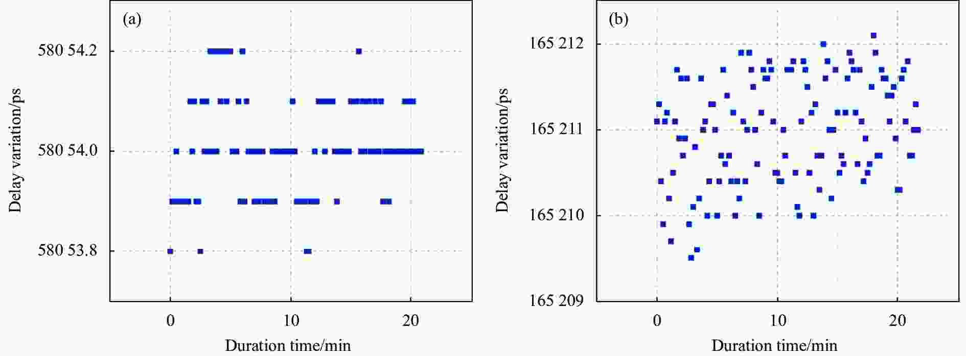
      Figure 7.  (a) Delay variation of the reference cable; (b) Delay variation after adding the the cable to be tested

    • 测量光路时延的方法主要有长度测量和探测器测量两种。发射接收时延标定中需要测量的光路有EHHIIF三段。其中,HI段距离较短可以采用长度测量的方式,EH段采用探测器测量的方式,IF段从EH段经换算得到。

      图8所示,测量EH光路的时延,在E点附近放置线性探测器PD2,与系统的线性探测器PD配合,测得时刻差值$ \Delta {t_{Epd2}} $ ;将PD2放在B点附近测得时刻差值$ \Delta {t_{Bpd2}} $。在这段光程中,存在两个物镜和一个楔形镜片HH’,光在镜片中的时延与镜片的折射率相关,镜片的参数如表3所示。

      Figure 8.  Schematic diagram of optical delay measurement

      ItemMaterialRefractive indexOptical length/mmOptical delay/ps
      Objective lens1H-ZF21.68030.22169
      Objective lens2H-K9L1.51930.42154
      Wedge lens HHH-K9L1.51913.769

      Table 3.  Lens parameter

      可测得EH光路时延如公式(6)所示:

      式中:${t_{H' B}}$为楔形镜后表面到线性探测器光敏元件的距离对应的时延;$ {t_{epd2}} $为线性探测器在E处时E点到线性探测器光敏元件表面的距离;$ {t_H} $为光在楔形镜中的时延。

      通过该方法测EH段光路时延如图9所示,由公式(6)可得,EH段时延为(8563±2) ps,扣除光路中的两个物镜的时延可得IF光路时延为(8442±2) ps。

      此外,在文中标尺测量的光路中,最大的长度小于600 mm,考虑简化的光速(0.3 mm/ps)与空气折射后的光速(0.299 705 543 4 mm/ps)计算的光路时延差小于2 ps,在文中的误差范围以内。因此,为方便计算,文中采用简化的光速计算这部分光路的时延。

      Figure 9.  (a) Delay variation at point E; (b) Delay variation at point B

    • 线性探测器主要用于记录激光发射时刻,可在低能量多光子的情况下正常工作。在一定程度上,随着激光能量的增强,线性探测器的输出波形幅值和脉宽会增大。当入射激光能量达到一定强度后,线性探测器输出的波形达到饱和状态,此时的脉冲前沿较为稳定,适合在稳定性要求比较高的情况下使用。

      目前尚无快速简便的方法能够直接测量线性探测器的时延,但由于其结构简单,部件较少,因此可以较为准确地估计其内部的时延。线性探测器的时延主要由快速光电管、光电转换电路和放大电路三部分组成。

      在实际应用中,线性探测器整体的时延还会受到激光脉宽的影响,表现为对激光脉冲前沿上升时间敏感。线性探测器的响应与激光脉冲的半高宽有关,若激光脉冲的形状接近高斯,则存在修正值${t_{pw}}$:

      式中:FWHM为激光脉冲的半高宽。

      为了便于测试,文中采用一款已严格标定时延的线性探测器,相关参数如表4所示。该探测器有两个输出端口,端口1的时延标定为(211±7) ps[21-22],但驱动能力不足以使A033事件计时器响应。为此,测试时使用驱动能力更强的端口2。两个输出端口间的时延,采用性能与A033相当的事件计时器(ETCS)[23]测量。在室温下,固定设备位置,控制入射光强度相同,使用同一根信号传输线缆,测得两个端口间的时延差为13223 ps。考虑实验所用的激光脉宽为19 ps,结合测量误差,得到端口2的时延为(13444±8) ps。

      ItemParameter
      Detection diodeLinear photodiode on Si
      Active area100 µm in diameter
      Output signals amplitude/V> +2.5
      Operating temperature/℃−50-+40

      Table 4.  Linear detector related parameters

    • 基于中国科学院上海天文台卫星激光测距站的SLR系统,按照上述的标定方案开展了系统发射和接收时延的分离标定。所用的激光器稳定产生2 kHz的短脉冲光信号,激光波长为532 nm,能量波动小于3%,在文中的测量模式下激光脉冲信号的波动影响可以忽略。采用中国科学院上海天文台自研的距离门控电路板,稳定地向激光器发送点火信号,同时给单光子探测器发送门控信号。事件计时器和距离门控板由同源的1 PPS钟信号和10 MHz信号进行时间同步。所用的钟源稳定度为10−12量级,对于小于1 µs的测量结果,钟源带来的影响小于10−18 s,可以忽略。线性探测器的输出信号为正信号,而事件计时器的响应信号为负信号,使用一个时间抖动为2 ps的信号转换器进行电平转换,该转换器的时延为(1254±4) ps。

      通过上述方法对SLR系统的发射时延进行测量,分组采数,每组持续时间10 s,每组数据采用2.2σ进行剔点作均值[10],单次测量精度9 ps,连续进行20 min的数据采集,得到的均值分布如图9(a)所示。由发射时延测量回路测得的测量值为(117451±1) ps。按照公式(3)可得,发射时延均值为−4698 ps。

      测量接收时延,控制信号回波率小于10%,使探测器稳定工作在单光子量级[24],分组采数,每组持续时间26 s,采用2.2σ进行剔点作均值,单次测量精度15 ps,连续进行30 min的数据采集,得到均值分布如图10所示,事件计时器双通道的测量差值为(80287±2) ps。按照公式(4)可得,接收时延均值为192269 ps。

      Figure 10.  Delay variation of reception delay

      此外,在SLR测量卫星的原始数据中存在发射镜筒中的物镜时延,利用固定靶目标进行系统时延校正时,参与校正的系统时延值需要包括物镜时延。因此,只在测得的靶目标均值中扣除靶目标到望远镜相位中心的光路时延,即(2×IF + HI),结合文中对光路的测量结果,该值为(18851±7) ps。所有时延测量结果如表5所示。

      No.ItemTime delay/psNote
      1Cable l3(107100±2)LMR-240, 25 m
      2Linear detector outlet1(211±7)Analog signal outlet
      3Linear detector outlet2(13444±7)Square signal outlet
      4SMA-BNC Adapter(57±3)Box-box
      5Signal convertor 1(1254±4)ITR-1, 50 Ω
      6Wedge lens(69±3)H-K9L, optical 13.7 mm
      7Objective lens1(169±3)H-ZF2, thickness of center 30.22 mm
      8Objective lens2(154±3)H-K9L, thickness of center 30.42 mm
      9Optical path EH(8563±2)E-PD: 71 mm
      10Optical path HI(1967±3)590 mm
      11Optical path IF(8442±2)Optical path without two objective lens
      12Optical path HB(410±3)123 mm
      13Transmission delay−4 698-
      14Reception delay192 269-
      15Ground target to phase center(18 851±5)IF+HI

      Table 5.  Time delay measurement result

    • 在统计学上,由于变量含有误差,而使函数受其影响也含有误差。描述两者误差间关系的定律称为误差传播定律。对于和差函数$ Z = {X_1} \pm {X_2} \pm \cdots \pm {X_n} $且$ {X_1} $、$ {X_2} $、···、$ {X_n} $独立,$ Z $的误差等于n个变量的误差平方和的平方根值,即:

    • 在发射时延测量过程中,受到光路、线性探测器、线缆、激光器能量波动和时钟源抖动等的误差影响。此外,在线缆接口和线性探测器输出信号与事件计时器响应条件不匹配的情况下,还要考虑转接头与信号转换器带来的误差影响。具体表现在以下方面:

      1) E点处镜面到线性探测器PD2的距离测量误差为3 ps;

      2) 线性探测器方波信号输出口时延估计误差为8 ps;

      3) 信号传输线缆时延测量误差为2 ps;

      4) 接口转换头时延测量误差为3 ps;

      5) 信号转换器实验测量误差为4 ps;

      6) 测量均值误差为1 ps。

      根据误差传播定律,若信号能被正确响应,可以不考虑4)、5)的误差,则发射时延的误差将小于9 ps。在文中的实验条件下,标定的发射时延误差小于11 ps。

    • 接收时延测量工具与发射时延一致,但是具有更复杂的测量回路。因此,相比于发射时延标定,接收时延的标定还需要考虑光路IFHIHB以及楔形镜片的误差影响,具体表现在以下方面:

      1) IF光路时延测量误差为5 ps;

      2) HI光路时延测量误差为3 ps;

      3) 楔形镜片HH’时延测量误差为3 ps;

      4) 楔形镜片后表面到线性探测器的距离HB的测量误差为3 ps;

      5) 线性探测器方波信号输出口时延估计误差为8 ps;

      6) 信号传输线缆时延测量误差为2 ps;

      7) 接口转换头时延测量误差为3 ps;

      8) 信号转换器实验测量误差为4 ps;

      9) 测量均值误差为3 ps;

      其中,由于接收时延用到单光子探测器,测量精度相对于发射时延会略差一些,因此,9)的测量均值误差与发射时延的6)相比会更大。若信号能被正确响应,可以不考虑7)、8)的误差,则根据误差传播定律,接收时延的误差将小于12 ps。在文中的实验条件下,标定的接收时延误差小于13 ps。

    • 应用文中提出的方法得到的发射和接收时延误差分别小于11 ps和13 ps,按照误差传播定律可得整体系统时延误差小于20 ps,满足激光时间比对25 ps准确度的要求。时延标定方法能够满足激光时间比对中对系统时延的标校需求,同时也可以用于台站地靶距离偏差校验。SLR台站会向国际激光网上传台站的固定地靶到望远镜相位中心的时延校正量,用于从地靶均值中获得系统内部时延偏差,以校正测星数据。同时,国际卫星激光测距组织(International Laser Ranging Service, ILRS)会结合历史数据、全球卫星定轨数据对该时延校正量进行评估,得到一个距离偏差。

      中国科学院上海天文台上传到ILRS的地靶距离时延为18907 ps,统计2022年5~11月ILRS对该天文台上传的标准测距卫星Lageos1和Lageos2的测距数据给出的距离偏差[25],如图11所示,计算平均值为−13.5 mm,以红色横线表示。

      Figure 11.  Range bias statistic

      文中测得的地靶距离时延为(18851±5) ps,如表5中第14项所示。该值与上传的值偏差−56 ps,相当于$ - 16.8\; {\rm{mm}}$,与ILRS得到的距离偏差的差值仅3.3 mm(~11 ps),能够减小观测台站的系统性偏差。

    • 文中针对SLR系统在传统应用中尚未考虑收发时延分离的问题,提出了精确测量地面系统发射接收时延的方法,以保证其能顺利应用于卫星激光时间比对等单向测距中。分析了卫星激光测距中SLR地面系统发射时延对于解算钟差的重要性,进而提出SLR地面系统发射接收时延测量的方法,综合考虑信号传输线缆、光路、镜片和线性探测器的时延,在中国科学院上海天文台SLR测距系统上实现了发射时延和接收时延的测量,发射、接收时延误差分别小于11 ps和13 ps。该方法应用于固定地靶距离偏差校验,能够减小观测台站的系统性偏差。该方法可以为激光时间比对工程提供技术支持,也可为改善SLR测距数据的质量提供参考。

Reference (25)

Catalog

    /

    DownLoad:  Full-Size Img  PowerPoint
    Return
    Return