Volume 52 Issue 6
Jun.  2023
Turn off MathJax
Article Contents

Xiong Yupeng, Lu Wenwen, Huang Cheng, Chen Fulei, Chen Shanyong. Interferometric test of coaxial folded mirrors for visible/near-infrared imaging systems (invited)[J]. Infrared and Laser Engineering, 2023, 52(6): 20230175. doi: 10.3788/IRLA20230175
Citation: Xiong Yupeng, Lu Wenwen, Huang Cheng, Chen Fulei, Chen Shanyong. Interferometric test of coaxial folded mirrors for visible/near-infrared imaging systems (invited)[J]. Infrared and Laser Engineering, 2023, 52(6): 20230175. doi: 10.3788/IRLA20230175

Interferometric test of coaxial folded mirrors for visible/near-infrared imaging systems (invited)

doi: 10.3788/IRLA20230175
Funds:  National Natural Science Foundation of China (51975578)
  • Received Date: 2023-03-30
  • Rev Recd Date: 2023-05-31
  • Available Online: 2023-07-04
  • Publish Date: 2023-06-25
  •   Objective  Photoelectric imaging system serves as the “eye” of all kinds of equipment, which plays an indispensable role in scene detection and target recognition. To acquire more abundant target information, one of the development directions is multi-band fusion detection. However, the existing multi-band imaging system mostly adopts the discrete structure, with large system volume architecture, high manufacturing cost, and lack of spatial consistency due to parallax between the discrete systems. The challenges pose difficulties in image fusion and other back-end processing. Multi-band common aperture, also a common configuration, is generally used to split the front optical path with optical components, and subsequently respond to the detection requirements of different bands through the discrete rear optical path. To address these issues, coaxial folded mirrors for visible/near-infrared imaging systems are designed in this paper.   Methods  To guarantee the surface accuracy and relative orientation accuracy for multiple mirrors, an interferometric null test with a computer-generated hologram (CGH) is proposed (Fig.5). Diamond turning technology is applied to machining the mirrors. In this approach, two CGHs are designed for the null test of the monolithic primary/tertiary mirrors and the monolithic secondary/fourth mirrors (Fig.6, Fig.9). Ghost image of disturbance orders of diffraction is effectively separated by properly choosing the power carrier and the axial position of the CGH. A single CGH is capable of simultaneously measuring both the surface error and the relative orientation error of multiple mirrors (Fig.8). The result of the interferometric null test shows multiple mirrors are measured with nearly null fringes, indicating high accuracy in terms of surface form and orientation. Moreover, no ghost disturbance is observed.   Results and Discussions   The optical components undergo the diamond turning process, and the mirror blank is shared among the primary mirror and the three additional mirrors, allowing for simultaneous processing (Fig.12). After processing, a CGH is used to conduct zero compensation measurements on both mirrors (Fig.13). The measured surface shape error is shown (Fig.14), and the primary mirror and the three mirrors demonstrate a combined surface shaper error of PV 0.87λ, RMS 0.12λ; Interference diagram reveals that the ghost image stripes only exist outside the main mirror and the three mirror stripes, and they do not form interference. The primary mirror and the three mirrors reach a near-zero fringe state at the same time, indicating a high level of surface shape accuracy and mutual pose accuracy (reaching the sub-wavelength level), which meets the imaging requirements of the system.   Conclusions  The study proposes an interferometric null test with a CGH for the coaxial folded mirrors in visible/near-infrared imaging systems. The method involves the creation of multiple holographic regions with different functions on the same CGH substrate, which allows for the generation of the aspheric wavefronts of different shapes after the diffraction of the incident test wavefront. Consequently, the zero position of different mirror shapes can be tested at the same time. Following ultra-precision machining based on CGH compensation measurement, the mirror shape accuracy and pose accuracy attain a sub-wavelength level, which realizes direct assembly without additional assembly and adjustment for optimal imaging performance. Similarly, by positioning reference processing, multiple similar systems are nested coaxially, which enables multi-band coaxial imaging from visible light to near-infrared. Such capability holds obvious advantages for unmanned platform target detection and fast image fusion processing.
  • [1] Tremblay E J, Stack R A, Morrison R L, et al. Ultrathin four-reflection imager [J]. Applied Optics, 2009, 48(2): 343-354. doi:  10.1364/AO.48.000343
    [2] Tremblay E J, Stack R A, Morrison R L, et al. Ultrathin cameras using annular folded optics [J]. Applied Optics, 2007, 46(4): 463-472. doi:  10.1364/AO.46.000463
    [3] 张蕊蕊, 沈为民. 环型孔径折叠型超薄镜头[J]. 红外与激光工程. 2012, 41(5): 1306-1310. doi:  10.3969/j.issn.1007-2276.2012.05.034

    Zhang Ruirui, Shen Weimin. Ultrathin lenses using annular folded optics [J]. Infrared and Laser Engineering, 2012, 41(5): 1306-1310. (in Chinese) doi:  10.3969/j.issn.1007-2276.2012.05.034
    [4] Xiong Yupeng, Dai Yifan, Tie Guipeng, et al. Engineering a coaxial visible/infrared imaging system based on monolithic multisurface optics [J]. Applied Optics, 2018, 57(34): 10036-10043. doi:  10.1364/AO.57.010036
    [5] Xiong Yupeng, Dai Yifan, Chen Shanyong, et al. Design and experimental demonstration of coaxially folded all-reflective imaging system [J]. Current Optics and Photonics, 2019, 3(3): 227-235.
    [6] Tremblay E J, Stamenov I, Bee R D, et al. Switchable telescopic contact lens [J]. Optics Express, 2013, 21(13): 19580-19586.
    [7] 戈兰, 梁忠诚. 基于环型孔径超薄透镜的微光学标签接收系统[J]. 光学学报, 2015, 35(12): 1222001. doi:  10.3788/AOS201535.1222001

    Ge Lan, Liang Zhongcheng. Micro-optics label receiving system based on annular aperture ultra-thin lens [J]. Acta Optica Sinica, 2015, 35(12): 1222001. (in Chinese) doi:  10.3788/AOS201535.1222001
    [8] Lippman D H, Chou R, Desai A X, et al. Polychromatic annular folded lenses using freeform gradient-index optics [J]. Applied Optics, 2022, 61(3): A1-A9. doi:  10.1364/AO.441811
    [9] Li Lei, Wang Di, Liu Chao, et al. Ultrathin zoom telescopic objective [J]. Optics Express, 2016, 24(16): 18674-18685. doi:  10.1364/OE.24.018674
    [10] Xiong Yupeng, Luo Tiancong, Dai Yifan, et al. In situ measurement and error compensation of monolithic multisurface optics [J]. Optics Communications, 2021, 484: 126665. doi:  10.1016/j.optcom.2020.126665
    [11] Chen Shanyong, Xue Shuai, Zhai Dede, et al. Measurement of freeform optical surfaces: Trade-off between accuracy and dynamic range [J]. Laser & Photonics Reviews, 2020, 14(5): 1900365.
    [12] 国成立, 郑德康, 朱德燕, 等. 混合型计算全息图检测低反射率非球面(特邀) [J]. 红外与激光工程, 2022, 51(9): 20220547. doi:  10.3788/IRLA20220547

    Guo Chengli, Zheng Dekang, Zhu Deyan, et al. Testing of aspheric surface with low reflectivity using hybrid type computer-generated hologram (invited) [J]. Infrared and Laser Engineering, 2022, 51(9): 20220547. (in Chinese) doi:  10.3788/IRLA20220547
    [13] 张誉馨, 黎发志, 闫力松, 等. 结合CGH与辅助透镜的长焦距非球面反射镜检测(特邀) [J]. 红外与激光工程, 2022, 51(9): 20220384. doi:  10.3788/IRLA20220384

    Zhang Yuxin, Li Fazhi, Yan Lisong, et al. Long focal length aspherical mirror testing with CGH and auxiliary lenses (invited) [J]. Infrared and Laser Engineering, 2022, 51(9): 20220384. (in Chinese) doi:  10.3788/IRLA20220384
    [14] 苏航, 王孝坤, 程强, 等. 子孔径拼接和计算全息混合补偿检测大口径凸非球面(特邀) [J]. 红外与激光工程, 2022, 51(9): 20220576. doi:  10.3788/IRLA20220576

    Su Hang, Wang Xiaokun, Cheng Qiang, et al. Sub-aperture stiching and CGH mixed compensation for the testing of large convex asphere (invited) [J]. Infrared and Laser Engineering, 2022, 51(9): 20220576. (in Chinese) doi:  10.3788/IRLA20220576
  • 加载中
通讯作者: 陈斌, bchen63@163.com
  • 1. 

    沈阳化工大学材料科学与工程学院 沈阳 110142

  1. 本站搜索
  2. 百度学术搜索
  3. 万方数据库搜索
  4. CNKI搜索

Figures(15)  / Tables(3)

Article Metrics

Article views(284) PDF downloads(50) Cited by()

Related
Proportional views

Interferometric test of coaxial folded mirrors for visible/near-infrared imaging systems (invited)

doi: 10.3788/IRLA20230175
  • 1. Laboratory of Science and Technology on Integrated Logistics Support, College of Intelligence Science and Technology, National University of Defense Technology, Changsha 410073, China
  • 2. Hunan Key Laboratory of Ultra-Precision Machining Technology, College of Intelligence Science and Technology, National University of Defense Technology, Changsha 410073, China
  • 3. Nanhu Laser Laboratory, National University of Defense Technology, Changsha 410073, China
Fund Project:  National Natural Science Foundation of China (51975578)

Abstract:   Objective  Photoelectric imaging system serves as the “eye” of all kinds of equipment, which plays an indispensable role in scene detection and target recognition. To acquire more abundant target information, one of the development directions is multi-band fusion detection. However, the existing multi-band imaging system mostly adopts the discrete structure, with large system volume architecture, high manufacturing cost, and lack of spatial consistency due to parallax between the discrete systems. The challenges pose difficulties in image fusion and other back-end processing. Multi-band common aperture, also a common configuration, is generally used to split the front optical path with optical components, and subsequently respond to the detection requirements of different bands through the discrete rear optical path. To address these issues, coaxial folded mirrors for visible/near-infrared imaging systems are designed in this paper.   Methods  To guarantee the surface accuracy and relative orientation accuracy for multiple mirrors, an interferometric null test with a computer-generated hologram (CGH) is proposed (Fig.5). Diamond turning technology is applied to machining the mirrors. In this approach, two CGHs are designed for the null test of the monolithic primary/tertiary mirrors and the monolithic secondary/fourth mirrors (Fig.6, Fig.9). Ghost image of disturbance orders of diffraction is effectively separated by properly choosing the power carrier and the axial position of the CGH. A single CGH is capable of simultaneously measuring both the surface error and the relative orientation error of multiple mirrors (Fig.8). The result of the interferometric null test shows multiple mirrors are measured with nearly null fringes, indicating high accuracy in terms of surface form and orientation. Moreover, no ghost disturbance is observed.   Results and Discussions   The optical components undergo the diamond turning process, and the mirror blank is shared among the primary mirror and the three additional mirrors, allowing for simultaneous processing (Fig.12). After processing, a CGH is used to conduct zero compensation measurements on both mirrors (Fig.13). The measured surface shape error is shown (Fig.14), and the primary mirror and the three mirrors demonstrate a combined surface shaper error of PV 0.87λ, RMS 0.12λ; Interference diagram reveals that the ghost image stripes only exist outside the main mirror and the three mirror stripes, and they do not form interference. The primary mirror and the three mirrors reach a near-zero fringe state at the same time, indicating a high level of surface shape accuracy and mutual pose accuracy (reaching the sub-wavelength level), which meets the imaging requirements of the system.   Conclusions  The study proposes an interferometric null test with a CGH for the coaxial folded mirrors in visible/near-infrared imaging systems. The method involves the creation of multiple holographic regions with different functions on the same CGH substrate, which allows for the generation of the aspheric wavefronts of different shapes after the diffraction of the incident test wavefront. Consequently, the zero position of different mirror shapes can be tested at the same time. Following ultra-precision machining based on CGH compensation measurement, the mirror shape accuracy and pose accuracy attain a sub-wavelength level, which realizes direct assembly without additional assembly and adjustment for optimal imaging performance. Similarly, by positioning reference processing, multiple similar systems are nested coaxially, which enables multi-band coaxial imaging from visible light to near-infrared. Such capability holds obvious advantages for unmanned platform target detection and fast image fusion processing.

    • 光电成像系统是各类装备的眼睛,在场景探测和目标识别方面具有不可替代的作用,为获得更丰富的目标信息,多波段融合探测是其发展方向之一。现有多波段成像系统多采用分立式结构,系统体积架构大、制造成本高,且分立系统间存在的视差无法保证空间一致性,这给图像融合等后端处理带来诸多难题。多波段共孔径也是一种常用的构型,一般是利用分光元件对前置光路进行分光后,再通过分立的后置光路响应不同波段的探测需求。多波段共孔径的方案改善了视场和光轴的一致性,可提升可见光成像系统和长波红外成像系统的图像融合能力,但前置光路以外的光学元件数目较多,系统装调难度大,抗外界干扰能力较差。

      伴随着以单点金刚石车削为代表的超精密加工技术的发展,将多个复杂曲面光学元件高形位精度同步集成在同一块镜坯上成为可能,这类多面共体元件为光学系统的构型选择、性能优化和系统装调提供了新的解决方案,正受到高度关注。除在离轴三反/四反成像系统中采用多面共体结构以缩小体积并提高稳定性外,同轴系统也可以通过轴向压缩、径向折叠的方式,利用多面共体结构实现扁平化紧凑成像系统设计。系统成像所用的多个反射镜均为环带形式,径向错开而轴向距离很短。由于系统入瞳为环带,中心遮拦部分较大,通常可同轴嵌套多个不同功能的同类系统实现可见光、红外等多个波段的共轴成像,应用于无人平台光电探测[1-5]、眼视光学[6]、消费电子产品如手机微光学标签识别[7]等领域具有明显优势。也可用透镜材料甚至梯度折射率材料[8]将整个系统集成在单块镜体上,或与液体透镜等构成可变焦的共轴折叠成像系统[9]

      多面共体反射镜是将两个或多个曲面集成在一个基底上,各曲面间的位置关系依靠加工来保证,不需要后续装调。检测是超精密加工的前提,多面共体反射镜是将复杂曲面的装调难度转移到检测上,因此同时测得多个曲面的面形误差和位姿误差非常关键。传统的组合镜组补偿器不适合同时对多个非球面进行零位测试。计算全息(Computer Generated Hologram, CGH)补偿方法是在同一个基底上同步制作多个不同功能的衍射区域,不同衍射区域生成不同面形的测试波前,能够同时测得多个面形的面形误差及相对位姿误差,能够为补偿加工提供准确误差反馈,从而提高多面共体反射镜的加工精度[10]。CGH已广泛用于非球面、离轴非球面和自由曲面的高精度补偿检测[11-14],但针对共轴折叠多面共体反射镜的CGH补偿器设计还有诸多难题需要解决。

      面向多波段融合探测需求,基于共轴折叠思路设计了可见光/近红外融合成像系统,针对其中的多面共体光学元件进行CGH补偿器设计,重点对干扰衍射级次的鬼像进行分析和抑制,最后完成形位误差同步检测,研制的成像系统获得了较好的成像效果。

    • 该成像系统用于可见光/近红外成像,探测器的响应波段覆盖可见光至750~1100 nm的近红外波段,像元尺寸为3.45 μm,像元数为2448×2 048,角分辨率优于0.5 mrad,视场大于10°。系统采用共轴折叠结构,在中心遮拦部分同轴嵌套一个可见光成像镜头(货架产品)。

      共轴折叠成像系统参数如图1所示。系统入瞳为环形孔径,${d_{out}}$代表系统外径,${d_{in}}$代表系统内径,$d$代表系统厚度,光线经${d_{out}}$和${d_{in}}$之间的宽度为$w$的环形孔进入,经过多次反射后入射到像面上。遮拦比为$\alpha = {{{{d_{in}}} \mathord{\left/ {\vphantom {{{d_{in}}} d}} \right. } d}_{out}}$,有效口径为${d_{eff}} = \sqrt {d_{out}^2 - d_{in}^2} $。

      Figure 1.  Schematic diagram of the folding imaging system

      光学系统的初始结构可以在常规同轴四反系统结构的基础上基于像差理论和附加边界约束条件计算得到,初始结构参数见表1

      SurfaceRadius/mmDistance/mmConic
      ${{M} }_{\text{1} }$−43.576−4.850−3.272
      ${{M} }_{\text{2} }$229.6974.70091.869
      ${{M} }_{\text{3} }$107.812−4.895−336.062
      ${{M} }_{\text{4} }$−27.388−18.507

      Table 1.  Initial structure parameters

    • 将各镜面的面形改为偶次非球面,非球面方程如公式(1)所示:

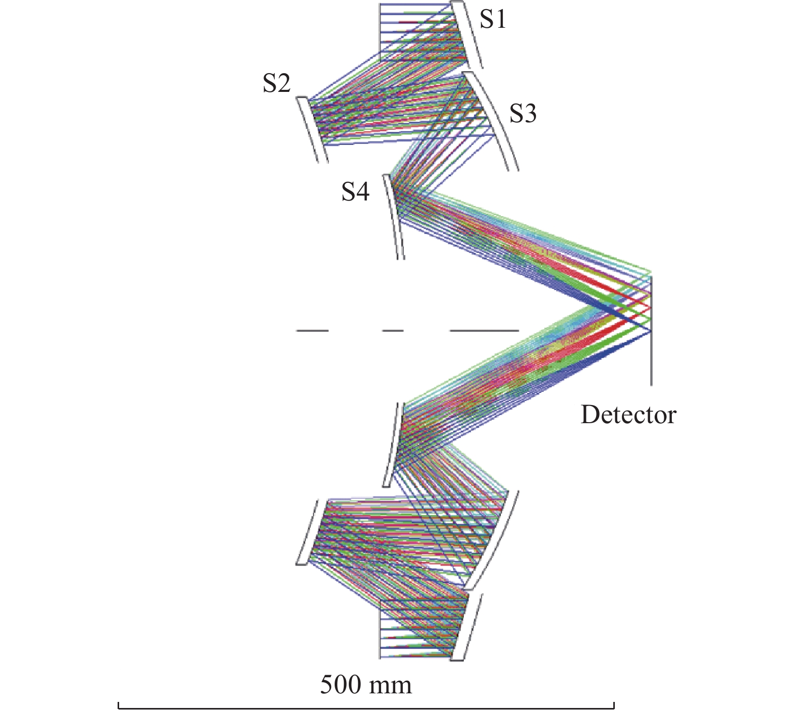
      式中:$c$代表顶点曲率;$r$代表径向坐标;$k$代表二次常数,并设置非球面的最高幂次为16。以点列图大小为评价函数对光学设计结果进行参数优化,得到如图2所示的成像系统,光线从环形入瞳入射到主镜S1,先后经过次镜S2、三镜S3和四镜S4反射后成像于探测器上。主镜和三镜、次镜和四镜分别共用镜坯,系统基本参数如表2所示,优化后的高次非球面系数如表3所示。

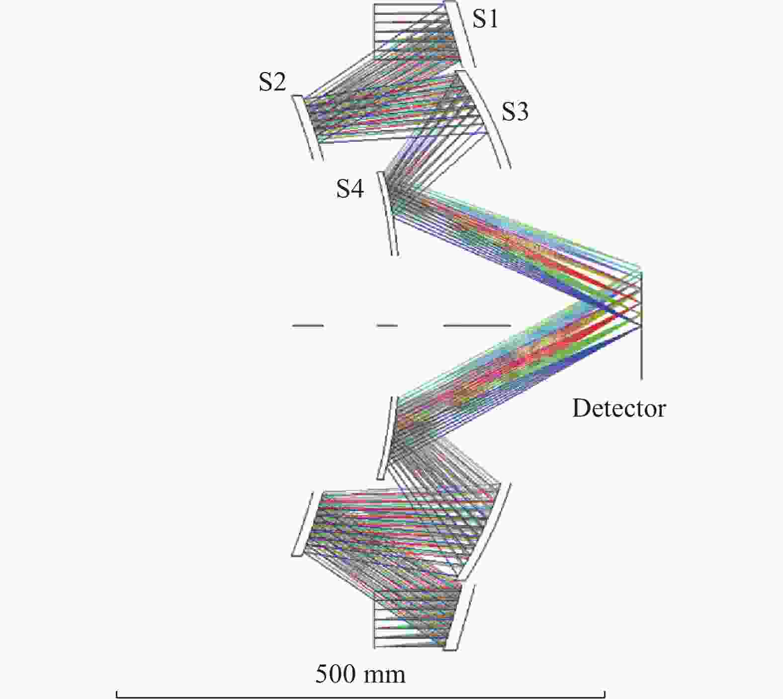
      Figure 2.  Optical layout of the imaging system

      Surface$ {{M}}_{\text{1}} $$ {{M}}_{\text{2}} $$ {{M}}_{\text{3}} $$ {{M}}_{\text{4}} $
      Radius/mm−67.998−239.1149−132.9414−64.7218
      Distance/mm−15.48518.15515−12.7470524.65042
      Diameter/mm66.212952.8635352.7567332.0385
      Conic coefficient0.2919967.760222.859459−25.448

      Table 2.  Basic surface parameters

      Surface$ {{M}}_{\text{1}} $$ {{M}}_{\text{2}} $$ {{M}}_{\text{3}} $$ {{M}}_{\text{4}} $
      A20.0015293882−0.00754166240.00564600090.0015335974
      A4−1.0962896e-0064.375154e-006−2.6497218e-007−1.296045e-005
      A61.5847328e-0103.5537337e-009−1.6551466e-0097.4891721e-009
      A83.3404588e-0133.7951706e-012−3.5939478e-0133.4871654e-011
      A105.8294423e-016−5.2626752e-0151.6072703e-015−4.9330029e-013
      A12−5.4089482e-0194.9805961e-018−3.6151876e-0182.1115162e-015
      A142.6248278e-022−2.5360935e-0212.9968098e-021−4.6380052e-018
      A165.322143e-026−8.9904043e-025−1.1493177e-0244.0505877e-021

      Table 3.  High order aspheric coefficients

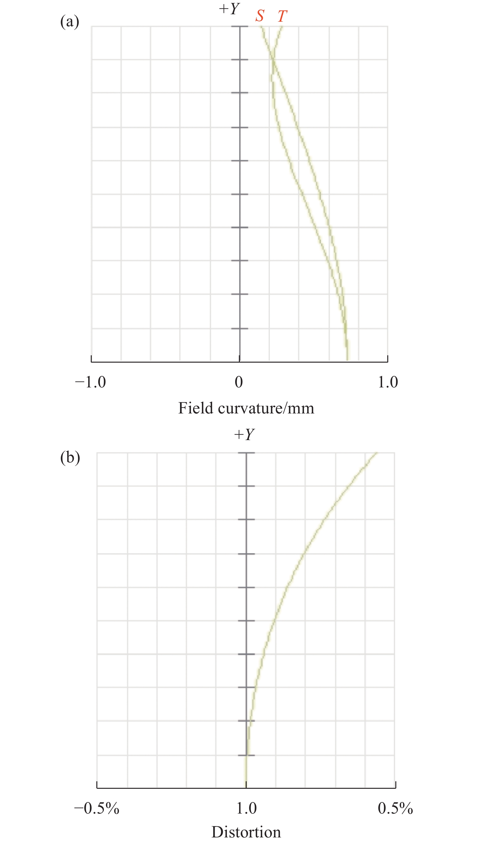
      图3为系统的光学调制传递函数曲线,可以看出全视场内调制函数值接近衍射极限。图4为系统的场曲和畸变曲线,可以看出系统全视场畸变小于1%。

      Figure 3.  Modulation transfer function (MTF) curve

      Figure 4.  (a) Field curvature and (b) distortion curves

    • 主镜与三镜共用一个镜坯,面形均为最高16次的偶次非曲面(Even Asphere),口径均为环形,其中主镜环带外径66.6 mm、内径53 mm;三镜环带外径52.2 mm、内径32.2 mm。设计CGH共用干涉仪实现主镜与三镜的同时检测,使得从干涉仪发出的测试光束中一部分被CGH上的主镜测试全息区域衍射后,调制成与主镜面形匹配的测试波前;另一部分被同一个CGH上的三镜测试全息区域衍射后,调制成与三镜面形匹配的测试波前。考虑到主镜与三镜均为回转对称非球面且具有较大中心遮拦孔,CGH相位函数采用回转对称多项式(如Zemax软件中的Binary 2类型)且设计离焦(power)载频来隔离干扰衍射级次的鬼像。

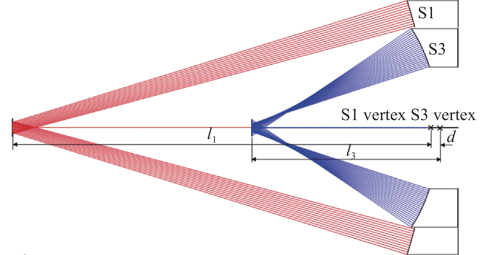
      由于CGH调制后的测试光束是法向入射到被测非球面后沿着原路反射回来,满足零位测试(Null Test)条件,首先计算被测非球面法向光线如图5所示。主镜(S1)非球面度峰谷值(Peak-to-Valley,PV)约35.4λ λ=632.8 nm为干涉仪工作波长,下同),最小弥散斑位置到其顶点距离为l1=109.589 mm,三镜(S3)非球面度PV约162.8λ,最小弥散斑位置到其顶点距离为l3=49.367 mm,主镜与三镜顶点距离由前述成像系统设计给出d=2.669875 mm。在设计CGH时必须确保主镜与三镜处于正确的相对位置。

      Figure 5.  Calculation of normal rays reflected off the test surface to determine the CGH position

      由于被测面口径不大,确定CGH位置时一方面考虑“萌芽时就消灭它”的消像差原则,应将CGH尽可能靠近被测面(预留安全距离方便检测装调);另一方面,像点应取主镜与三镜最小弥散斑位置的中间位置,这相当于在两个测试全息的相位函数中加入了不同的离焦载频,可以方便地隔离干扰级次。此外,因为像点就是干涉仪的标准球面镜头(Transmission Sphere,TS)的焦点,像点位置决定了球面测试波前的f/数,应与干涉仪TS的f/数匹配。

      CGH采用光掩模制作工艺进行加工,使用标准的6025铬板6 in (1 in=2.54 cm)熔石英平板、厚约6.4 mm)。CGH到三镜顶点距离18 mm,到主镜顶点距离15.330125 mm,到像点距离45 mm,优化CGH的相位函数使得波像差均方根(Root-Mean-Squares, RMS)值最小。主镜和三镜CGH相位函数的多项式分别取6和12项,优化后的波像差残差RMS值均为零。如图6所示,主镜与三镜共用CGH及干涉仪点光源,主镜测试全息区域为ϕ44.4~58.4 mm环带,三镜测试全息区域为ϕ19.2~32.8 mm环带。同时,在CGH中心ϕ19 mm区域设计辅助对准全息,用于对转CGH与干涉仪点光源。CGH上三个全息区域均采用Binary 2类型的回转对称图样,其中主镜测试全息的最小条纹周期为2.5 μm,三镜测试全息的最小条纹周期为2.9 μm,均采用+1级衍射,对于占空比为0.5的二元台阶振幅型CGH,其衍射效率约10%,适用于金属反射镜等高反射率面形检测。辅助对准全息可采用+3级衍射,最小条纹周期为4.6 μm,衍射效率约1%,与干涉仪TS参考面4%反射率也能很好地匹配,获得较好的干涉条纹对比度。

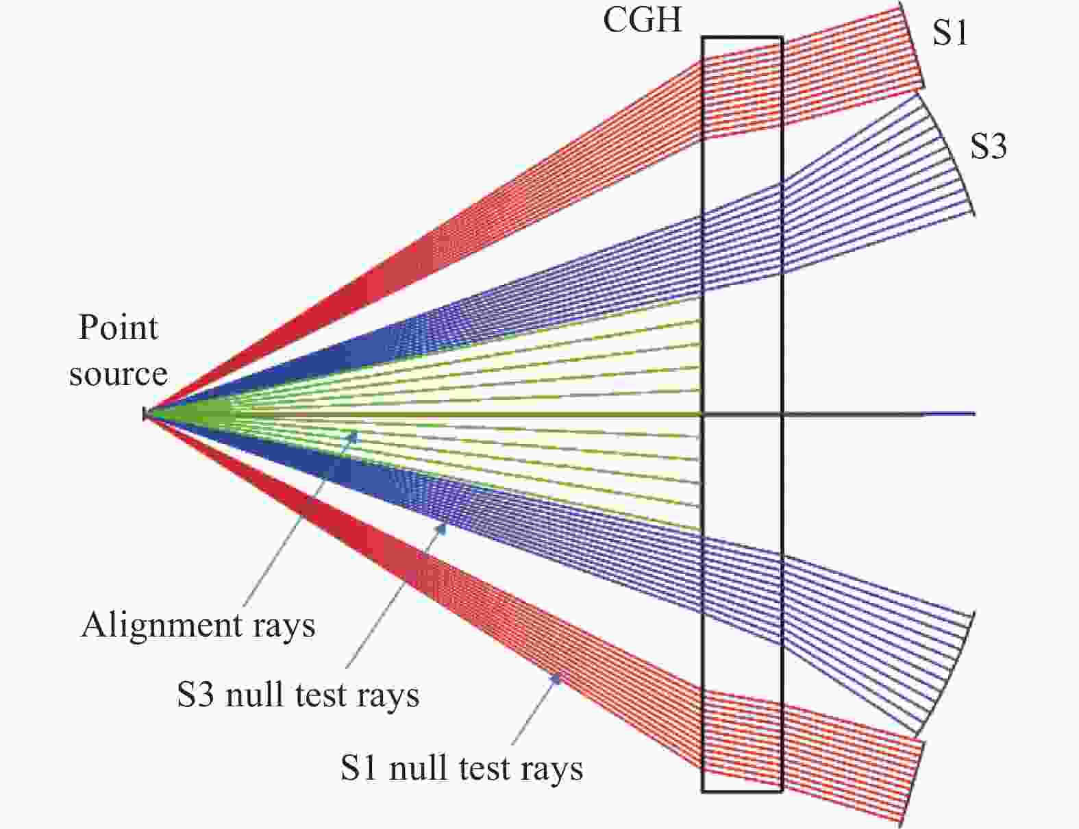
      Figure 6.  CGH design for the primary mirror and the tertiary mirror

      CGH设计必须检查有无其他衍射级次的鬼像干扰,利用光学设计软件的光线追迹功能,如Zemax中通过Multi-Configuration设置不同衍射级次的组合(光线往返),在适当直径的像平面针孔滤波下,查看干扰级次的光线是否被有效遮拦而不能到达像平面。针孔直径所对应的空间频率通常应大于干涉仪CCD像素间隔所确定的Nyquist采样频率,即尽量避免因隔离干扰级次而设置的针孔滤波降低测量系统的空间分辨率。根据CGH设计结果,假设干涉仪CCD像素为1000 pixel×1000 pixel,主镜与三镜检测的针孔直径分别取0.6 mm与1 mm,经检查确认各级衍射级次没有鬼像干扰。值得一提的是,三镜CGH较易出现(+3,0)、(0,+3)级次组合的鬼像干扰,如果将CGH到像点距离改为43 mm,CGH到三镜顶点距离改为20 mm,则存在如图7所示(+3,0)级次组合的鬼像。此时即使调整CGH到像点距离(改变离焦载频)也不能改善,而将CGH到三镜顶点距离改为18 mm则可以避免鬼像干扰,如图8所示,三镜反射回来的光线可被直径1 mm的针孔完全遮挡,不会进入探测器像面。

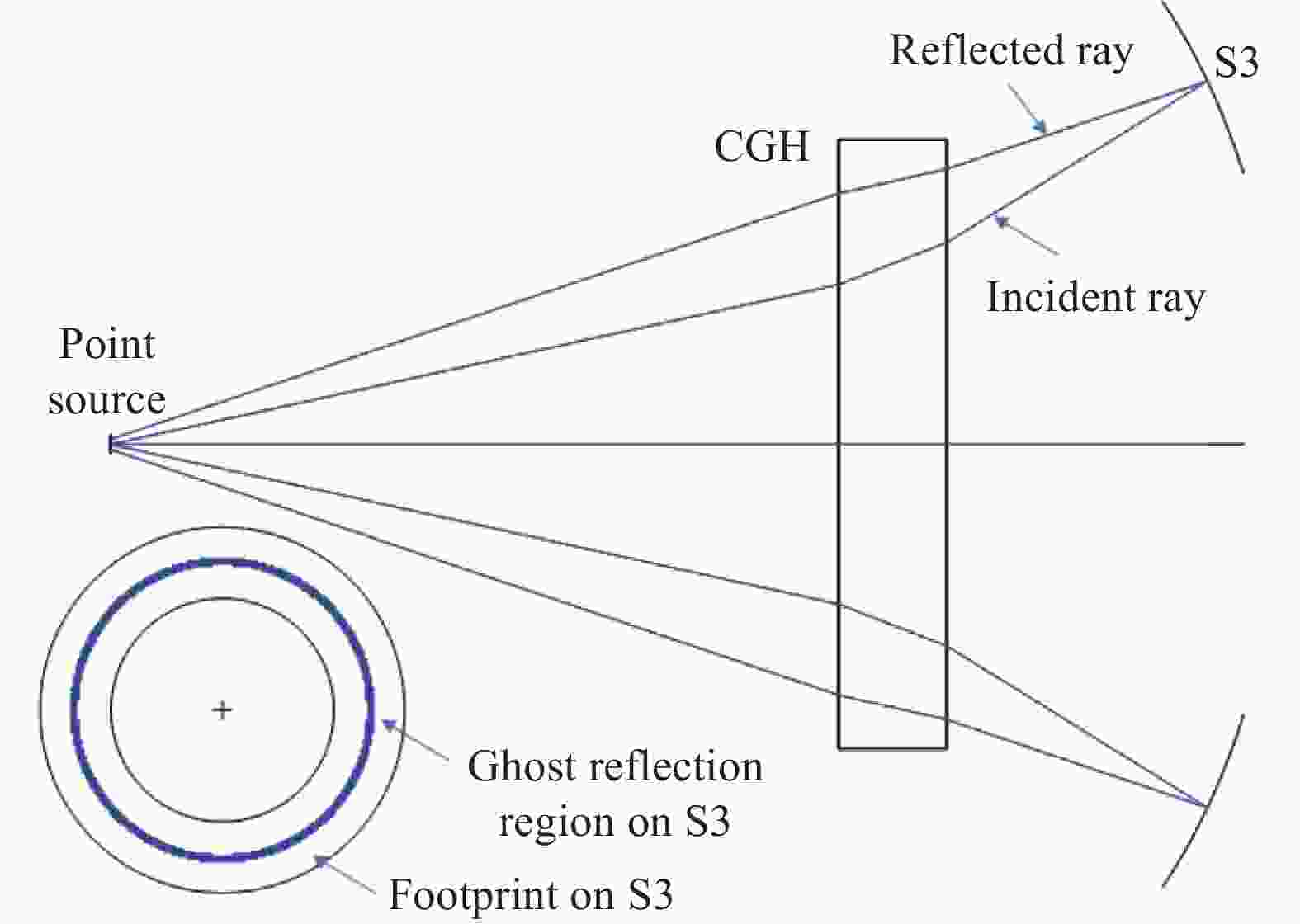
      Figure 7.  Annular ghost fringes generated by (+3, 0) orders when the distances of CGH to the point source and the tertiary mirror are 43 mm and 20 mm, respectively

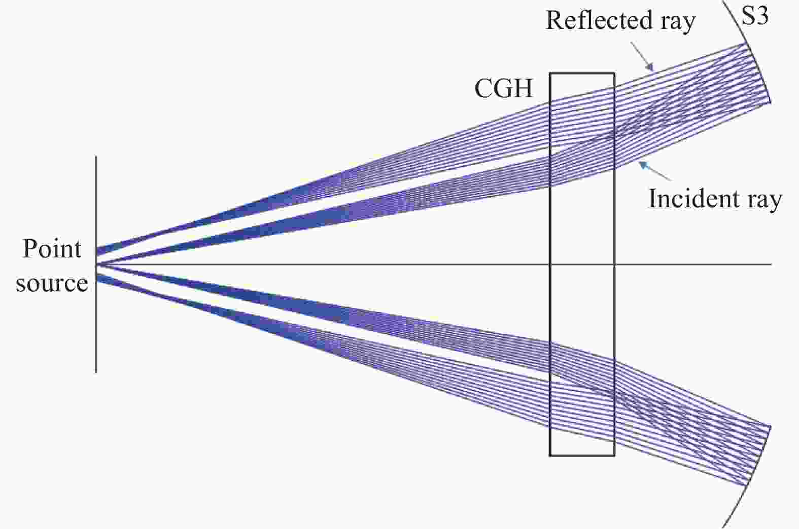
      Figure 8.  Ghost fringes are eliminated when the distances of CGH to the point source and the tertiary mirror are 45 mm and 18 mm, respectively

      对于回转对称全息图样,还应检查CGH测试全息反射的鬼像干扰,因为测试球面波前可能与CGH反射非球面波前在某个环带处匹配(接近等光程),从而形成环带鬼像。经检查确认,主镜和三镜的CGH测试全息反射不会形成鬼像干扰。

    • 次镜与四镜共用一个镜坯,面形均为最高16次的偶次非曲面,口径均为环形,其中次镜环带外径47.2 mm、内径34 mm;四镜环带外径31.6 mm、内径14.4 mm。与主镜和三镜类似,CGH相位函数采用回转对称多项式且设计离焦载频来隔离干扰衍射级次的鬼像。不同的是,次镜与四镜都是凸非球面,检测时置于干涉仪TS参考面与焦点之间,需与TS的f/数及参考面曲率半径匹配。因为需要加入离焦载频,测试球面波的f/数不应与被测非球面最佳拟合球面的R/数(曲率半径与口径之比)接近,这里选用f/3.3左右的TS,CGH到次镜顶点距离20 mm,到四镜顶点距离14.591901 mm。次镜和四镜CGH相位函数的多项式均取6项,优化后的波像差残差RMS值约0.0005λ。若选用4 in TS,如图9所示,次镜与四镜共用CGH及干涉仪点光源,点光源即TS焦点(图中未显示)到参考面距离298.03 mm。为确保TS参考面有效口径够大,参考面到CGH的距离应不小于60 mm。

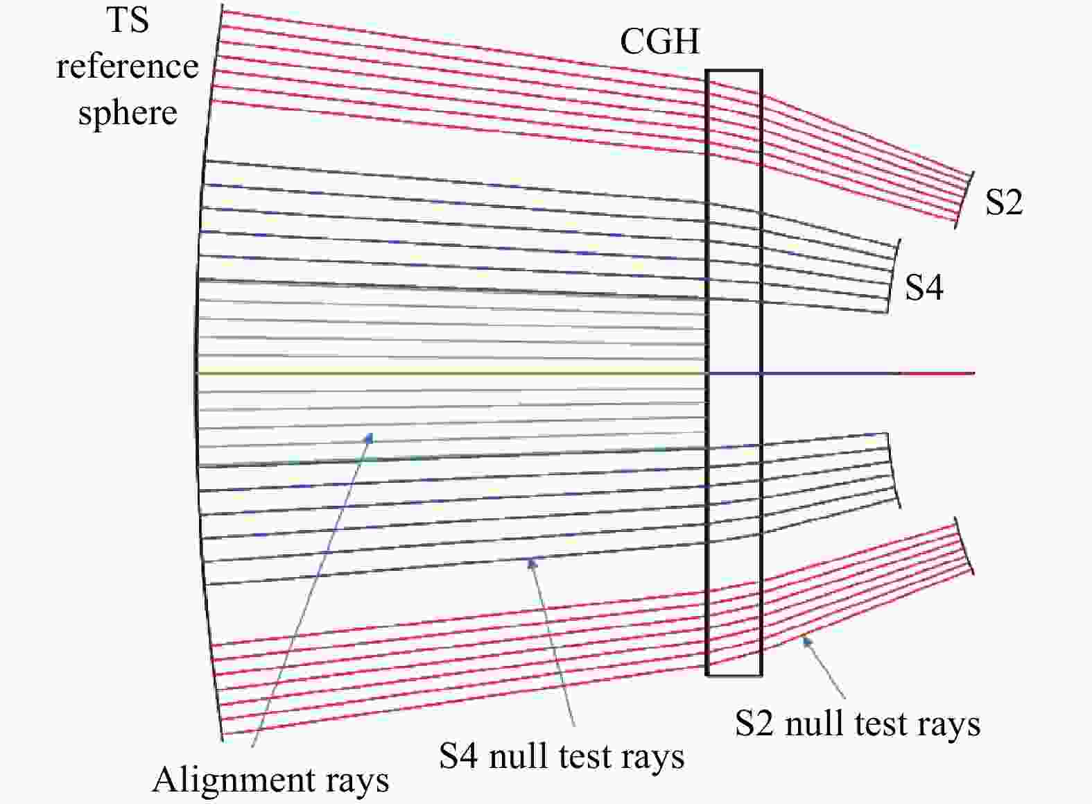
      Figure 9.  CGH design for the secondary mirror and the fourth mirror with a 4-inch f/3.3 TS

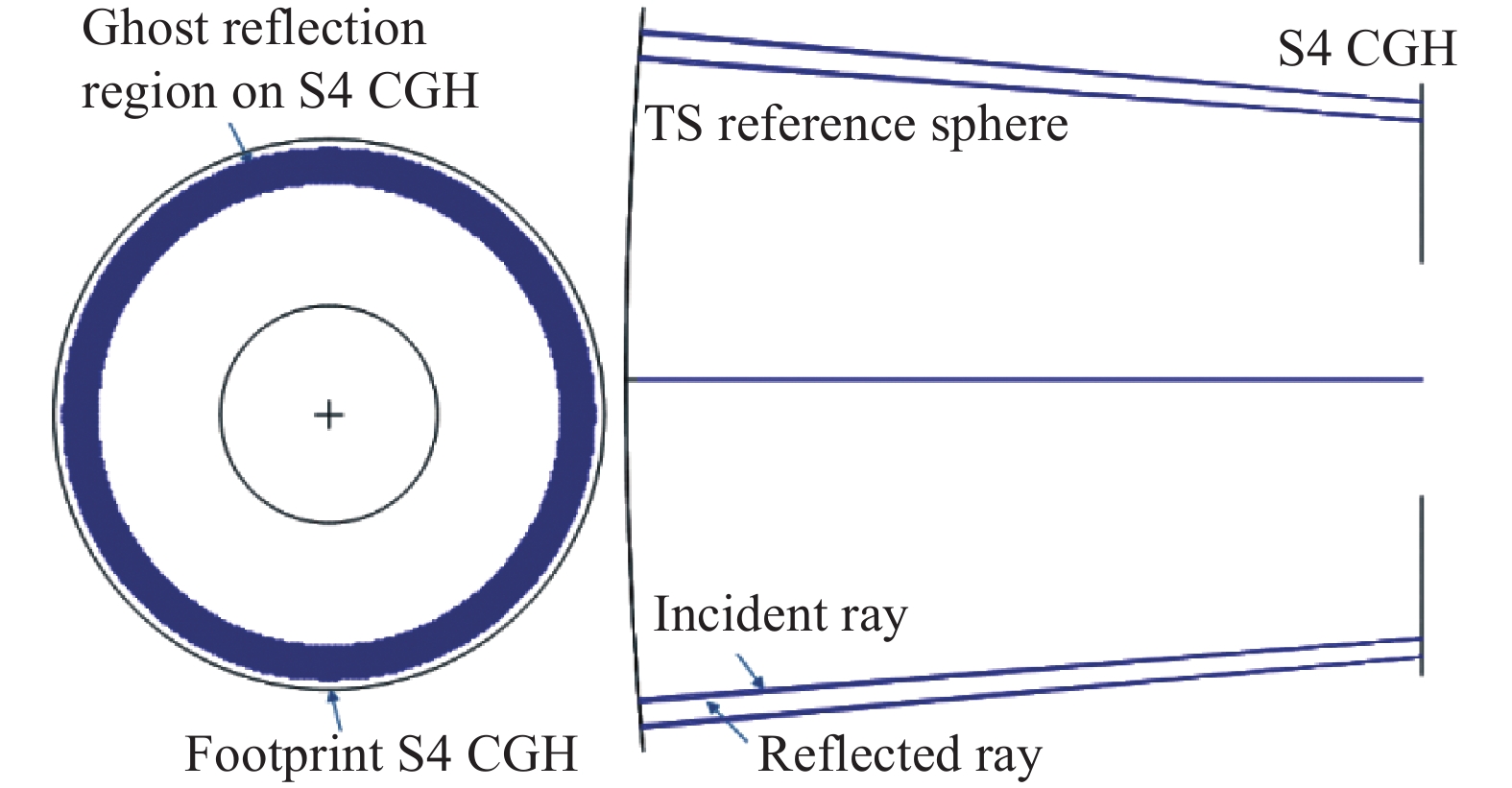
      设置次镜与四镜检测时的像面针孔直径为1.1 mm与1.7 mm,经检查确认各级衍射没有鬼像干扰,但四镜测试全息存在自身反射鬼像。图10所示为CGH上−1级衍射(反射)形成的环带鬼像区域,会与非球面测试时的干涉图混叠在一起形成干扰。

      Figure 10.  Ghost reflection of the fourth mirror CGH (−1 order) with a 4-inch f/3.3 TS

      为了消除鬼像干扰,改用6 in f/3.5 TS,TS焦点到参考面距离475.8 mm,调整TS参考面到CGH距离为150 mm,如图11所示。设置次镜与四镜检测时的像面针孔直径为1.5 mm与2.3 mm,检查各级衍射及CGH自身反射均无鬼像,满足共轴折叠的多面共体反射镜的高精度检测要求。

      Figure 11.  CGH design for the secondary mirror and the fourth mirror with a 6-inch f/3.5 TS

      次镜测试全息区域为ϕ48.8~71.2 mm环带,四镜测试全息区域为ϕ17.6~44.6 mm环带。同时,在CGH中心ϕ17.4 mm区域设计辅助对准全息,用于对转CGH与干涉仪点光源。CGH上三个全息区域均采用Binary 2类型的回转对称图样,其中次镜测试全息的最小条纹周期为2.3 μm,四镜测试全息的最小条纹周期为2.8 μm,辅助对准全息的最小条纹周期为11.9 μm,均采用+1级衍射。

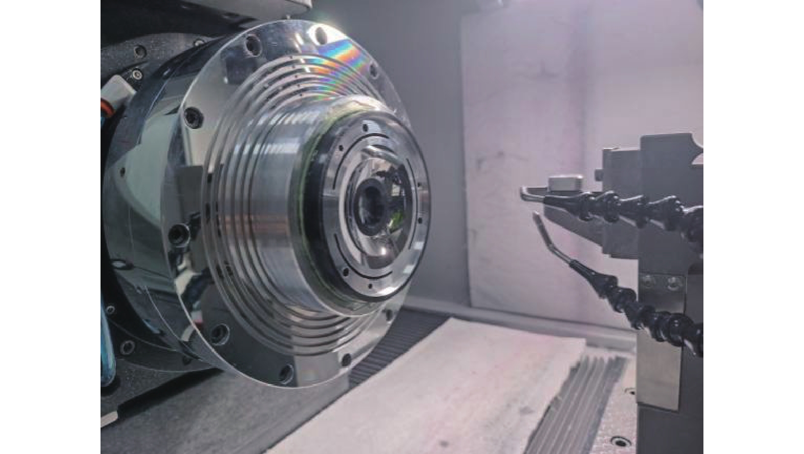
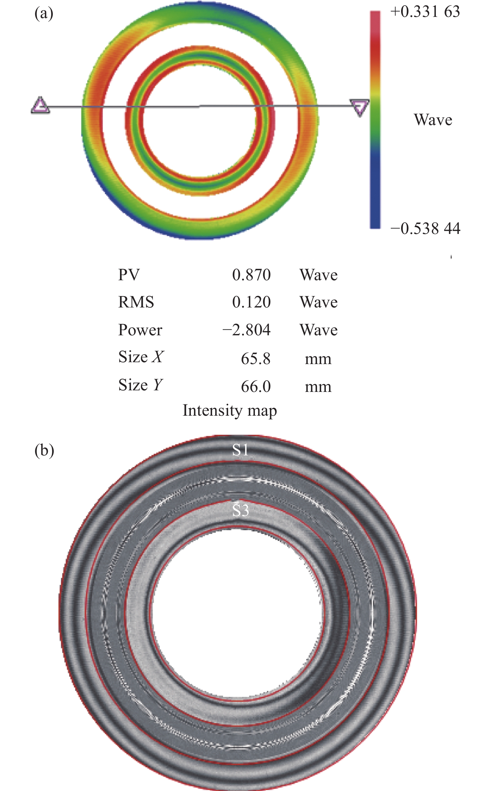
    • 采用金刚石车削工艺进行光学元件加工,主镜和三镜共用镜坯,在同一工序中完成加工,如图12所示。加工后利用单个CGH同时对两个镜面进行零位补偿测量,如图13所示。测得面形误差如图14所示,主镜和三镜看作一个整体的面形误差为PV 0.87λ、RMS 0.12λ。从干涉图中可以看出,鬼像条纹只存在于主镜与三镜条纹区域之外,不形成干扰。主镜和三镜同时达到接近零条纹状态,说明两者的面形精度和相互位姿精度较高(达到亚波长级),满足系统成像要求。由于各个全息区域采用同样的工艺同步制作(例如光掩模制造工艺),其衍射图样的位置误差通常为0.1 μm级,此例中测试全息的刻线周期最小为2.5 μm,不同衍射波前之间的误差小于PV λ/25,确保了共体的多个反射镜之间的相互位姿精度。采用基于CGH补偿的波前干涉方法能够直观检验共体反射镜由于相互位姿误差导致的波像差。而常规的基于位移传感测头扫描测量的方法则需要分别探测两个反射镜面,通过复杂的数据处理(如面形拟合)确定其光轴位置,计算其相互位姿误差,进而评估其对系统成像的波像差影响。受测头误差和扫描运动误差的影响,这种方法的测量精度通常要比波前干涉方法低3~5倍。次镜与四镜的加工、检测方法相同,同样利用CGH补偿获得零条纹状态。将主镜、三镜的镜体与次镜、四镜的镜体装配在一起,几乎不需要额外装调即可实现良好成像。系统装配好后,利用平行光管搭设性能测试光路,测得系统视场为12°,有效焦距为70 mm,角分辨率约为0.052 mrad,均满足设计要求。图15为利用该系统对距离100 m左右的目标成像所采集的图像,可清晰地看到瓷砖缝隙和护栏等窄细特征。

      Figure 12.  Diamond turning of the monolithic primary mirror and tertiary mirror

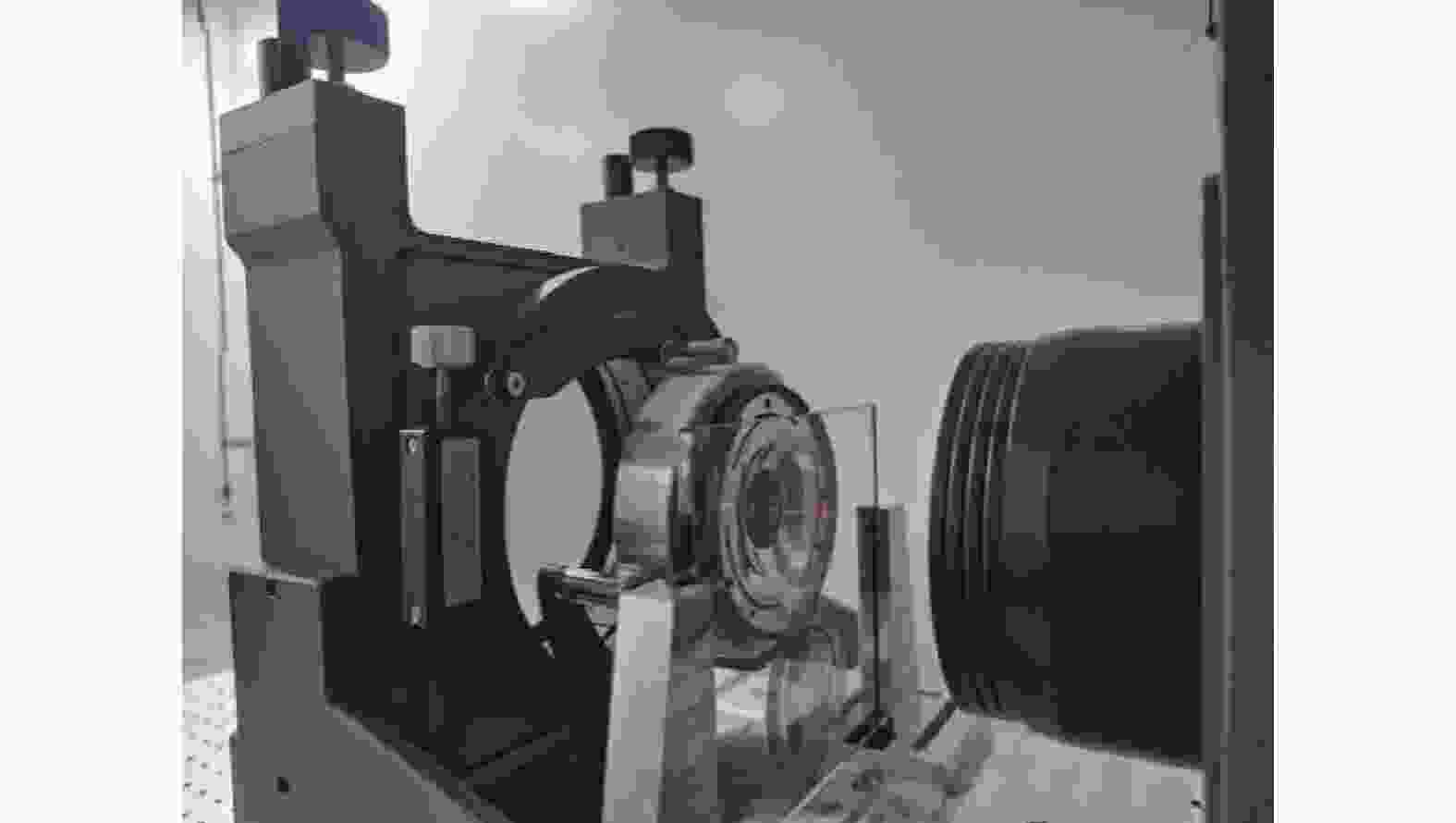
      Figure 13.  CGH null test of the monolithic primary mirror and tertiary mirror

      Figure 14.  Surface error and null fringe interferogram of the primary mirror and tertiary mirror

      Figure 15.  Imaging of targets at distance of about 100 m

    • 文中针对同轴四反成像系统的共体折叠反射镜提出了基于CGH的补偿干涉测量方法。该方法通过在同一个CGH基底上制作多个不同功能的全息区域,使入射测试波前衍射后生成不同形状的非球面波前,可同时对不同反射镜面形进行零位测试。基于CGH补偿测量进行超精密加工后的反射镜面形精度和位姿精度都达到亚波长级,直接装配在一起而无需额外装调即可实现良好成像。同样,通过加工定位基准,同轴嵌套多个类似系统,能方便实现可见光到红外的多个波段共轴成像,对于无人平台目标探测及快速图像融合处理具有明显的优势。

Reference (14)

Catalog

    /

    DownLoad:  Full-Size Img  PowerPoint
    Return
    Return