Volume 52 Issue 6
Jun.  2023
Turn off MathJax
Article Contents

Tan Zhongqi, Ji Hongteng, Mao Yuanhao, Wu Geng, Jiang Xiaowei, Guan Shiyu, Chen Dingbo, Quan Yuchuan. Review of backscattering problems in optical gyros (invited)[J]. Infrared and Laser Engineering, 2023, 52(6): 20230181. doi: 10.3788/IRLA20230181
Citation: Tan Zhongqi, Ji Hongteng, Mao Yuanhao, Wu Geng, Jiang Xiaowei, Guan Shiyu, Chen Dingbo, Quan Yuchuan. Review of backscattering problems in optical gyros (invited)[J]. Infrared and Laser Engineering, 2023, 52(6): 20230181. doi: 10.3788/IRLA20230181

Review of backscattering problems in optical gyros (invited)

doi: 10.3788/IRLA20230181
Funds:  Science Foundation for Indigenous Innovation of National University of Defense Technolog (22-ZZCX-063); Natural Science Foundation of Hunan Province of China (2023JJ30639)
  • Received Date: 2023-03-20
  • Rev Recd Date: 2023-05-20
  • Available Online: 2023-07-04
  • Publish Date: 2023-06-25
  •   Significance   Optical gyro, as an indispensable part of the modern inertial navigation technology, has been widely used in aerospace, military equipment and even civil field. It is based on Sagnac effect, which induces the optical difference between two signals propagating in opposite directions within the optical path rotation. So far, optical gyro has developed from traditional laser gyro to fiber optic gyro and integrated optical gyro, which are smaller and consumes less power. In terms of working principle, optical gyro could be divided into two categories, active optical gyro and passive optical gyro. The former is essentially a laser, using the frequency beat of the opposite propagating light to derive the external rotation signal, while the latter is based on the phase or frequency difference generated by the outside laser to measure the rotation. However, both of them are necessary when considering the backscattering problems in gyro during the process of improving the working accuracy.   Progress  In order to better understand the backscattering mechanism in optical gyro, it could start with self-consistent equation under semi-classical theory, followed by analyzing the coupling mode of opposite propagating light wave. And the practical research of backscattering mechanism in optical gyro mainly focuses on lock-in effect and noise characteristics under macro conditions, taking corresponding methods to suppress them. For laser gyros, the lock-in effect caused by backscattering mechanism is usually solved by frequency bias. With the development of optical fiber, fiber optic gyroscope is invented. According to different working principles, it can be divided into interference fiber optic gyroscope, resonant fiber optic gyroscope and Brillouin fiber optic gyroscope. Their manifestation of backscattering is also slightly different. For the fiber optic gyroscope, it is based on the phase difference generated by the interference of the opposite propagating light wave. Therefore, the noise of backscattering disturbs the actual phase measurement. The main solution is to use the wide spectrum light source or phase modulation. For resonator fiber optic gyroscope, the noise caused by backscattering can be divided into two aspects. One is the light intensity of the scattered light wave itself, and the other is the mutual interference between the scattered light and the signal. The former will lead to the nonlinearity of the gyroscope output, while the latter results in the bias noise of the frequency measurement. The common solution is to carry out frequency modulation or phase modulation on the system, which suppresses the effect of backscattering noise. For Brillouin fiber optic gyro, it is an active resonant gyro in essence, like laser gyro. Therefore, frequency bias and phase modulation are often used to overcome the influence of lock-in effect. At present, integrated optical gyro with more fine structure and smaller volume is also a valuable research direction. However, it is identical to fiber optic gyros except for the waveguide resonator or micro resonator. Therefore, there is no great difference with fiber optic gyros in analysis methods for backscattering problems. It is worth noting that the Brillouin gyros on chip, which benefit from the reduction of stimulated Brillouin scattering threshold, can spontaneously generate Stokes light with a large frequency difference, so as to fundamentally solve the problem caused by the lock-in effect.   Conclusions and Prospects  Backscattering in optical gyro is a common phenomenon, which will bring in the inevitable noise or lock-in effect leading to the deterioration of the gyro performance. At present, the common research focuses on using different modulations to suppress the adverse effects of backscattering, with the purpose to improve the performance of gyro. However, there are still some unsolved problems. One is the precision measurement of backscattering in the optical gyro, and the other is to minimize the magnitude of backscattering in the optical gyro through reasonable design and processing. Both of them are beneficial to better understand the backscattering mechanism of optical gyro at the micro level, reduce the adverse effects of backscattering fundamentally, and improve the actual working efficiency of optical gyro. In addition, it is also worth thinking about how to cleverly use the characteristics of backscattering, remove its adverse aspects, and promote its application in precision measurement.
  • [1] Post E J. Sagnac effect [J]. Reviews of Modern Physics, 1967, 39(2): 475-493. doi:  10.1103/RevModPhys.39.475
    [2] Armenice M N, Ciminelli C, Dell’ollo F, et al. Advances in Gyroscope Technologies[M]. Heidelberg: Springer, 2010.
    [3] Tan Zhongqi, Jiang Xiaowei, Mao Yuanhao, et al. Ultra-smooth surface with 0.4 Å roughness on fused silica [J]. Ceramics International, 2023, 49(5): 7245-7251. doi:  10.1016/j.ceramint.2022.08.022
    [4] Menegozzi L N, Lamb W E. Theory of a ring laser [J]. Physical Review A: Atomic, Molecular and Optical Physics, 1973, 8(4): 2103-2125. doi:  10.1103/PhysRevA.8.2103
    [5] Spreeuw R J C, Centeno Neelen R, Van Druten N J, et al. Mode coupling in a He-Ne ring laser with backscattering [J]. Physical Review A: Atomic, Molecular and Optical Physics, 1990, 42(7): 4315-4324. doi:  10.1103/PhysRevA.42.4315
    [6] 姜亚南. 环形激光陀螺[M]. 北京: 清华大学出版社, 1985.
    [7] Stover J. Optical Scattering: Measurement and Analysis[M]. 3rd ed. Bellingham: SPIE Optical Engineering Press, 2012.
    [8] Kröger E, Kretschmann E. Scattering of light by slightly rough surfaces or thin films including plasma resonance emission [J]. Zeitschrift für Physik A Hadrons and Nuclei, 1970, 237(1): 1-15.
    [9] Nakazawa M. Rayleigh backscattering theory for single-mode optical fibers [J]. Journal of the Optical Society of America, 1983, 73(9): 1175-1180. doi:  10.1364/JOSA.73.001175
    [10] Jungwirth D R. Ring laser cavity backscatter measurement. US: 64866591 A[P]. 1991-01-31.
    [11] Fan Zhenfang, Luo Hui, Lu Guangfeng, et al. Online effective backscattering estimation for ring laser gyro [J]. Chinese Optics Letters, 2012, 10(5): 36-38.
    [12] Iwatsuki K, Hotate K, Higashiguchi M. Backscattering in an optical passive ring-resonator gyro: experiment [J]. Applied Optics, 1986, 25(23): 4448-4451. doi:  10.1364/AO.25.004448
    [13] Iwatsuki K, Hotate K, Higashiguchi M. Resonance characteristics of backscattering in optical passive ring-resonator gyro [J]. Electronics Letters, 1986, 22(3): 135-137. doi:  10.1049/el:19860095
    [14] Ma Huilian, He Zuyuan, Hotate K. Sensitivity improvement of waveguide-type optical passive ring resonator gyroscope by carrier suppression[C]//International Conference on Optical Fibre Sensors. 20th International Conference on Optical Fibre Sensors, 2009.
    [15] 曾庆化, 刘建业, 赖际舟, 等. 环形激光陀螺的最新发展[J]. 传感器技术, 2004, 23(11): 1-4.

    Zeng Qinghua, Liu Jianye, Lai Jizhou, et al. Newest developments of ring laser gyro [J]. Journal of Transducer Technology, 2004, 23(11): 1-4. (in Chinese)
    [16] 杨士杰, 唐苗, 汪世林, 等. 激光陀螺背向散射研究综述[J]. 飞控与探测, 2021, 4(6): 25-32.

    Yang Shijie, Tang Miao, Wang Shilin, et al. Review of backscattering in ring laser gyroscope [J]. Flight Control & Detection, 2021, 4(6): 25-32. (in Chinese)
    [17] 周海波, 刘建业, 赖际舟, 等. 光纤陀螺仪的发展现状[J]. 传感器技术, 2005, 24(6): 1-3.

    Zhou Haibo, Liu Jianye, Lai Jizhou, et al. Development status of fiber-optic gyroscopes [J]. Journal of Transducer Technology, 2005, 24(6): 1-3. (in Chinese)
    [18] Vali V, Shorthill R W. Fiber ring interferometer [J]. Applied Optics, 1976, 15(5): 1099-1100. doi:  10.1364/AO.15.001099
    [19] Arditty H, Shaw H J, Chodorow M, et al. Re-entrant fiberoptic approach to rotation sensing[C]//Laser Inertial Rotation Sensors, 1978: 138-148.
    [20] Cutler C C, Newton S A, Shaw H J. Limitation of rotation sensing by scattering [J]. Optics Letters, 1980, 5(11): 488-490. doi:  10.1364/OL.5.000488
    [21] 张桂才. 光纤陀螺原理与技术[M]. 北京: 国防工业出版社, 2008.
    [22] Martin J M, Winkler J T. Fiber optic laser gyro signal detection and processing technique[C]//Guided Wave Optical Systems and Devices I, 1978: 98-102.
    [23] Böhm K, Russer P, Weidel E, et al. Low-noise fiber-optic rotation sensing [J]. Optics Letters, 1981, 6(2): 64-66. doi:  10.1364/OL.6.000064
    [24] Sanghadasa M, Ashley P R, Lindsay G A, et al. Backscatter compensation in IFOG based inertial measurement units with polymer phase modulators [J]. Journal of Lightwave Technology, 2009, 27(6): 806-813. doi:  10.1109/JLT.2008.928915
    [25] Lloyd Seth W, Dangui Vinayak, Digonnet Michel J F, et al. Measurement of reduced backscattering noise in laser-driven fiber optic gyroscopes [J]. Optics Letters, 2010, 35(2): 121-123. doi:  10.1364/OL.35.000121
    [26] Fei Teng, Jin Jing, Zhang Zuchen, et al. Measurement of back-reflection and backscattering noise in high sensitivity photonic crystal fibre-optic gyroscope[C]//Laser Science, 2016.
    [27] Suo Xinxin, Yu Haicheng, Yang Yongbin, et al. Ultralow-noise broadband source for interferometric fiber optic gyroscopes employing a semiconductor optical amplifier [J]. Applied Optics, 2021, 60(11): 3103-3107. doi:  10.1364/AO.419969
    [28] Balsamo S R, Ezekiel S. Passive ring resonator laser gyroscope [J]. Applied Physics Letters, 1977, 30(9): 478-480. doi:  10.1063/1.89455
    [29] Shupe D M. Fiber resonator gyroscope: sensitivity and thermal nonreciprocity [J]. Applied Optics, 1981, 20(2): 286-289. doi:  10.1364/AO.20.000286
    [30] Wang Zhuo, Wang Guochen, Kumar S, et al. Recent advancements in resonant fiber optic gyro - A review [J]. IEEE Sensors Journal, 2022, 22(19): 18240-18252. doi:  10.1109/JSEN.2022.3195502
    [31] Iwatsuki K, Hotate K, Higashiguchi M. Effect of Rayleigh backscattering in an optical passive ring-resonator gyro [J]. Applied Optics, 1984, 23(21): 3916-3924. doi:  10.1364/AO.23.003916
    [32] Iwatsuki K, Hotate K, Higashiguchi M. Rayleigh backscattering in optical passive ring-resonator gyro[C]//2nd Intl Conf on Optical Fiber Sensors: OFS'84, 1984: 313-316.
    [33] Carroll R, Potter J E. Backscatter and the resonant fiber-optic gyro scale factor [J]. Journal of Lightwave Technology, 1989, 7(12): 1895-1900. doi:  10.1109/50.41606
    [34] Kaiser T J, Cardarelli D, Walsh J G. Experimental developments in the RFOG[C]//Fiber Optic and Laser Sensors VIII, 1991: 121-126.
    [35] Sanders G A, Prentiss M G, Ezekiel S. Passive ring resonator method for sensitive inertial rotation measurements in geophysics and relativity [J]. Optics Letters, 1981, 6(11): 569-571. doi:  10.1364/OL.6.000569
    [36] Meyer R E, Ezekiel S, Stowe D W, et al. Passive fiber-optic ring resonator for rotation sensing [J]. Optics Letters, 1983, 8(12): 644-646. doi:  10.1364/OL.8.000644
    [37] Zarinetchi F, Ezekiel S. Observation of lock-in behavior in a passive resonator gyroscope [J]. Optics Letters, 1986, 11(6): 401-403. doi:  10.1364/OL.11.000401
    [38] Takiguchi K, Hotate K. Removal of lock-in phenomenon in optical passive ring-resonator gyros by using optical Kerr effect in fiber resonator [J]. IEEE Photonics Technology Letters, 1992, 4(7): 810-812. doi:  10.1109/68.145280
    [39] Hotate K, Takiguchi K, Hirose A. Adjustment-free method to eliminate the noise induced by the backscattering in an optical passive ring-resonator gyro [J]. IEEE Photonics Technology Letters, 1990, 2(1): 75-77. doi:  10.1109/68.47048
    [40] 焦新泉, 郑永秋, 安盼龙, 等. 谐振式光纤陀螺双光路调相谱最优参数确定方法[J]. 红外与激光工程, 2015, 44(1): 239-243.

    Jiao Xinquan, Zheng Yongqiu, An Panlong, et al. Method for determining optimized phase modulation parameters in resonator fiber optic gyro [J]. Infrared and Laser Engineering, 2015, 44(1): 239-243. (in Chinese)
    [41] Liu Ning, Niu Yanxiong, Feng Lishuang, et al. Suppression of backscattering induced noise by the sideband locking technique in a resonant fiber optic gyroscope [J]. Chinese Optics Letters, 2018, 16(1): 42-46.
    [42] Jiao Hongchen, Feng Lishuang, Zhang Chunqi, et al. Design of low-crosstalk polarizing resonator and homologous multi-frequency differential detection for hollow-core photonic-crystal fiber optic gyro [J]. Optics Express, 2019, 27(14): 19536-19547. doi:  10.1364/OE.27.019536
    [43] Zhang Yonggui, Feng Lishuang, Li Hui, et al. Resonant fiber optic gyroscope with three-frequency differential detection by sideband locking [J]. Optics Express, 2020, 28(6): 8423-8435. doi:  10.1364/OE.384636
    [44] Wu Jiangfeng, Smiciklas M, Strandjord L, et al. Resonator fiber optic gyro with high backscatter-error suppression using two independent phase-locked lasers[C]//24 th International Conference on Optical Fibre Sensors, 2015.
    [45] Strandjord L, Qiu T, Salit M, et al. Improved bias performance in resonator fiber optic gyros using a novel modulation method for error suppression[C]//Optical Fiber Sensors, 2018.
    [46] Li Hanzhao, Lin Yi, Lu Liu, et al. Signal processing improvement of passive resonant fiber optic gyroscope using a reciprocal modulation-demodulation technique [J]. Optics Express, 2020, 28(12): 18103-18111. doi:  10.1364/OE.390605
    [47] Zou Kang, Lei Wang, Chen Kan, et al. Optimization of reciprocal modulation parameters in resonant fiber optic gyro [J]. Journal of Lightwave Technology, 2021, 39(17): 5669-5675. doi:  10.1109/JLT.2021.3090989
    [48] Liu Lu, Li Hanzhao, Liu Shuang, et al. Suppressing backscattering noise of a resonant fiber optic gyroscope using coherent detection [J]. Applied Optics, 2022, 61(15): 4421-4428. doi:  10.1364/AO.456095
    [49] Zhao Shuangxiang, Liu Qingwen, Liu Yuanyuan, et al. Navigation-grade resonant fiber-optic gyroscope using ultra-simple white-light multibeam interferometry [J]. Photonics Research, 2022, 10(2): 542-549. doi:  10.1364/PRJ.443496
    [50] Hill K O, Johnson D C, Kawasaki B S. CW Brillouin laser [J]. Applied Physics Letters, 1976, 28(10): 608-609. doi:  10.1063/1.88583
    [51] Thomas P J, Driel H M, Stegeman G I. Possibility of using an optical fiber brillouin ring laser for inertial sensing [J]. Applied Optics, 1980, 19(12): 1906-1908. doi:  10.1364/AO.19.001906
    [52] Kadiwar R K, Giles I P. Optical fibre Brillouin ring laser gyroscope [J]. Electronics Letters, 1989, 25(25): 1729-1731. doi:  10.1049/el:19891157
    [53] Zarinetchi F, Smith S P, Ezekiel S. Stimulated Brillouin fiber-optic laser gyroscope [J]. Optics Letters, 1991, 16(4): 229-231. doi:  10.1364/OL.16.000229
    [54] Huang Shangyuan, Toyama K, Nicati P A , et al. Brillouin fiber optic gyro with push-pull phase modulator and synthetic heterodyne detection[C]//OAI, 1993: 48-59.
    [55] Hotate K, Yamashita S. Grasp of the behavior of lock-in phenomenon and a manner to overcome it in Brillouin fiber optic gyro[C]//Proceedings of the 1998 Fiber Optic and Laser Sensors and Applications, Including Distributed and Multiplexed Fiber Optic Sensors VII, 1998: 57-65.
    [56] 耿靖童, 杨柳, 赵舒华, 等. 谐振式微光学陀螺仪谐振微腔的最新进展[J]. 红外与激光工程, 2021, 50(8): 333-339.

    Geng Jingtong, Yang Liu, Zhao Shuhua, et al. Recent development of resonant micro cavity in resonant micro-optical gyro [J]. Infrared and Laser Engineering, 2021, 50(8): 20210044. (in Chinese)
    [57] Lawrence A W. Thin film laser gyro. US: 7738179A [P]. 1979-09-02.
    [58] Iwatsuki K. Waveguide-type optical passive ring resonator gyro using time-division detection scheme [J]. Electronics Letters, 1989, 25(11): 688-689. doi:  10.1049/el:19890465
    [59] Vannahme C, Suche H, Reza S, et al. Integrated Optical Ti: LiNbO3 ring resonator for rotation rate sensing[C]//ECIO, 2009.
    [60] Suzuki K, Takiguchi K, Hotate K. Monolithically integrated resonator microoptic gyro on silica planar lightwave circuit [J]. Journal of Lightwave Technology, 2000, 18(1): 66-72. doi:  10.1109/50.818908
    [61] Mao Hui, Ma Huilian, Jin Zhonghe. Resonator micro-optic gyroscope based on the double phase modulation technique[C]//CLEO/QELS: 2010 Laser Science to Photonic Applications, 2010.
    [62] Yu Huaiyong, Zhang Chunxi, Feng Lishuang, et al. Limitation of rotation sensing in IORG by Rayleigh backscattering noise [J]. Europhysics Letters, 2011, 95(6): 64001-64004. doi:  10.1209/0295-5075/95/64001
    [63] Zhi Yinzhou, Feng Lishuang, Wang Junjie, et al. Reduction of backscattering noise in a resonator integrated optic gyro by double triangular phase modulation [J]. Applied Optics, 2015, 54(1): 114-122. doi:  10.1364/AO.54.000114
    [64] Niu Jian, Liu Wenyao, Pan Ziwen, et al. Reducing backscattering and the Kerr noise in a resonant micro-optic gyro using two independent lasers [J]. Applied Optics, 2021, 60(10): 2761-2766. doi:  10.1364/AO.417006
    [65] Liu Shuang, Hu Junyi, Wang Yuxin, et al. Broadband source-driven resonant micro-optic gyroscope based on a multi-turn waveguide-type ring resonator [J]. Optics Letters, 2023, 48(5): 1152-1155. doi:  10.1364/OL.479092
    [66] Xie Chengfeng, Tang Jun, Cui Danfeng, et al. Resonant microsphere gyroscope based on a double Faraday rotator system [J]. Optics Letters, 2016, 41(20): 4783-4786. doi:  10.1364/OL.41.004783
    [67] Li Jiang, Suh M G, Vahala K. Microresonator Brillouin gyroscope [J]. Optica, 2017, 4(3): 346-348. doi:  10.1364/OPTICA.4.000346
    [68] Gundavarapu S, Brodnik G M, Puckett M, et al. Sub-hertz fundamental linewidth photonic integrated Brillouin laser [J]. Nature Photonics, 2018, 13: 60-67.
    [69] Nelson K D, Puckett M W, Wu Jianfeng. A ring-laser gyro based on stimulated Brillouin scattering in silicon nitride waveguides[C]//2020 IEEE Research and Applications of Photonics in Defense Conference (RAPID), 2020.
    [70] Lai Yuhung, Suh M G, Lu Yukun, et al. Earth rotation measured by a chip-scale ring laser gyroscope [J]. Nature Photonics, 2020, 14(6): 345-349. doi:  10.1038/s41566-020-0588-y
  • 加载中
通讯作者: 陈斌, bchen63@163.com
  • 1. 

    沈阳化工大学材料科学与工程学院 沈阳 110142

  1. 本站搜索
  2. 百度学术搜索
  3. 万方数据库搜索
  4. CNKI搜索

Figures(20)  / Tables(1)

Article Metrics

Article views(351) PDF downloads(102) Cited by()

Related
Proportional views

Review of backscattering problems in optical gyros (invited)

doi: 10.3788/IRLA20230181
  • 1. College of Advanced Interdisciplinary Studies, National University of Defense Technology, Changsha 410073, China
  • 2. Nanhu Laser Laboratory, National University of Defense Technology, Changsha 410073, China
  • 3. Huaguan Technology Co., Ltd., Changsha 410073, China
Fund Project:  Science Foundation for Indigenous Innovation of National University of Defense Technolog (22-ZZCX-063); Natural Science Foundation of Hunan Province of China (2023JJ30639)

Abstract:   Significance   Optical gyro, as an indispensable part of the modern inertial navigation technology, has been widely used in aerospace, military equipment and even civil field. It is based on Sagnac effect, which induces the optical difference between two signals propagating in opposite directions within the optical path rotation. So far, optical gyro has developed from traditional laser gyro to fiber optic gyro and integrated optical gyro, which are smaller and consumes less power. In terms of working principle, optical gyro could be divided into two categories, active optical gyro and passive optical gyro. The former is essentially a laser, using the frequency beat of the opposite propagating light to derive the external rotation signal, while the latter is based on the phase or frequency difference generated by the outside laser to measure the rotation. However, both of them are necessary when considering the backscattering problems in gyro during the process of improving the working accuracy.   Progress  In order to better understand the backscattering mechanism in optical gyro, it could start with self-consistent equation under semi-classical theory, followed by analyzing the coupling mode of opposite propagating light wave. And the practical research of backscattering mechanism in optical gyro mainly focuses on lock-in effect and noise characteristics under macro conditions, taking corresponding methods to suppress them. For laser gyros, the lock-in effect caused by backscattering mechanism is usually solved by frequency bias. With the development of optical fiber, fiber optic gyroscope is invented. According to different working principles, it can be divided into interference fiber optic gyroscope, resonant fiber optic gyroscope and Brillouin fiber optic gyroscope. Their manifestation of backscattering is also slightly different. For the fiber optic gyroscope, it is based on the phase difference generated by the interference of the opposite propagating light wave. Therefore, the noise of backscattering disturbs the actual phase measurement. The main solution is to use the wide spectrum light source or phase modulation. For resonator fiber optic gyroscope, the noise caused by backscattering can be divided into two aspects. One is the light intensity of the scattered light wave itself, and the other is the mutual interference between the scattered light and the signal. The former will lead to the nonlinearity of the gyroscope output, while the latter results in the bias noise of the frequency measurement. The common solution is to carry out frequency modulation or phase modulation on the system, which suppresses the effect of backscattering noise. For Brillouin fiber optic gyro, it is an active resonant gyro in essence, like laser gyro. Therefore, frequency bias and phase modulation are often used to overcome the influence of lock-in effect. At present, integrated optical gyro with more fine structure and smaller volume is also a valuable research direction. However, it is identical to fiber optic gyros except for the waveguide resonator or micro resonator. Therefore, there is no great difference with fiber optic gyros in analysis methods for backscattering problems. It is worth noting that the Brillouin gyros on chip, which benefit from the reduction of stimulated Brillouin scattering threshold, can spontaneously generate Stokes light with a large frequency difference, so as to fundamentally solve the problem caused by the lock-in effect.   Conclusions and Prospects  Backscattering in optical gyro is a common phenomenon, which will bring in the inevitable noise or lock-in effect leading to the deterioration of the gyro performance. At present, the common research focuses on using different modulations to suppress the adverse effects of backscattering, with the purpose to improve the performance of gyro. However, there are still some unsolved problems. One is the precision measurement of backscattering in the optical gyro, and the other is to minimize the magnitude of backscattering in the optical gyro through reasonable design and processing. Both of them are beneficial to better understand the backscattering mechanism of optical gyro at the micro level, reduce the adverse effects of backscattering fundamentally, and improve the actual working efficiency of optical gyro. In addition, it is also worth thinking about how to cleverly use the characteristics of backscattering, remove its adverse aspects, and promote its application in precision measurement.

    • 1913年,法国科学家萨格纳克设计出一种能够感知旋转的环形干涉仪,并且指出当干涉仪所在惯性系发生转动时,闭合环形光路之中的两束传播方向相反的光束将会出现光程差[1],这种现象被称为萨格纳克效应(Sagnac Effect)。随着1960年激光的问世,其高相干性的特点使得利用萨格纳克效应进行高精度角运动测量成为了可能;从此之后,光学陀螺不断发展成熟,并成长为惯性导航核心元件中不可缺少的一员,在航空航天、军事装备、航海乃至民用领域中均得到了广泛的运用[2]

      到目前为止,光学陀螺已经从传统的激光陀螺发展出体积更小、质量更轻、功耗更低的光纤和微光等类型陀螺,从其工作方式上可以将其分为两大类,即有源光学陀螺与无源光学陀螺。其中,有源光学陀螺,其本质上是一个环形激光器,通过正/反向光束的拍频来敏感外界的转动;而无源光学陀螺则是利用外界激光器产生的激光,通过正/反闭合光路传播产生相位差或是谐振产生频率差来测量转动。无论是哪一类光学陀螺,其内部运转激光的背向散射都将不可避免地影响其精度,因此,光学陀螺的性能优化研究中,都需要深入研究和考虑陀螺内部的背向散射问题。尤其针对激光陀螺,尽管近年来国内在超光滑抛光和超低损耗镀膜等关键技术领域获得突破[3],但对于背向散射的理解和掌控还并不成熟。为此,文中将从光学陀螺中背向散射的基础理论出发,讨论不同类型光学陀螺中背向散射的表现形式,并总结展望出一些仍未解决的问题。

    • 所谓背向散射,顾名思义是指光束传播过程中因各种非理想因素而产生的沿着相反方向散射回来光的现象。这些非理想因素主要包括光路传播过程中的光学元件表面散射、介质散射以及因折射率非均匀而产生的散射等。当环形谐振腔中存在背向散射时,将不可避免地与顺、逆时针激光发生耦合,从而对光学陀螺内部产生的萨格纳克效应造成影响,进而影响陀螺感知角运动的性能。为深入了解背向散射,下面将从理论上分析光学陀螺中背向散射的基本原理,并阐述几种典型背向散射测量方法。

    • 讨论光学陀螺中的背向散射问题,可从半经典框架下的自洽方程组出发,以环形激光陀螺为例,利用正/反向行波表征的自洽方程可以写为[4]

      式中:下标“+”,“−”分别表示正负方向上的行波;Eνϕ分别表示行波的振幅、频率和相位;ν0表示空腔的本征频率;κ表示转动空腔正/反向行波的频差;$ \mathrm{\Delta }{{\rm{e}}}^{i{\delta }_{r}} $表示环形腔折射率突变引入的反射;Q表示品质因数;$ \mathrm{\Theta }{{\rm{e}}}^{i{\delta }_{i}} $表示因环形腔介质引入的吸收;ε0表示真空介电常数;<n>表示环形腔的平均折射率;C、S表示电极化强度的实部、虚部。在不考虑电极化强度的情况下,可以将自洽方程的线性耦合部分表示为[5]

      式中:$ \tilde{K} $表示描述线性耦合过程的耦合矩阵。可以看出,通过求解耦合矩阵$ \tilde{K} $的本征值与本征矢量,能够得到环形腔中线性耦合状态下的本征模式。由公式(1)可知,耦合矩阵$ \tilde{K} $可以表示为:

      实部矩阵$ \tilde{H} $表征的是一种能量守恒机制,其对角元表示转动空腔正/反向行波的频率分裂,非对角元表示折射率突变导致的正/反向行波耦合;而虚部矩阵$ \tilde{A} $表征的则是一种能量耗散机制,其对角元表示环形腔内的能量衰减,非对角元表示环形腔内介质吸收引起的正/反向行波耦合。值得注意的是,非对角元所表征的正/反向行波耦合即是背向散射机制。进一步地,可以将耦合矩阵$ \tilde{K} $表示为如下广义形式:

      式中:β表示一个复数(β=1时表征能量守恒机制,β=i时表征能量耗散机制);W表示无量纲背向散射率(W>0,且为实数);κ定义与公式(1)相同。在这种表示形式中,忽略了由于损耗导致的频率展宽以及背向散射带来的相位变化。求解耦合矩阵$ \tilde{K} $的本征值$ \tilde{\lambda } $,可以得到:

      考虑β=1的情况有:

      此时,本征值$ \tilde{\lambda } $表示的即是环形腔内正/反向行波的频率,可以看到除了转动带来的频差κ外,由于能量守恒的背向散射机制引入,正/反向行波的频率还存在W的劈裂。

      考虑β=i的情况有:

      当$ {\kappa }^{2} > {W}^{2} $时,本征值$ \tilde{\lambda } $仍然表示的是环形腔内正/反向行波的频率,同时存在着与上述情况相反的频率劈裂,而当$ {\kappa }^{2}={W}^{2} $时,即使存在外界转动(κ≠0),正/反向行波之间的频差保持为零,这正是能量耗散的背向散射机制导致的影响,即闭锁效应。

      除此之外,从自洽方程中可以观察到,背向散射机制的引入来源于耦合矩阵$ \tilde{K} $中的非对角项,即表示环形腔折射率突变引入的反射$ {\Delta }{{\rm{e}}}^{i{\delta }_{r}} $,以及表示环形腔腔内介质引入的吸收$ \mathrm{\Theta }{{\rm{e}}}^{i{\delta }_{i}} $ ,这两项分别来自宏观上复介电系数$ \tilde{\varepsilon } $的实部与虚部[6]

      式中:εrεi表示复介电系数的实部与虚部;n0表示环形腔内介质的平均折射率;Δn表示环形腔内介质的突变折射率。

      值得注意的是,此处复介电系数所引入的反射与吸收是着眼于整个陀螺系统而言的,是一种宏观的表现形式。而从陀螺内部组成来看,激光陀螺系统中的散射机制主要来源于光学元件以及增益介质(稀有气体原子),而光纤陀螺与微光陀螺则主要取决于导光介质(杂质粒子)中的散射效应。因此,可以从两个方面对当前陀螺系统中的散射进行考量。一方面为光学元件带来的表面散射,在矢量微扰理论中,单位立体角内散射光与入射光的光强比值可以表示为[7]

      式中:下标“i”,“s”分别表示入射光、散射光;P表示光的功率;λ表示光的波长;θ表示光线与散射表面法线的夹角;φs表示散射光线与入射光线二者在散射表面投影夹角的补角;ε表示散射介质与入射介质二者介电系数的比值;Q表示反射偏振因子;PSD表示散射表面的功率谱密度。关于空间频率fxfy的定义可以表示为:

      由此可以看出,散射表面对光强分布的影响是可以由散射表面的功率谱密度描述,即散射表面存在的起伏变化引起了散射光的空间分布。外界光场使得存在表面起伏的介质产生不同的极化,存在极化起伏的介质表面的远场辐射按照多光束合成的方式即可得到散射光的强度分布[8]

      另一方面,介质元带来的散射效应,考虑在随机稳定介质(统计上均匀且各向同性)之中的瑞利散射系数[9]

      式中:αR表示瑞利散射系数;$ k $表示光波的波数;$ \overrightarrow{{k}_{s}} $表示散射光波的波矢;nr表示折射率的相对扰动;$ \overrightarrow{{r}_{1}} $与$ \overrightarrow{{r}_{2}} $表示相对介质元内参考系的位矢;$ \overrightarrow{{r}_{d}} $表示$ \overrightarrow{{r}_{1}} $与$ \overrightarrow{{r}_{2}} $的相对位矢;dVd表示介质内的积分体积元;Cov表示协方差。由此可以看出,该瑞利散射系数的核心取决于折射率的相对变化,其以统计参数协方差描述了介质中不均匀性表征的散射系数,这种不均匀性是对介质元内部而言的,折射率随着空间位置的变化导致了散射光场的产生。

      但无论是表面散射或是介质元散射,其模型的建立仍然着眼于介质整体的表现形式,难免存在一定的近似条件,对于前者只能考虑在光的波长远大于表面起伏的情况,而后者则假设了折射率的相对扰动需要足够的小。这两种考量虽然对散射具有一定的参照意义,但其仍然是从宏观层面出发,将整个介质作为同一整体进行空间积分,从微观层面上来理解,这两种微扰均是由介质中的多散射元分布不均匀构成的,如何构建从微观粒子散射到宏观折介质整体扰动的过渡表征,是后续进一步理解散射机制的发展方向。

      综上所述,背向散射机制的引入会使得陀螺环形腔中的正/反向行波出现频差偏置或是锁定现象,这正是光学陀螺中散射耦合带来的两大效应,而这种机制来源于复介电系数的非均匀性,主要表现在光学元件表面的非均匀性或是尘埃粒子以及增益介质带来的折射率突变。通常而言,光学陀螺中的背向散射强度较为微弱,尤其是随着超光滑表面抛光技术和超低损耗镀膜等核心关键技术的发展,其背向散射相对量已降低至10−7以下;因此,只有采用更高精度和灵敏度的背向散射测量手段,才能在工艺上进一步优化和控制背散对光学陀螺带来的影响。

    • 针对不同光学陀螺中背向散射带来的频率偏置或是锁定现象,部分学者设计了一些典型测量手段对其进行评估,旨在提供优化系统效能的误差参数。典型的光学陀螺包括:基于空间光路和微晶谐振腔的激光陀螺、基于光纤波导的光纤陀螺以及基于片上微纳光学结构的微光陀螺。这三类光学陀螺背向散射来源各有差异,所采用的测量方案也各有特点。

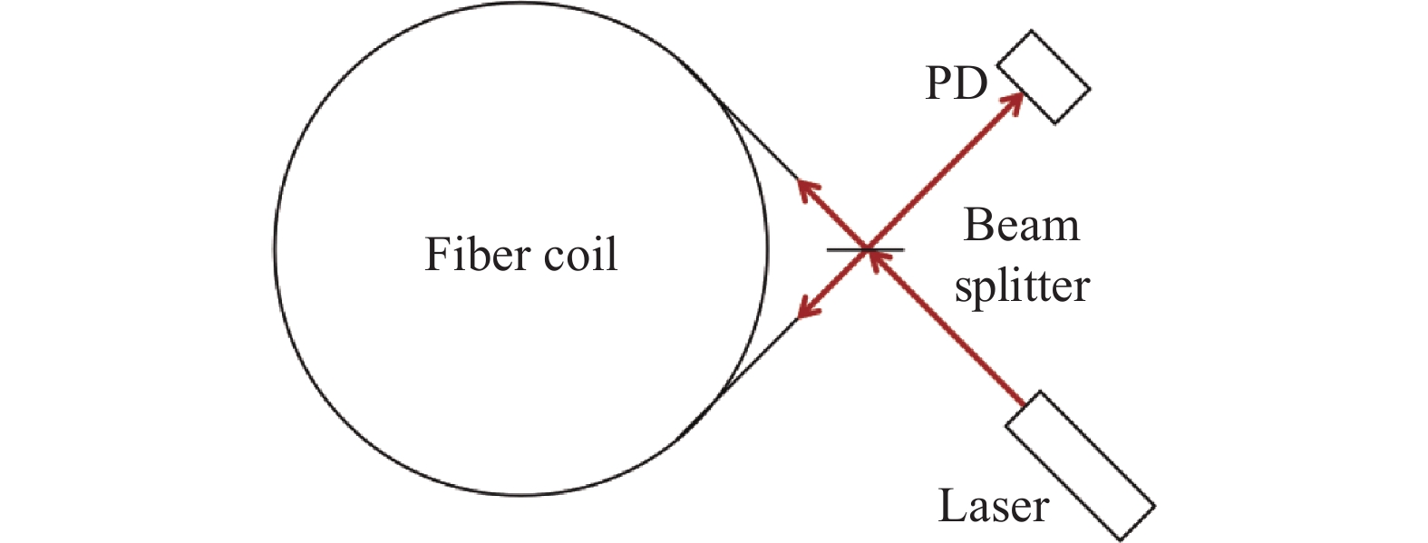
      1991年,Jungwirth D R设计了一种在无源状态下,利用激光陀螺谐振腔测量背向散射系数的方法,见图1,其利用调制盘上的开孔来确保当正/反向入射光束在谐振腔内传播时,探测器上检测到其产生的反/正向背散光束,并给出了计算锁区大小经验公式[10]

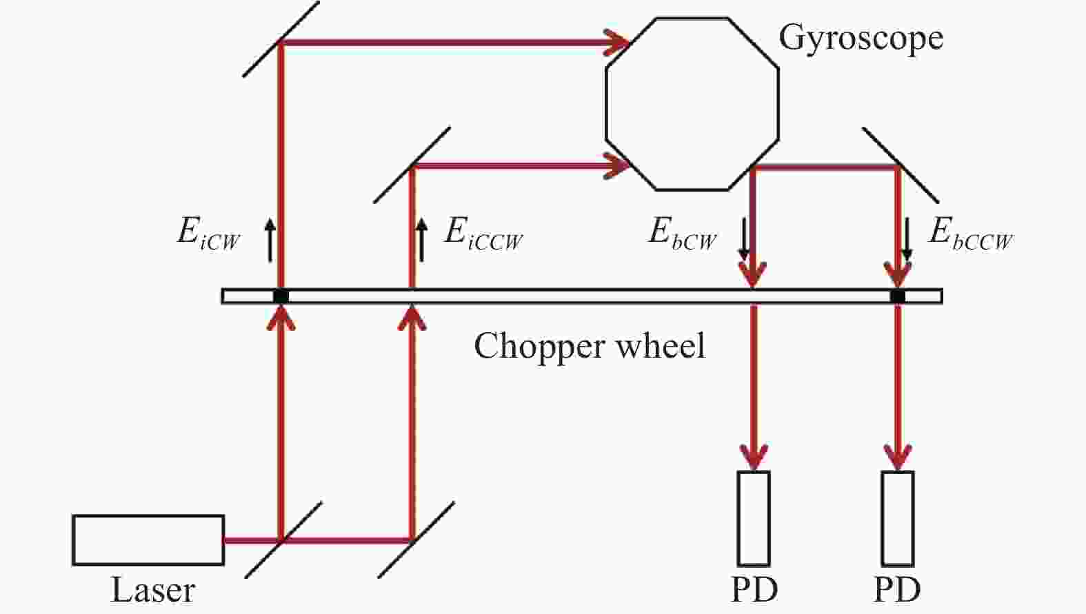
      Figure 1.  Measurement system for backscattering of ring laser resonator[10]

      式中:ΩL表示激光陀螺的闭锁阈值;IbIs分别表示背向散射光束和信号光束的光强;α表示谐振腔的损耗;c表示光速;S表示激光陀螺的比例因子;L表示谐振腔的腔长。根据上式,激光陀螺锁区的主要参数除了陀螺基本结构和特性影响外,还受制于环形谐振腔内的背向散射光束强度。测量背向散射,能够为陀螺锁区预测提供基本条件。该技术方案的核心思想是利用调制解调原理,周期性地测量环形谐振腔内顺、逆时针方向的背向散射光强。

      2012年,樊振方等人针对无源腔直接测量背向散射的方法无法有效估计腔内的非均匀损耗,亦不能反映有源腔工作状态下的背向散射等问题,提出了一种在线背向散射估计方法。通过测量不同角速度下陀螺光强信号的调制,并使用曲线拟合获得其结果,其中针对四边形陀螺开展的实验测试,得到该实验陀螺的背向散射振幅系数为10−7量级,其在频率表示下锁区大小位于430 Hz左右[11]。这项研究对环形激光陀螺仪的性能评估有一定的参考价值,可以作为降低锁区阈值和进一步提高环形激光陀螺仪性能的指导。

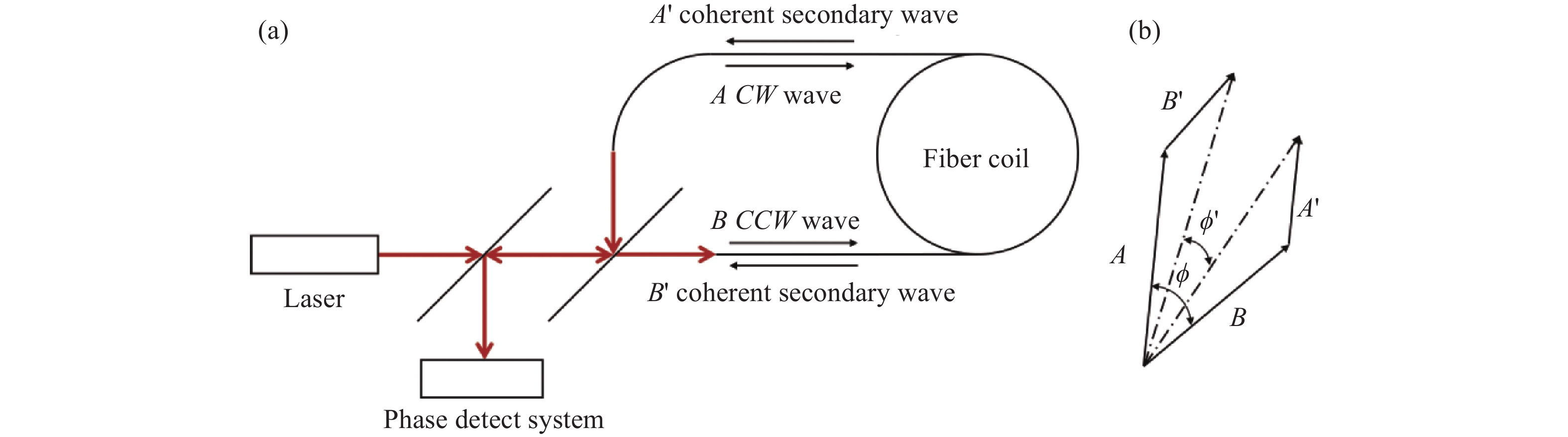
      而对于谐振式光纤陀螺,Iwatsuki K等人早在1986年就研究了其背向散射信号的谐振特性,并给出了一种测量方式[12-13],如图2 (a) 所示。其中,信号光束以顺时针方向在光纤环中传播后进入探测器1,而背散光束在光纤环末端产生后,逆时针传播进入探测器2。通过测量,证实了在谐振式光纤陀螺之中背散光束同信号光束一样存在谐振特性,并在外界转动信号输入的情况下,背散信号会发生谐振峰分离的现象,如图2 (b) 所示。该实验成功验证了谐振式光纤陀螺中背向散射的理论基础,能够为后续抑制背散噪声的方案提供一种分析手段。

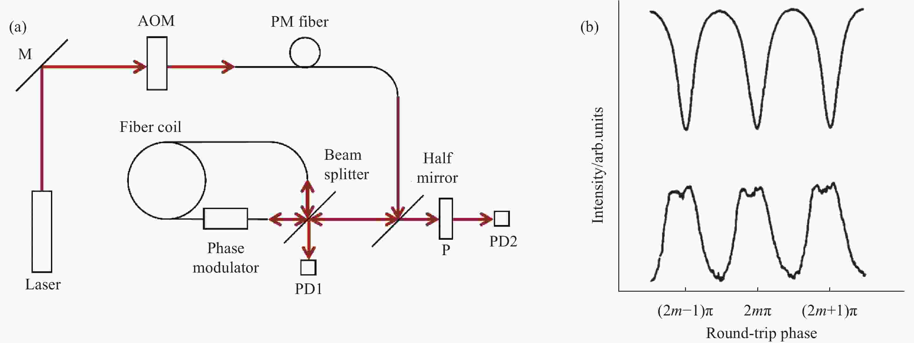
      Figure 2.  (a) Measurement system for backscattering characteristics of resonator fiber optic gyro; (b) Measuring result of backscattering characteristics of resonator fiber optic gyro[12] (AOM: Acoustic optical modulator)

      面向微光陀螺,2009年马慧莲等人提出了一种测量硅基平面光波导的环形谐振腔背向散射的方法[14],如图3 (a) 所示,系统通过信号发生器产生的锯齿波调制电压,控制激光器扫描谐振腔的谐振频率,信号光束顺时针传播后进入探测器1;而谐振腔产生的背散光束逆时针传播后进入探测器2,其测量结果如图3 (b) 所示。不难看出,这种针对波导环形谐振腔的测量方法与谐振式光纤陀螺从本质上都是利用器件将信号光束与背散光束分离开来,通过不同的探测器对其进行测量分析。得益于光纤技术的发展,测量系统相较过往更加集成紧凑,同时避免了分立光学元件的使用,尽可能降低了外界环境对测量结果的影响。

      Figure 3.  (a) Measurement system for backscattering of ring resonator in silica planar lightwave circuit; (b) Measurement result of backscattering of ring resonator in silica planar lightwave circuit[14]

      综上所述,可以看出光学陀螺中背向散射的测量,多是通过设计光路使得正向的信号光束与反向的背散光束在空间上进行分离来实现;通过分别测量其光束特性,以此来分析陀螺腔中的背向散射特性。相较而言,无源腔的背向散射测量难度要比有源腔大很多,因为无源谐振腔测量时通常需要解决外部注入光在腔内的稳定谐振问题。尤其是针对超低损耗的情况,实现窄线宽激光在其内部的稳定谐振难度较大。

    • 从宏观上来看,光学陀螺中的背向散射来源于折射率的非均匀性,但对于不同的陀螺类型,由于其核心传感元件环形腔的差异,其背向散射的表现机制也往往并不相同,这就带来了其各自的技术路线与抑制手段。下面针对几种典型的光学陀螺背向散射问题及其应对方法进行综述。

    • 激光陀螺,其本质上是一台环形激光器,利用萨格纳克效应测量外界转动引起的激光谐振频率变化,以此来实现角度感知。由于增益介质的存在,以及各种光学元件之间的差异,带来了谐振腔中折射率的非均匀性,当输入激光陀螺的外界转速信号过小时,会出现闭锁现象,即无法输出相应的正/反向光束频差,由自洽方程可以计算出正常运转条件下激光陀螺频差理论值[6]

      式中:$ \dot{\phi } $和$ \phi $为正/反向行波的频率差和相位差;Ω01Ω02为空腔正/反向行波的频率;I01I02为正/反向行波的无量纲光强;σ1σ2为频率牵引系数;ρ1、ρ2为频率自推斥系数;τ12τ21为频率互推斥系数;r1r2为复合振幅反射系数;ε为反射带来的相位变化;c为光速;<L>为环形谐振腔的平均光程。值得注意的是,空腔正/反向行波因转动产生的频差可表示为:

      式中:A表示环形谐振腔围成的面积;λ表示光的波长;Ωr表示外界的转动速度。从公式(13)可以看出,除去正/反向行波之间的频率牵引与推斥,当外界的转速Ωr逐渐减小时,空腔正/反向行波之间的频差Ω02Ω01也会随着减小,但由于复合振幅反射系数r1r2的存在,当减小到一定程度时,会导致陀螺输出的反向行波频差$ \dot{\phi } $变为零,即发生闭锁。为了得到激光陀螺的信号输出,跨越锁区就显得很有必要,通常采用偏频技术实现对闭锁阈值以下的转动信号测量,目前常用的偏频方式包括:恒速偏频、机抖偏频和四频差动三种类型[15]。但从根本上来看,压缩锁区甚至消除锁区才是解决该问题的关键,而这依赖于激光陀螺中背向散射的抑制,主要可通过优化光学元件的设计与加工、调整各背向散射矢量间的相位关系来实现[16]

    • 按照工作原理的不同可以将光纤陀螺(Fiber Optic Gyro, FOG)分为三类:即干涉式光纤陀螺(Interferometric Fiber Optic Gyro, IFOG)、谐振式光纤陀螺(Resonant Fiber Optic Gyro, RFOG)、布里渊光纤陀螺(Brillouin Fiber Optic Gyro, BFOG)[17]

    • 1976年,Vali V和Shorthill R W首次利用光纤实现了环形干涉仪,如图4所示,并提出通过增加光纤缠绕的圈数能够提高干涉仪的灵敏度[18]

      Figure 4.  Fiber ring interferometer[18]

      IFOG作为一种无源干涉式光学陀螺,从本质上来说就是一个环形干涉仪,这是其区别于谐振式陀螺的最大不同,但因灵敏度的需要,IFOG往往伴随着较大长度的环形光纤回路。其基本原理是利用环形光纤回路中正/反向光束因萨格纳克效应产生的相位差,输出携带转动信号的干涉光强:

      公式(15)为萨格纳克效应的表现形式,其中,ΔL表示正/反向光束的光程差;A表示闭合环形光路围成的面积;Ωr表示转动角速度;c表示光速;$ \phi $表示正/反向光束的相位差;k表示光波的波数;λ表示光波的波长;IoIi分别表示干涉前后的光强。

      从广义上来说,IFOG中的背向散射应该包括两个部分:一是来源于光纤与器件的端面耦合处,或是光纤之间的熔融点的背向反射(Back Reflection);二是由于光纤制造工艺的限制,光纤本身的缺陷或是瑞利散射引起的背向散射(Backscattering)。值得注意的是,前者在实际测量之中并不会携带外界转动信息,但其与信号光束的相干性总会给测量结果带来不可忽略的影响[19];而后者瑞利散射不但会产生背向散射,还会存在前向散射,但由于前向散射自身的互易性,并不会给转动信号的检测带来误差因素[20]。总而言之,背向散射光束的产生会与信号光束发生寄生干涉,从而带来一个相位误差噪声,但不同的生成方式仍然存在些许差异,对于背向反射来说,其产生的反向光束相对IFOG呈准对称分布,而背向散射则往往呈现随机分布[21]。以随机分布的背向散射噪声为例,其产生机制可以进行如下的简单阐述[21]:假设环形光纤回路中正/反向信号光束E的振幅相等均为E0,背向散射产生的光束Ebs振幅也因此相等均为Eb,由于背散光束在环形光纤回路中形成的闭合光路面积为零,其不携带转动信息,因此可以将这些光束表示为:

      式中:$ {\phi }_{0} $表示正/反向信号光束在环形光纤回路中的累积相位;$ {\phi }_{b} $,$ {\phi {'}}_{b} $分别表示正/反向背散光束在环形光纤回路中形成的不同累积相位;$ \phi $表示外界转动信号形成的萨格纳克相位差。由于$ {\phi }_{b} $,$ {\phi {'}}_{b} $的不确定性,最终探测器测量得到的相位与实际表征转动的相位$ \phi $之间将存在偏差。计算探测器接收到的光强信号,即:

      其中的相位误差噪声$ {\phi }_{error} $可以表示为:

      从公式(20)可以看到,相位误差噪声的实际取值取决于信号光束E与背散光束Ebs之间振幅的相对大小。1980年,Cutler C C等人结合背散光强与信号光强之间比值的经验公式,对背散噪声相位进行了估计,其实验系统框架如图5 (a) 所示,从图5 (b) 可以看到实际测量相位$ \phi {'} $与理论转动相位$ \phi $之间存在偏差,在角速度的表示下,测量误差在340 (°)/h左右[20]。不难发现,抑制背散光束参与干涉的振幅大小,是IFOG减小背向散射噪声的有效技术手段,通常来说主要包括两种方法:一是采用宽光谱光源;二是利用相位调制。这两种抑制方法分别侧重不同的方面,前者是从物理上控制背散光束与信号光束之间的干涉,由于宽光谱光源的低相干长度,使得环形光纤回路中只有较小的空间范围会引入误差干涉;而后者则是从信号处理的方式上降低误差干涉对系统输出的影响,从下文可以看到,这种思想在所有的FOG系统中均有体现,通过调制解调的方法,回避背向散射给陀螺带来的误差,但随着精度要求的提升,不可避免地使得整个陀螺系统更加庞大复杂。

      Figure 5.  (a) Backscattering in IFOG; (b) Phase error due to backscattering in IFOG[20]

      对于IFOG来说,相位调制的方法在一开始被提出是为了解决陀螺工作点灵敏度低以及光源电路抖动的问题[22]。后来Böhm K等人在此基础上系统地阐述了这两种减小背向散射噪声的方法:一是利用图6所示的相位调制器1以及锁相放大器,采用正弦调制使得系统工作点位于灵敏度最大处,而后通过相位调制器2引入限带噪声调制,来减弱背散光束与信号光束相互干涉带来的相位噪声;二是采取宽光谱光源,以此来减小能够产生背向散射噪声的光纤区域,理论计算可知:宽带光源的使用能够将测量误差降低一个量级[23]。值得注意的是,利用本征偏置的方波进行调制在理想情况下可以完全消除瑞利背向散射带来的相位误差[21]

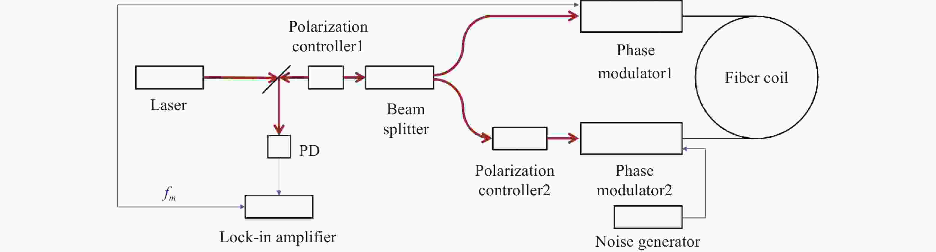
      Figure 6.  Optical structure of IFOG[23]

      为了实现更加优越的陀螺性能,相位调制器所带来的附加背向散射也被作为系统的噪声源加以研究,针对这一问题,Sanghadasa M等人从电光聚合物这一基本材料出发,设计了具备背向散射补偿机制的相位调制器,其基本结构如图7所示。通过控制相位调制器中波导两臂臂长的偏离量,来抑制背散光束之间的干涉,从而实现对背向散射的补偿。将其运用在IFOG上,相较普通对称结构的相位调制器,在6 min内的平均零偏稳定性下降为原来的五分之一[24]

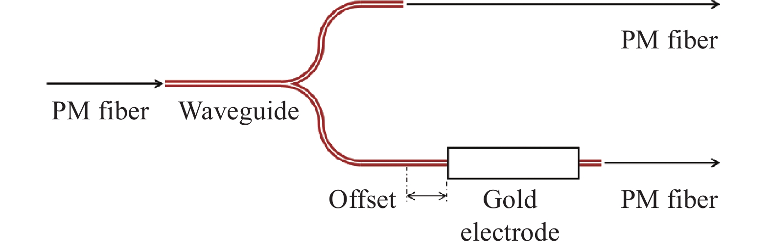
      Figure 7.  Structure of asymmetric phase modulator[24]

      随着光纤技术的发展,新兴光子晶体光纤的出现有效抑制了IFOG中的克尔效应以及Shupe效应,但相较传统保偏光纤,空芯光子晶体光纤除了背向散射,还存在些许不同的相位噪声机制。2010年,Lloyd Seth W等人利用IFOG,选择宽带光纤光源或激光光源作为系统激励,并采取普通光纤或空芯光纤制备的光纤环形线圈进行传感,从实验上测量到在激光光源与空芯光纤组合下的IFOG系统的背散相位噪声大于理论计算结果,这说明了在空芯光纤中的噪声相位来源于其他产生机制,并推测可能是由于光纤环形线圈内空芯光纤与实芯光纤交界面的相干反射[25]。Teng Fei等人在2016年利用光时域反射仪对光子晶体光纤进行了进一步的研究。通过将保偏光纤与保偏光子晶体光纤、空芯光子晶体光纤相熔接,搭建了如图8 (a)所示的实验系统,结果如图8(b) 、图8(c) 所示,可以观察到在熔接点处存在强烈的背向反射,并且从曲线斜率上来看,空芯光子晶体光纤的背向散射强度大于保偏光子晶体光纤与保偏光纤,与此同时,利用这三种光纤搭建的IFOG系统的测试结果表明,对于空芯光子晶体光纤来说背向反射光与背向散射光是带来偏置噪声的主要因素[26]

      Figure 8.  (a) Measurement system of photonic crystal fiber; (b) Measurement result of hollow-core photonic crystal fiber; (c) Measurement result of polarization-maintaining photonic crystal fiber [26] (OTDR: Optical time domain reflectometry, PMF:Polarization maintaining fiber, PM-PCF: Polarization maintaining photonic crystal fiber, HC-PCF: Hollow core photonic crystal fiber)

      除了相位调制器以及环形光纤线圈带来的误差干扰,IFOG系统中宽谱光源引入的相对强度噪声也是影响陀螺灵敏度的噪声源。所谓相对强度噪声是探测器上接收到不同光谱分量的跳动,针对这一问题,Suo Xinxin等人在2021年利用半导体光放大器对其进行抑制,最终实现的探测结果相较运用普通宽谱光源的IFOG系统角随机游走下降了31.5%[27]

      综上所述,在IFOG系统中,背向散射对陀螺的不良影响主要是通过宽谱光源以及信号调制的方式进行克服,但随着对陀螺精度要求的不断提高,技术重点不再停留于环形光纤线圈中的背向散射抑制,而是对IFOG系统进行整体评估,譬如针对相位调制器以及宽谱光源带来的寄生噪声采取进一步抑制手段,除此之外,重新评估新型光纤材料引入的背向散射噪声对优化系统性能也显得很有必要。

    • 在IFOG出现以后,由于光纤环形线圈的长度问题,学者们朝着另一种实现角度传感的技术路线进行研究。1977年,Balsamo S R和Ezekiel S提出了无源谐振式激光陀螺的模型[28],随后针对无源谐振式激光陀螺模型中谐振腔依赖于反射镜相对位置的对准问题,Shupe D M于1981年提出了利用单模光纤制成谐振环,从而实现RFOG,如图9所示,并从理论上证明:在相同量级的转动敏感度下,RFOG的传感光纤长度远小于IFOG[29]

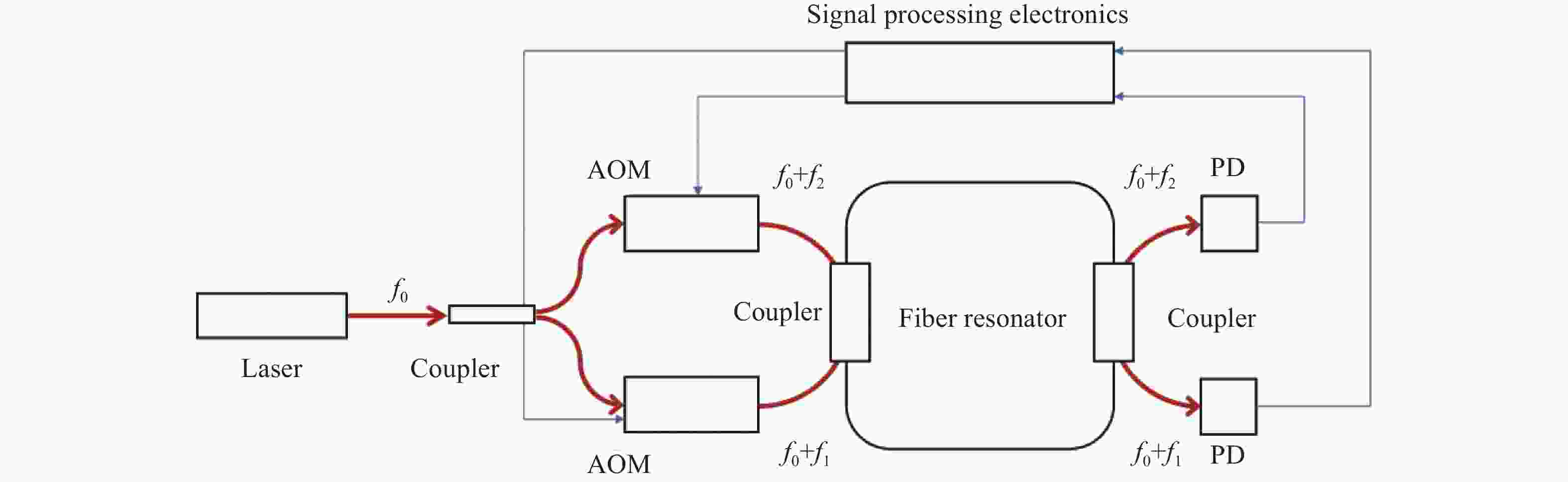
      Figure 9.  Optical path structure of RFOG[29]

      RFOG是一种无源谐振式光学陀螺,不同于IFOG,其产生萨格纳克效应的核心元件是光纤环形谐振腔(Fiber Ring Resonator, FRR),在谐振条件下,通过测量正/反向光束的频差来获得转动信号[30]

      式中:Δν表示正/反向光束的频差;L表示FRR的长度;λ表示光波的波长;其他变量定义同公式(15)。得益于FRR的运用,RFOG相较IFOG能够有效减少传感光纤的长度,但无论是FRR或是光纤环形线圈,光纤的普遍性质使得RFOG同IFOG一样,存在光纤缺陷以及瑞利散射带来的背向散射问题。1984年,Iwastsuki K等人指明了RFOG中的背向散射来源主要包括两大方面:一是FRR光纤中的瑞利散射;二是FRR光纤自身的杂质与缺陷,并针对瑞利散射进行了主要的分析[31-32]。根据同一探测器测量得到的光强信号可以分为三个主要部分:即信号光束的光强、背散光束的光强、信号光束与背散光束之间的干涉光强,其中后面两个部分为RFOG中的两类背向散射噪声。

      图10中,I1为信号光束光强;<I3>为背散光束平均光强;σ为信号光束与背散光束的干涉光强。从图10(a)可以观察到,背散光束自身以及信号光束与背散光束之间的干涉也同信号光束一样存在谐振特征。值得注意的是,这种现象可以通过一种唯像的方式进行理解,即信号光束进入环形谐振腔之后,于腔内多次传播直至离开环形谐振腔,在这个过程之中可能发生背向散射,产生传播相反方向的散射光束,同信号光束一样其也在腔内多次传播直至离开环形谐振腔,因此,背散光束应该同时具备腔内两个传播方向上的谐振特性。当外界输入转动信号时,背散光束的光强信号因萨格纳克效应会产生分离,从而形成两个谐振峰,并且其中一个谐振峰将会和一个方向上的信号光束谐振峰发生重合,如图10(b) 所示。此时,相对信号光束的谐振点来说,背散光束是不对称的,因此信号光束与背散光束之间的干涉光强信号的轮廓会发生改变,也呈现不对称的结构。

      Figure 10.  (a) Two main types of backscattering noise in RFOG; (b) Separation of intensity resonant peaks of backscattering beam in RFOG when rotate[31]

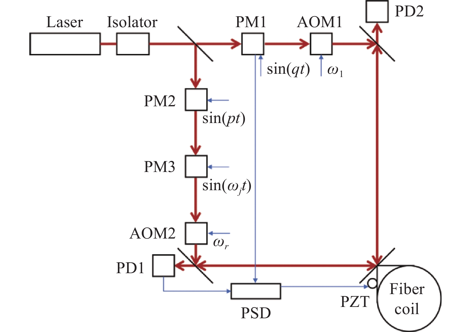
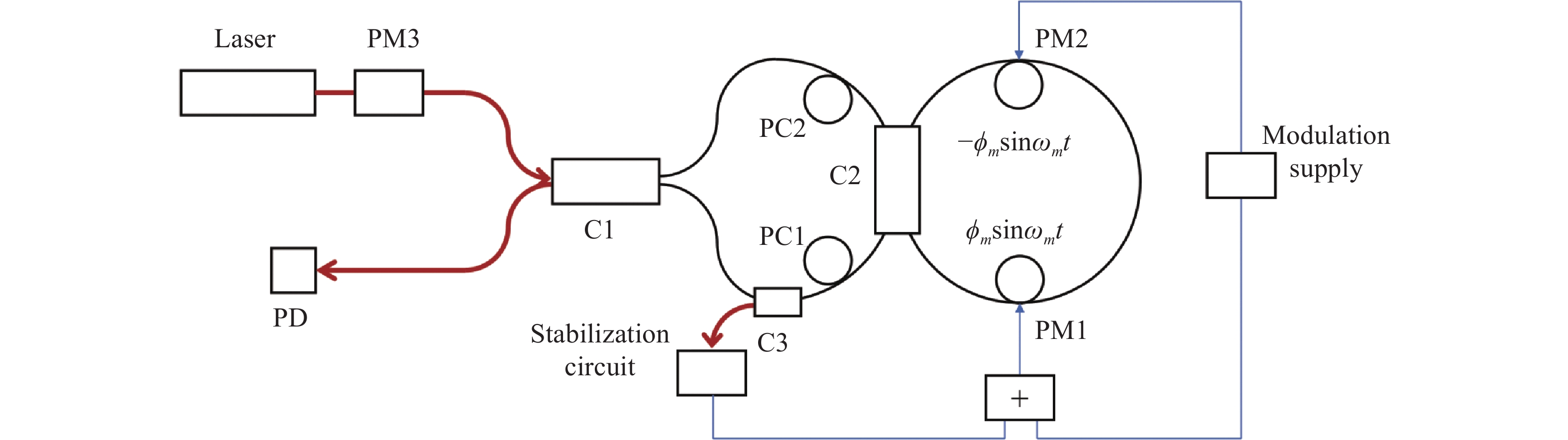
      第一类背向散射噪声,即背散光束的光强,将对RFOG谐振工作点的选取造成一定的影响,从而使得转动信号与输出频差之间的线性度下降,而且在低转速下,线性度的下降程度由信号光束强度与背散光束强度的比值决定,这种下降可以通过在入射光路中对两束信号光束进行频率或相位调制进行克服;第二类背向散射噪声,即信号光束与背散光束之间的干涉光强,会在特定转速范围内,通过反馈回路给RFOG带来噪声影响。可以在入射光路中进行相位调制,或是引入长光纤,抑或是使用两种不同激光器来减弱或消除其影响。利用相位调制抑制背向散射噪声的RFOG光路结构如图11所示,通过相位调制器在入射光路中对信号光束进行不同频率的相位调制,从而尽可能减小背散噪声。除此之外,采用压电陶瓷来控制系统工作在谐振腔的谐振频率上,进而减小频率漂移带来的不良影响。

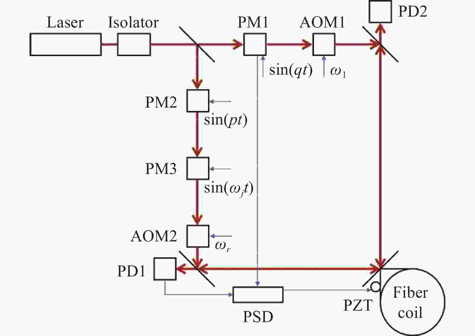
      Figure 11.  Optical path structure of RFOG to eliminate backscattering noise[31] (PM: Phase modulator, AOM: Acoustic optical modulator, PSD: Phase sensitive demodulator, PZT: Piezoelectric transducer)

      值得注意的是,从理论上分析二次背向散射的存在也会带来与第一类背向散射类似的输出线性下降[33];而对于第二类背向散射噪声,Kaiser T J等人于1991年根据散射源与FRR的相对位置采取了进一步分类,并给出了RFOG因散射带来的角速度测量误差的经验公式:

      式中:BIAS表示测量误差;c表示光速;λ表示光波波长;σR表示FRR的背散系数;D表示FRR的直径;L表示谐振腔的长度;N表示抑制载波的数目;V表示抑制载波的电压;ΔV表示抑制载波的电压误差。可以估计在RFOG中背向散射带来的角速度误差达到了15000 (°)/h,而采取一次相位调制抑制载波可以将角速度误差压缩为原来的1%,即150 (°)/h[34]

      针对背向散射带来的频率漂移,即第二类背向散射噪声,大部分研究都是采取相位调制的方式削弱其带来的影响[35-36],1986年,Zarinetchi F与Ezekiel S讨论了在闭环条件下,倘若不采取措施抑制背向散射带来的频率漂移,无源谐振陀螺也会出现类似有源谐振陀螺的锁定现象,这是由于闭环回路误将噪声频率作为反馈信号,使得低转速下没有频差输出[37],在此之后,利用克尔效应[38]、二进制相移键控[39]等进行调制的方法也被相继提出。而在实际RFOG系统之中,需要合理确定调制的最优参数,以此来同时实现对两类背向散射噪声的有效抑制[40]

      为了进一步提高对第二类背向散射噪声的载波抑制比,Liu Ning等人采取边带锁定的方法,其基本思路是利用谐振腔的滤波特性,通过将边带的频率锁定在谐振腔的谐振频率上,相较传统载波抑制将载波的频率进行锁定,这种方法能够获取更高的载波抑制比[41];与此同时,Jiao Hongchen等人还提出了利用多频差分的方法,降低外界温度等环境因素对调制深度的影响,实现更加稳定的载波抑制[42];在此基础上,结合两种方法,最终实现117 dB的载波抑制比[43]

      除此之外,采用不同激光器降低背向散射噪声的方案也被提出,如图12所示,Wu Jianfeng等人利用三个不同的激光器,通过光学锁相环将两个从激光器锁定到一个主激光器上,并令两个从激光器的频率间隔一个谐振腔的自由光谱范围,以此来抑制背散光束与信号光束之间的相互干涉[44]。而着眼于不同相位调制器带来的残余幅度调制,例如系统中的二次谐波失真或是强度调制, 同样来自Honeywell公司的Strandjord L K等人在相位锁定激光的RFOG系统上引入了第三个相位调制器对两束激光进行共同相位调制,尽可能减小两束光路中由于相位调制器不同带来的调制缺陷[45]

      Figure 12.  Optical path structure of RFOG using phase-locked lasers[44] (OPLL: Optical phase lock-loop, PM: Phase modulator, IM: Intensity modulator)

      针对普通单光源RFOG系统中的残余幅度调制问题,2020年Li Hanzhao等人利用相同的方式引入共同相位调制解调,实现了0.06 (°)/h的零偏稳定性[46]。在此基础上,Zou Kang等人针对共同相位调制的RFOG系统中的调制参数提出了一种优化方法,相较普通的参数选择方式探测灵敏度提升了19%[47]。值得注意的是,共同相位调制方式的引入确实解决了残余幅度调制噪声,但同时使得无法通过调制解调的方法滤除第一类背向散射噪声对系统的影响。针对这一问题,Liu Lu等人提出运用相干探测来解决这两种噪声,其系统如图13所示。通过声光移频器的引入,并将经过谐振腔的正/反信号光与正/反参照光进行干涉,利用带通滤波能够有效滤除第一类背向散射噪声的影响,并最终获得1.23 (°)/h的零偏稳定性[48]

      Figure 13.  Optical path structure of RFOG using coherent detection[48] (C: Coupler, PM: Phase modulator, AOM: Acoustic optical modulator, TA: Tunable attenuator, BPF: Bandpass filter, LPF: Low-pass filter)

      可以看到为了抑制背向散射噪声,RFOG的系统结构相较IFOG来说变得更加复杂,更多调制器件的引入也给系统带来了更多的寄生噪声。对此,2022年Zhao Shuangxiang等人提出利用宽谱白光光源来实现RFOG,其光路结构如图14(a) 所示,可以看到其大致结构类似IFOG,其最大的不同是传感核心元件仍然同RFOG一样采取谐振腔,得益于宽谱光源的使用,避免了庞杂的调制器件的引入,使得系统结构较为简单。类似IFOG,其探测的是正/反方向上两束谐振光束的干涉光强信号,当外界存在转动时,光强信号将发生变化如图14(b) 所示,随着外界转动信号的增大,探测器上接收到的光强信号随之减小,最终在35000 s内得到了0.009 (°)/h的零偏稳定性[49]

      在RFOG抑制背向散射的技术手段中大部分着眼于相位调制以及光源选取上:对于相位调制来说,第一类背散噪声往往是通过信号频率的差异进行滤除,而第二类背散噪声的削减效果则取决于相位调制方案或参数的选取对载波抑制效率的影响;对于多个激光光源实现的RFOG对于第一类背散噪声的处理方式与相位调制大同小异,而由于多个激光频率的不同使得背散光束与信号光束之间的干涉能够被有效抑制,从而削减第二类背散噪声;值得注意的是,宽谱光源搭建的类IFOG系统避免了复杂调制器件的使用,能够避免冗杂的寄生噪声,在实现系统精简集成具有一定的前景。

      Figure 14.  (a) Optical path structure of RFOG using broadband source; (b) Measurement result of RFOG using broadband source[49] (MIOC: Multifunction integrated-optics chip)

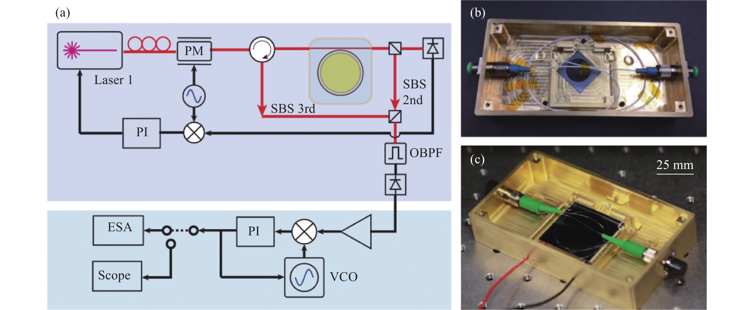
    • 对于IFOG,RFOG来说,受激布里渊散射同背向散射一样属于一种影响陀螺输出的噪声源,但从另一个角度来讲,受激布里渊散射激光的频移性质与反向传播特性使得构建BFOG存在可能。1976年,Hill K O等人首次在FRR中观测到布里渊激光现象[50];紧接着Thomas P J等人提出了利用布里渊环形激光器测量转动信号,并构建了相应的系统,如图15所示,但受限于实验条件并没有观测到正/反向光束形成的拍频现象[51]

      Figure 15.  Optical path structure of BFOG[51]

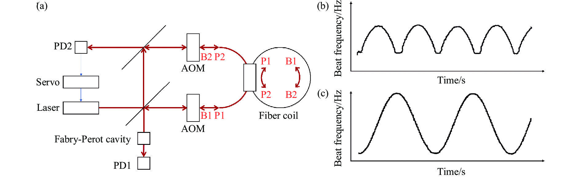
      1989年,Kadiwar R K与Giles I P成功搭建了BFOG观测到了正/反向受激布里渊散射光产生的拍频现象,以及低转速下的频率锁定效应[52]。不同于IFOG,RFOG的无源工作方式,BFOG从本质上来说是一种有源谐振式光学陀螺,即激光陀螺的光纤化。得益于受激布里渊散射增益的方向敏感性,外界泵浦光源输入FRR中的正/反向泵浦光能够产生传输方向相反的布里渊散射激光,通过测量正/反向散射光束的拍频,即能够得到外界转动信号。类似的,BFOG谐振腔中光纤折射率的非均匀性带来的瑞利背向散射,也会导致与激光陀螺相同的闭锁效应。因此,采用与激光陀螺相似的偏频方法正是跨越BFOG锁区的一种有效方法:其光路结构如图16(a)所示,通过声光调制器对正/反向泵浦光进行频率偏置,能够有效克服闭锁效应带来的影响,在相同的正弦转动信号下,采取偏频方法前后输出的拍频信号如图16(b) 、图16(c) 所示,研究同时指出BFOG中的拍频锁区大小约为1 kHz,并随着温度波动在0~3 kHz之间起伏,除此之外,背向散射的存在还会带来拍频的抖动[53]

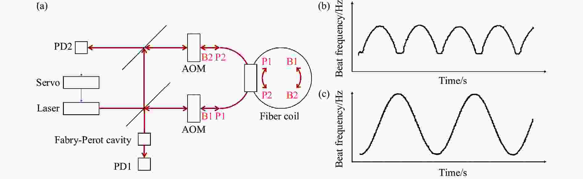
      Figure 16.  (a) Optical path structure of BFOG to remove lock-in phenomena by frequency biasing; (b) Signal beat frequency in BFOG without frequency biasing; (c) Signal beat frequency in BFOG with frequency biasing[53] (P: Pump light, B: Stimulated Brillouin scattering)

      而除了偏频的方法,对于BFOG来说,采取推挽相位调制[54]、克尔效应[55]也是减小闭锁带来陀螺性能下降的重要手段,这两种方法从根本上来说都属于一种相位调制,但不同之处在于前者是通过在谐振腔中设置压电陶瓷来实现,如图17光路结构中相位调制器引入的正/负相位调制;而后者则是在泵浦光的产生光路中引入声光调制器进行强度调控,以谐振腔中的克尔效应来实现相应的相位调制。

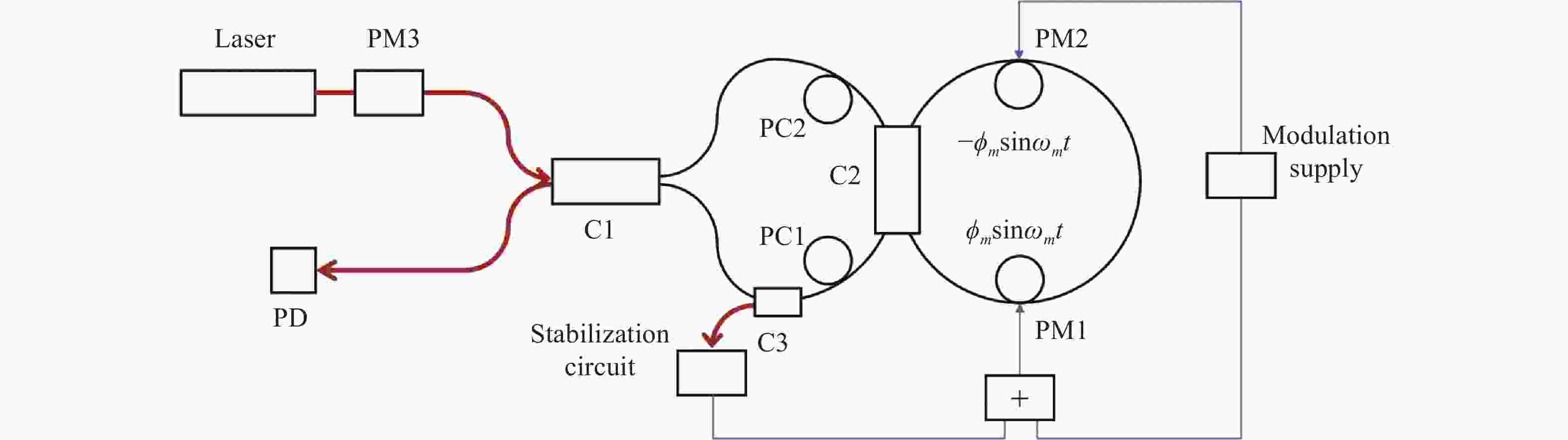
      Figure 17.  Optical path structure of BFOG to remove lock-in phenomena by push-pull phase modulation[54] (C: Coupler, PM: Phase modulator, PC: Polarization controller)

    • 随着微纳光学制造技术的发展,小尺寸、低功耗的微型光学陀螺应运而生。微型光学陀螺可以视为是RFOG与BFOG在片上集成的延续,目前发展较为成熟的方案多是基于波导型、回音壁型微环形谐振腔构建的实验系统[56]。相较于光纤谐振腔,其制造工艺更加精细,但硅基材料中折射率的不均匀性仍然会带来背向散射的不良影响。

    • 从本质上来说该类陀螺仍然是一种RFOG,克服其中的第二类背向散射噪声仍然是众多研究工作着眼的关键问题。自1980年,Northrop公司提出一种基于无源波导的薄膜激光陀螺开始[57],许多工作围绕着制造波导谐振腔进行转动传感展开[58-59]。类似于RFOG,通过相位调制进行载波抑制也是微型无源谐振陀螺中的常用方法。2000年,Suzuki K采用热光相位调制在硅基平面光波导上的微型谐振式陀螺实现了二进制相移调制,但由于其调制频率不够高,导致其载波抑制比大小只有7.6 dB[60];自2009年以来,马慧莲课题组利用LiNbO3相位调制器实现了单正弦相位调制[14]、双正弦相位调制[61],分别实现了50 s内1656 (°)/h,以及200 s内648 (°)/h的零偏稳定性,其光路结构分别如图18(a) 、图18(b) 所示;二者最大的差异在于双正弦相位调制在每一路入射光路中串联了两个不同调制参数的相位调制器,从而实现更高的载波抑制比,以此来放宽对调制器半波电压稳定度的要求;与此同时,指出在硅基平面光波导中背向散射带来的角速度误差为1.62×10⁷ (°)/h。在此之后,利用单三角波相位调制、双三角波相位调制的方法也被相继提出,分别达到了60 min内2592 (°)/h,以及60 min内792 (°)/h的零偏稳定性[62-63]

      Figure 18.  (a) Optical path structure of waveguide resonant gyro based on single sine phase modulation[14]; (b) Optical structure of waveguide resonant gyro based on double sine phase modulation[61] (C: Coupler, PM: Phase modulator, LIA: Lock-in amplifier, PI: Proportional integrator, LDC: Laser diode controller, FBC: Feedback circuit)

      除此之外,类似RFOG,采用双独立激光器抑制背散噪声的方案也在波导谐振腔上提出,其最终能够实现60 min内9.06 (°)/h的零偏稳定性[64]。同样的,宽谱光源也在波导谐振腔上得到了运用,2023年Liu Shuang等人采用多匝波导谐振腔结合宽谱光源设计了一种波导型谐振陀螺。这种陀螺结构一方面利用宽光谱光源抑制了多匝波导谐振腔带来的交叉散射现象,另一方面多匝波导谐振腔的使用能够增强系统的交叉损耗,有效降低了宽谱光源引入的相对强度噪声,并最终实现4000 s内1 (°)/h的零偏稳定性[65]

      值得注意的是,针对微球型谐振腔的背向散射问题,Xie Chengfeng等人提出了一种类似光隔离器的解决思路,如图19所示,通过在谐振腔前后设置检偏器以及法拉第旋光器,以此来改变背向散射光的偏振状态并抑制其传播,从而降低系统的背向散射噪声,利用这种结构,其最终达到1000 s内144 (°)/h的零偏稳定性[66]

      Figure 19.  Suppression of backscattering noise in microsphere resonator by Faraday rotators[66]

    • 得益于微型谐振腔的使用,受激布里渊散射的阈值相较BFOG来说有了一定的下降,这就给克服有源光学陀螺的闭锁问题带来了另一种技术手段。2017年, Li Jiang等人基于SiO2微环形谐振腔,利用二阶、三阶斯托克斯光设计了一种片上布里渊激光陀螺。如图20(a) 所示,其通过级联布里渊散射产生多级布里渊散射光,相邻级次的布里渊散射光传播方向相反,能够有效应用萨格纳克效应传感外界转动,与此同时,散射光的天然频率间隔超过了10 GHz,因此克服了传统BFOG中的闭锁效应[67]。类似的,基于Si3N4波导谐振腔,SiO2波导谐振腔设计的微型布里渊陀螺也被相继提出[68-69]。2020年,同样来自Vahala课题组的Lai Yuhung等人增大了微环形谐振腔的尺寸,研制了第二代基于SiO2微环形谐振腔的布里渊激光陀螺,并实现了对地球转动的测量,最终实现的零偏稳定性大约下降为原来六分之一[70]。从图20(b) 、图20(c) 可以观察到,两代陀螺样机虽然在传感元件上实现了集成,但受激布里渊散射的泵浦光仍然需要外界光源提供,这从一定程度上限制了整个陀螺系统的尺寸,不难看出,实现高光束质量光源的集成是此类微型布里渊激光陀螺产业化的重要发展方向。

      Figure 20.  (a) Optical path structure of Brillouin laser gyro based on SiO2 micro ring resonator; (b) First generation of micro-resonator Brillouin gyro by Vahala research group[67]; (c) Second generation of micro-resonator Brillouin gyro by Vahala research group [70]

    • 背向散射是光学陀螺中一个无法避免的现象,它会导致陀螺性能的下降甚至信号丢失、功能失效。从原理上来看,背向散射可以利用半经典理论下的自洽方程进行有效阐述,其本质上是谐振腔中宏观折射率不均匀性导致的光波相互耦合问题。

      对于不同的光学陀螺,背向散射的具体表现形式如表1所示。可以看到,闭锁效应广泛地存在于有源谐振式陀螺,随着集成化程度的提高,其锁区大小会有相应的增大,比较常用跨越锁区的手段是利用偏频与相位调制,但随着片上布里渊陀螺的出现,其自然频率偏置自发的克服了闭锁效应;而对于无源陀螺来说,背向散射更加普遍地以噪声表现出来,通常的做法即是对信号光束进行调制,尽可能降低其对测量输出的不良影响。而利用宽谱光源从根本上减小背散光束带来的误差,这不仅在干涉型光纤陀螺中得到了广泛的运用[27],目前结合光学谐振腔的宽谱光源陀螺样式也被得到发展[49, 65]

      Types of optical gyroscopesSource of backscatteringAdverse effectTypical valueInhibition method
      Laser gyroscopeInhomogeneity of media and optical elementsLock-in effectLock-in threshold:
      430 Hz[11]
      Frequency biasing
      Interferometric fiber optic gyroscopeManufacturing defects in optical fibers and waveguides, Rayleigh scatteringPhase error noiseNoise magnitude:
      340 (°)/h[20]
      Phase modulation and use of low-coherence laser
      Resonant fiber optic gyroscopeFrequency deviation noise and nonlinearity of scale factorNoise magnitude:
      15000 (°)/h[34]
      Carrier suppression
      Brilliant fiber optic gyroscopeLock-in effectLock-in threshold:
      1000 Hz[53]
      Frequency biasing and phase modulation
      Micro passive resonant gyroscopeFrequency deviation noise and nonlinearity of scale factorNoise magnitude:
      1.62×10⁷ (°)/h [14]
      Carrier suppression
      Micro Brilliant laser gyroscopeLock-in effect-Cascaded Brilliant scattering

      Table 1.  Backscattering behavior in various optical gyroscope

      目前对于不同的光学陀螺,研究内容普遍集中于利用各类调制手段,实现对背向散射不良影响的有效抑制,以期趋近陀螺的极限信噪比,但仍然存在一些尚未解决的问题:

      (1) 对光学陀螺中背向散射的微观精确测量问题。目前针对光学陀螺中的背向散射测量,更多的是着眼于谐振腔宏观上表现出来的频率漂移或是闭锁阈值,得到的多是表征背向散射的经验公式,而从微观层面上分析陀螺系统中存在的背向散射因素,对于更好地了解陀螺中行波的反向耦合机制,提升优化陀螺性能能够带来一定的帮助。遗憾的是,这部分精细研究国内外相对较少,更基础、更底层的问题还需要持续深入研究。

      (2) 如何通过合理设计加工尽可能减小光学陀螺中的背向散射量级的问题。当前许多研究工作大多是围绕着调制手段的设计而开展,但如何从根本上减小陀螺谐振腔中的非均匀性,对于普遍降低背向散射影响具有重要意义,尤其对于具有巨大前景的硅基片上光学陀螺,不可避免涉及到硅基材料的超精密加工与抛光,因此,如何优化硅基材料的加工生产手段,得到性能更加优越的谐振腔,或能从根本上提升微型片上光学陀螺的性能。

      (3) 如何巧妙利用背向散射的特性、去除其不利的方面,推动其在精密计量和测量等方面的应用问题。任何事物都有其两面性,在看到其不利性的同时,还可以研究其特性应用的可能。比如光纤/微光陀螺中的受激布里渊散射,对于普通干涉型光纤陀螺、谐振型光纤陀螺来说,布里渊散射同背向散射一样是一种噪声源,而利用该效应制成的布里渊陀螺则带来了集成化的有源谐振式陀螺,乃至在片上陀螺中自发地克服了闭锁效应的影响。光学陀螺中的背向散射也如此,如何发挥它的优点弥补其缺陷,为我所用,将是一个值得深入研究和创新的问题。

Reference (70)

Catalog

    /

    DownLoad:  Full-Size Img  PowerPoint
    Return
    Return