Volume 52 Issue 12
Dec.  2023
Turn off MathJax
Article Contents

Chao Xiangzhang, Diao Xiaofei, Kang Yanhui, Fan Xinrui, Lei Lihua, Liu Liqin. Linear constraint approach for calibrating distance of base point in laser tracking interferometer system[J]. Infrared and Laser Engineering, 2023, 52(12): 20230288. doi: 10.3788/IRLA20230288
Citation: Chao Xiangzhang, Diao Xiaofei, Kang Yanhui, Fan Xinrui, Lei Lihua, Liu Liqin. Linear constraint approach for calibrating distance of base point in laser tracking interferometer system[J]. Infrared and Laser Engineering, 2023, 52(12): 20230288. doi: 10.3788/IRLA20230288

Linear constraint approach for calibrating distance of base point in laser tracking interferometer system

doi: 10.3788/IRLA20230288
Funds:  Basic Research Foundation of National Institute of Metrology (AKYZD2109); Natural Science Foundation of Shanghai (21ZR1483100); Program of Shanghai Academic/Technology Research Leader (21XD1425000)
  • Received Date: 2023-05-07
  • Rev Recd Date: 2023-06-20
  • Accepted Date: 2023-07-03
  • Available Online: 2023-12-22
  • Publish Date: 2023-12-22
  •   Objective  To ensure the high precision of robot operations, it is imperative to calibrate the robot, enhancing its absolute positional accuracy. The most commonly employed method is the distance error model, which requires obtaining distance information between the robot's end-effector and the measurement device. While laser trackers are widely used due to their high accuracy in directly measuring the position information of the end-effector, they are general-purpose and often expensive devices with many features that go unused in the context of robot calibration. To address these concerns, a custom-designed Laser Tracking Interferometer System (LTIS) has been developed for scenarios requiring high accuracy at a lower cost. The LTIS comprises a tracker module and an interferometer module. In this system, a reference point, termed the base point, is essential for measuring absolute distances. All distances measured by the LTIS are referenced to this base point. Consequently, the accuracy of the distance from the LTIS to the base point, known as the Distance of Base Point (DBP), is crucial as it directly influences the overall accuracy of the LTIS. Designing a high-accuracy calibration method for the DBP is essential for achieving precise and cost-effective robot calibration in various applications.  Methods  The present study introduces a novel method for calibrating the Distance of Base Point (DBP) in a LTIS using a linear constraint approach. As only the DBP is needed in robot calibration, the outgoing light of the laser interferometer is employed as the x-axis to establish the coordinate system (Fig.2). The constraint points utilized for DBP calibration are situated on the line defined by the x-axis. The least square method is then applied to calculate the DBP. The optimal parameters for this calibration method are determined through a combination of theoretical analyses and simulations (Fig.3 and Fig.4). Finally, the proposed method is applied to calibrate the LTIS and obtain its DBP (Fig.5). To validate the calibration result, the DBP of the API radian tracker is calibrated and compared with the normal value (Fig.6).   Results and Discussions   The number and distribution of constraint points, as well as the layout of the calibration system, can significantly influence the calibration results, as indicated by theoretical analyses and simulations. The analysis results suggest that the constraint points used for calibration should be evenly and equidistantly distributed on the constrained line around the laser tracking system. Furthermore, the constraint points should be dispersed as widely as possible along the constrained line to ensure that the distances li measured by the LTIS exhibit noticeable differences, thereby reducing calibration errors. Optimal calibration parameters were determined through simulation experiments and actual experimental conditions. The constraint line was set to 3 400 mm, with 20 constraint points evenly and equidistantly placed on the x-axis, symmetrically positioned around the LTIS.   Conclusions  In the DBP calibration method for laser tracking interferometry based on the linear constraint approach, all constraint points used for calibration are distributed along a line. The interferometer measures the displacement of the target mirror along the linear direction to obtain the coordinate of the constraint point. Simultaneously, the LTIS measures the change in distance between the target mirror and the base point. The least squares principle is then employed to calculate the DBP. The weighted average DBP in the LTIS is found to be 290.076 4 mm, with a standard deviation of 4.4 μm. To validate this result, the DBP of an API radian laser tracker was calibrated using this method. The measured DBP of the API radian is 154.194 0 mm, with an error of 3 μm compared to the normal value. The API radian, which has an accuracy of 10 μm+5 μm/m in space, demonstrates that the linear constraint approach for calibrating the DBP in the Laser Tracking Interferometer System meets the requirements of robot calibration. This method holds significant importance for the industrial robot industry.
  • [1] 赵海鹏, 杜玉红, 丁娟, 等. 移动机器人中激光雷达测距测角标定方法[J]. 红外与激光工程, 2019, 48(06): 371-378. doi:  doi:10.3788/IRLA201948.06300020002

    Zhao Haipeng, Du Yuhong, Ding Juan, et al. LiDAR ranging angle measurement calibration method in mobile robot [J]. Infrared and Laser Engineering, 2019, 48(6): 0630002. (in Chinese) doi:  doi:10.3788/IRLA201948.06300020002
    [2] 乔贵方, 孙大林, 温秀兰, 等. 面向机器人标定的单激光跟踪仪顺序多站式测量系统建模与分析[J]. 计量学报, 2020, 41(11): 1313-1320.

    Qiao Guifang, Sun Dalin, Wen Xiulan, et al. Modeling and analysis of sequential multi-lateration measurement system based on single laser tracker for robot calibration [J]. Acta Metrologica Sinica, 2020, 41(11): 1313-1320. (in Chinese)
    [3] Li X, Zhang E, Fang X, et al. Calibration method for industrial robots based on the principle of perigon error close [J]. IEEE Access, 2022, 10: 48569-48576. doi:  10.1109/ACCESS.2022.3172505
    [4] Miao L, Zhang Y, Song Z, et al. A two-step method for kinematic parameters calibration based on complete pose measurement-verification on a heavy-duty robot [J]. Robotics and Computer-Integrated Manufacturing, 2023, 83: 102550. doi:  https://doi.org/10.1016/j.rcim.2023.102550
    [5] 杜 亮, 张 铁, 戴孝亮, 等. 激光跟踪仪测量距离误差的机器人运动学参数补偿[J]. 红外与激光工程, 2015, 44(8): 2352-2357.

    Du Liang, Zhang Tie, Dai Xiaoliang, et al. Robot kinematic parameters compensation by measuring distance error using laser tracker system [J]. Infrared and Laser Engineering, 2015, 44(8): 2352-2357. (in Chinese)
    [6] 陈相君, 古力那尔·祖农, 薛梓, 等. 基于激光跟踪仪的协作机器人标定算法与实验研究[J]. 计量学报, 2021, 42(5): 552-557.

    Chen Xiangjun, Gulinaer Zunong, Xue Zi, et al. Calibration algorithm and experimental research of cooperative robot based on laser tracker [J]. Acta Metrologica Sinica, 2021, 42(5): 552-557. (in Chinese)
    [7] 邢运隆, 李论. 一种基于指数积的机械臂结构参数标定方法[J]. 制造业自动化, 2023, 45(02): 12-16+29.

    Xing Yunlong, Li Lun. A calibration method of mechanical arm structure parameters based on exponential product [J]. Manufacturing Automation, 2023, 45(2): 12-16, 29. (in Chinese)
    [8] 何俊, 张福民, 张画迪, 等. 基于球心拟合的多边激光跟踪系统自标定方法[J]. 红外与激光工程, 2020, 49(8): 201904381-201904387.

    He Jun, Zhang Fumin, Zhang Huadi, et al. Multilateral laser tracking system self-calibration method based on spherical center fitting [J]. Infrared and Laser Engineering, 2020, 49(8): 201904381. (in Chinese)
    [9] 刘健, 刘巍伟, 臧延旭. 基于激光测量技术的远距离目标高精度跟踪研究[J]. 激光杂志, 2021, 42(11): 60-64.

    Liu Jian, Liu Weiwei, Zang Yanxu. High precision tracking of long-distance target based laser measurement technology [J]. Laser Journal, 2021, 42(11): 60-64. (in Chinese)
    [10] 平少栋, 傅云霞, 张丰, 等. 镜面反射式激光跟踪干涉测长的测量方法研究[J]. 红外与激光工程. 2021, 50(12): 403-409. doi:  10.3788/IRLA20210624

    Ping Shaodong, Fu Yunxia, Zhang Feng, et al. Study on measurement method of mirror reflection laser tracking interferometric length measurement [J]. Infrared and Laser Engineering, 2021, 50(12): 20210624. (in Chinese) doi:  10.3788/IRLA20210624
    [11] Zhuang H, Motaghedi S H, Roth Z, et al. Calibration of multi-beam laser tracking systems [J]. Robotics and Computer Integrated Manufacturing, 2003, 19(4): 301-314. doi:  10.1016/S0736-5845(02)00076-5
    [12] Motaghedi S H. Self-calibration of laser tracking measurement system with planar constraints[D] Florida: College of Engineering, Florida Atlantic University, 1999.
    [13] 张亚娟. 单站式激光跟踪坐标测量系统研究[D]. 天津: 天津大学, 2012.

    Zhang Yajuan. Stand alone laser tracking system[D]. Tianjin: Tianjin University, 2012. (in Chinese)
    [14] Zhang Yajuan, Qiu Zurong, Li Xinghua, et al. Calibration of laser tracking system with spherical constraint [J]. Journal of Tianjin University (Science and Technology), 2014, 47(3): 255-261. (in Chinese)
    [15] 李杏华. 激光跟踪系统的设计[D]. 天津: 天津大学, 2003.

    Li Xinghua. Design of a laser tracking system[D]. Tianjin: Tianjin University, 2003. (in Chinese)
    [16] 周春艳. 激光跟踪坐标测量系统的双线法基点自标定[J]. 科学技术与工程, 2009, 9(12): 3429-3431.

    Zhou Chunyan. Double line of base point self calibration in laser tracking coordinate measuring system [J]. Science Technology and Engineering, 2009, 9(12): 3429-3431. (in Chinese)
    [17] 许航, 熊芝, 张刘港, 等. 基于加权最小二乘的激光跟踪姿态角测量方法[J]. 红外与激光工程, 2022, 51(6): 20210675. doi:  10.3788/IRLA20210675

    Xu Hang, Xiong Zhi, Zhang Liugang, et al. Laser tracking attitude angle measurement method based on weighted least squares [J]. Infrared and Laser Engineering, 2022, 51(6): 20210675. (in Chinese) doi:  10.3788/IRLA20210675
  • 加载中
通讯作者: 陈斌, bchen63@163.com
  • 1. 

    沈阳化工大学材料科学与工程学院 沈阳 110142

  1. 本站搜索
  2. 百度学术搜索
  3. 万方数据库搜索
  4. CNKI搜索

Figures(6)  / Tables(4)

Article Metrics

Article views(65) PDF downloads(21) Cited by()

Related
Proportional views

Linear constraint approach for calibrating distance of base point in laser tracking interferometer system

doi: 10.3788/IRLA20230288
  • 1. Division of Dimensional Metrology, National Institute of Metrology, Beijing 100029, China
  • 2. Institute of Ultra-precision Optoelectronic Instrument Engineering, Harbin Institute of Technology, Harbin 150080, China
  • 3. Shanghai Key Laboratory of Online Test and Control Technology, Shanghai 201203, China
Fund Project:  Basic Research Foundation of National Institute of Metrology (AKYZD2109); Natural Science Foundation of Shanghai (21ZR1483100); Program of Shanghai Academic/Technology Research Leader (21XD1425000)

Abstract:   Objective  To ensure the high precision of robot operations, it is imperative to calibrate the robot, enhancing its absolute positional accuracy. The most commonly employed method is the distance error model, which requires obtaining distance information between the robot's end-effector and the measurement device. While laser trackers are widely used due to their high accuracy in directly measuring the position information of the end-effector, they are general-purpose and often expensive devices with many features that go unused in the context of robot calibration. To address these concerns, a custom-designed Laser Tracking Interferometer System (LTIS) has been developed for scenarios requiring high accuracy at a lower cost. The LTIS comprises a tracker module and an interferometer module. In this system, a reference point, termed the base point, is essential for measuring absolute distances. All distances measured by the LTIS are referenced to this base point. Consequently, the accuracy of the distance from the LTIS to the base point, known as the Distance of Base Point (DBP), is crucial as it directly influences the overall accuracy of the LTIS. Designing a high-accuracy calibration method for the DBP is essential for achieving precise and cost-effective robot calibration in various applications.  Methods  The present study introduces a novel method for calibrating the Distance of Base Point (DBP) in a LTIS using a linear constraint approach. As only the DBP is needed in robot calibration, the outgoing light of the laser interferometer is employed as the x-axis to establish the coordinate system (Fig.2). The constraint points utilized for DBP calibration are situated on the line defined by the x-axis. The least square method is then applied to calculate the DBP. The optimal parameters for this calibration method are determined through a combination of theoretical analyses and simulations (Fig.3 and Fig.4). Finally, the proposed method is applied to calibrate the LTIS and obtain its DBP (Fig.5). To validate the calibration result, the DBP of the API radian tracker is calibrated and compared with the normal value (Fig.6).   Results and Discussions   The number and distribution of constraint points, as well as the layout of the calibration system, can significantly influence the calibration results, as indicated by theoretical analyses and simulations. The analysis results suggest that the constraint points used for calibration should be evenly and equidistantly distributed on the constrained line around the laser tracking system. Furthermore, the constraint points should be dispersed as widely as possible along the constrained line to ensure that the distances li measured by the LTIS exhibit noticeable differences, thereby reducing calibration errors. Optimal calibration parameters were determined through simulation experiments and actual experimental conditions. The constraint line was set to 3 400 mm, with 20 constraint points evenly and equidistantly placed on the x-axis, symmetrically positioned around the LTIS.   Conclusions  In the DBP calibration method for laser tracking interferometry based on the linear constraint approach, all constraint points used for calibration are distributed along a line. The interferometer measures the displacement of the target mirror along the linear direction to obtain the coordinate of the constraint point. Simultaneously, the LTIS measures the change in distance between the target mirror and the base point. The least squares principle is then employed to calculate the DBP. The weighted average DBP in the LTIS is found to be 290.076 4 mm, with a standard deviation of 4.4 μm. To validate this result, the DBP of an API radian laser tracker was calibrated using this method. The measured DBP of the API radian is 154.194 0 mm, with an error of 3 μm compared to the normal value. The API radian, which has an accuracy of 10 μm+5 μm/m in space, demonstrates that the linear constraint approach for calibrating the DBP in the Laser Tracking Interferometer System meets the requirements of robot calibration. This method holds significant importance for the industrial robot industry.

    • 工业机器人在现代社会中的应用越来越广泛,在汽车制造、航空航天、医疗卫生等领域都有着举足轻重的地位[1-4];医用机器人的绝对定位精度在亚毫米级别,某些场合中装配机器人的绝对定位精度要达到0.01 mm以下,然而由于工业机器人在生产制造过程中存在加工误差及装配误差,在未经标定的情况下其绝对定位精度一般在0.5~10 mm。因此需要对机器人的DH参数进行标定,使其能够达到与其任务相匹配的精度水平。

      在基于距离误差模型的工业机器人DH参数标定工作中,需要获取机器人末端到测量设备的绝对距离。现阶段,往往使用激光跟踪仪进行测量工作[5-7],然而激光跟踪仪作为通用测量设备,其功能齐全、操作复杂、价格昂贵,因此亟需一种低成本、操作简单的高精度机器人标定专用设备。目前,国内外学者主要使用激光干涉跟踪测量技术[8-10]进行高精度测量,采用干涉测量技术对机器人的DH参数误差进行标定。在测量过程中需要一个基点来实现绝对距离测量,基点与干涉测量设备的距离称为基点距离。

      为了准确地测量出基点距离,美国佛罗里达大西洋大学的Motaghedi S H设计了约束平面法来求解基点坐标[11-12],但是难以获得高精度的约束平面制约了平面约束方法的标定精度;天津大学的张亚娟提出了基于球面约束的基点标定方法 [13-14],球面约束利用三坐标机和球杆仪作为测量工具,系统复杂不具有灵活性;天津大学的李杏华[15]提出了基于直线约束的标定方法,该方法利用余弦定理构建约束关系对基点距离进行标定,约束直线需要过基点,受到基点的制约;北方民族大学的周春燕[16]提出了基于双线法的基点标定方法,这种方法需要安装两条严格正交的导轨,这在操作上有一定的难度。

      为了实现对激光跟踪干涉系统(LTIS)基点距离的准确标定,解决现有基点标定约束关系复杂、对约束要求精度高、引入误差源多等问题,文中提出了一种激光跟踪干涉系统基点的直线约束标定方法,约束直线无需过基点,利用点与点之间的距离关系构建约束方程,可以直接解算激光跟踪干涉系统的基点距离;经分析发现,该方法的参数设置会影响标定精度,文中对各项参数进行了数值仿真分析,以减小标定误差。该方法在标定过程中只使用了激光干涉测量的位移信息,具有标定方法简单、引入误源差少、测量精度高的特点。对基点距离进行标定后的激光跟踪干涉系统可以进行机器人DH参数误差的标定工作。

    • 在基于距离误差模型的工业机器人DH参数标定工作中,工业机器人末端测量方案如图1所示, A为激光跟踪干涉系统的位置,B为工业机器人末端执行器的位置,C为基点靶座,l0为基点距离(Distance of base point, DBP)。激光跟踪干涉系统只有干涉测量模块和跟踪模块,仅能测量出机器人末端B相对于基点C的距离变化量Δl。若已知基点距离l0,就可以确定机器人末端B与激光跟踪干涉系统位置A的绝对距离。在该系统中,基点距离l0是影响绝对测距精度的主要因素之一,并且不需要求解激光跟踪干涉系统位置A的坐标,只需计算l0的长度。

      与文献[15]相比,文中方法主要有以下两点不同:1) 约束关系的构建方式方面,该方法通过三角形利用余弦定理构建约束方程,文中利用两点之间的距离关系构建约束方程;2) 约束直线方面,该方法选取的约束直线需要通过测量初始点,即文中的基点,对约束直线形成制约,文中提出的方法约束直线不需要通过基点,对约束直线选取没有限制。

      Figure 1.  Measurement scheme of robot calibration

      激光跟踪干涉系统基点的直线约束标定方法原理如图2所示,约束直线长度为L,激光跟踪干涉系统与约束直线的距离为dP0为激光跟踪干涉系统的位置,B为基点,Pi为第i个约束点,lii个约束点Pi相对于基点的距离变化,l0为基点距离。以约束直线作为x轴,激光干涉仪的测量初始点P1为原点建立坐标系。约束点Pi(xi, yi, zi)均匀分布在x轴上。根据几何关系可得约束方程:

      i个点和第i+1个点的约束方程为:

      式中:xi为第i个约束点的x坐标;yi为第i个约束点的y坐标;zi为第i个约束点的z坐标;l0为基点距离;li为第i个约束点与基点的距离变化。

      Figure 2.  DBP calibration method based on linear constraint

      将公式(2)中的两式相减,可得:

      非线性约束方程(1)转化为线性约束方程(3)。约束点都在x轴上,所以方程(3)可以简化为:

      根据最小二乘法的基本原理[17]解出基点距离l0和激光跟踪干涉系统的横坐标x0

      设约束点数量为N,公式(4)可以写成矩阵形式:

      其中,

    • 根据公式(5)可知相邻约束点之间的间距过小或者当激光干涉仪测得相邻两约束点的li差别不大时,系数矩阵A的第二列是一个微小变化量,使得最小二乘法的系数矩阵变为如下形式:

      式中:δij是一个微小量。公式(5)可写为:

      所以,

      其中,ATA的表达式为:

      其中,

      相邻两约束点之间距离越近,相邻两约束点之间的lili+1差别越小,公式(9)表明ATA矩阵条件数就越大,使得基点距离的标定误差变大。因此在使用基点的直线约束标定模型时,约束点需要在约束直线上分散开,使相邻约束点之间的li有显著的变化。

      在对基点的标定过程中,约束直线长度为L、激光跟踪干涉系统与约束直线的距离为dLd的比值、约束点个数N、激光跟踪干涉系统位置P0均会影响标定精度,因此需要分别研究这些参数对标定结果的影响,使用计算机仿真软件对各影响参数进行仿真实验,根据仿真结果选择合适的参数,仿真环境与参数如表1所示。

      ItemsParameter
      EnvironmentIntel i5 7th Gen
      Distance of base point (DBP)350 mm
      Error of interferometerX-N (0, 0.5 μm)
      Error of LTISX-N (0, 0.5 μm)

      Table 1.  Simulation environment and parameters set

      1) L/d对标定精度的影响

      为了探究Ld之间的比值对标定精度的影响,仿真参数按照表1设置,选取约束点数量N=20,令L/d的值从0.5~4之间变化,计算标定误差。标定误差的计算方法如公式(10)所示:

      式中:e为标定误差;Dcali为标定后的基点距离;Dreal为仿真中基点距离的真值。

      标定误差与L/d的关系如图3所示,当0.5≤L/d≤2时,标定误差随着比值的增大从0.035 mm降至0.0025 mm,当L/d > 2时标定误差减小缓慢,继续增大L/d对减小标定误差的意义不大。所以结Ld的比值应控制在1.5~2之间,这里选择L/d = 2。

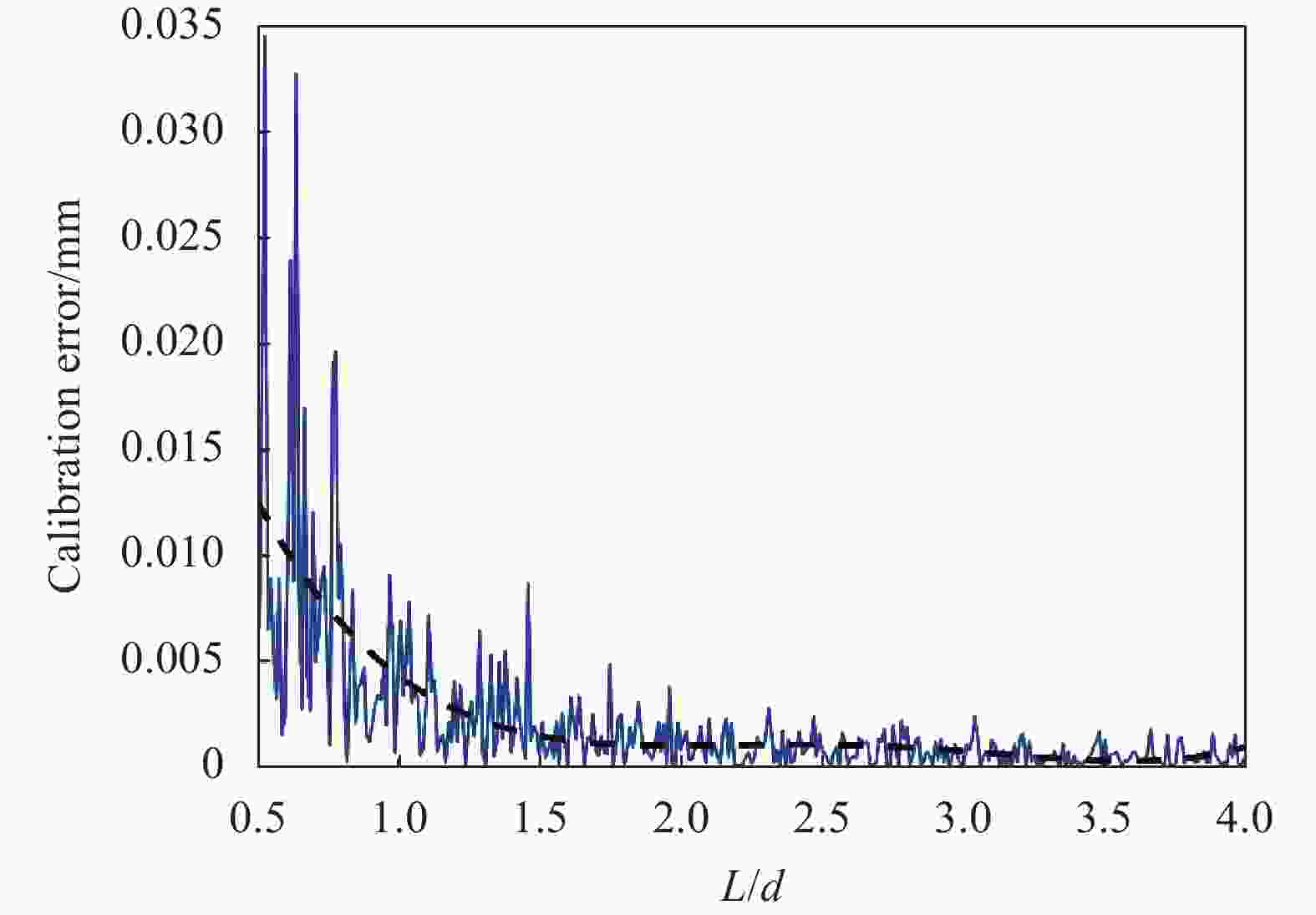
      Figure 3.  Calibration error in different values of L/d

      2)约束点数量N对标定精度的影响

      为了分析约束点数量N对基点标定精度的影响,根据1)中的仿真结果,确定约束直线长度L=3400 mm,激光跟踪干涉系统与约束直线的距离d=1700 mm,且位于约束直线的垂直平分线上。其余参数同表1,在约束直线上均匀等间选取约束点,约束点的数量N从10~80个点变化,分别计算标定误差与约束点个数的皮尔逊相关系数r,以此衡量约束点个数与标定误差的相关性。一般情况下,皮尔逊系数|r| < 0.3则认为他们没有相关性,仿真得到的皮尔逊相关系数r=0.045,所以当约束点大于10个之后,理论上约束点个数并不影响标定结果。为了保证结果的准确性与稳定性,采用了20个约束点进行实验和仿真。

      3)激光跟踪干涉系统的位置P0对标定精度的影响

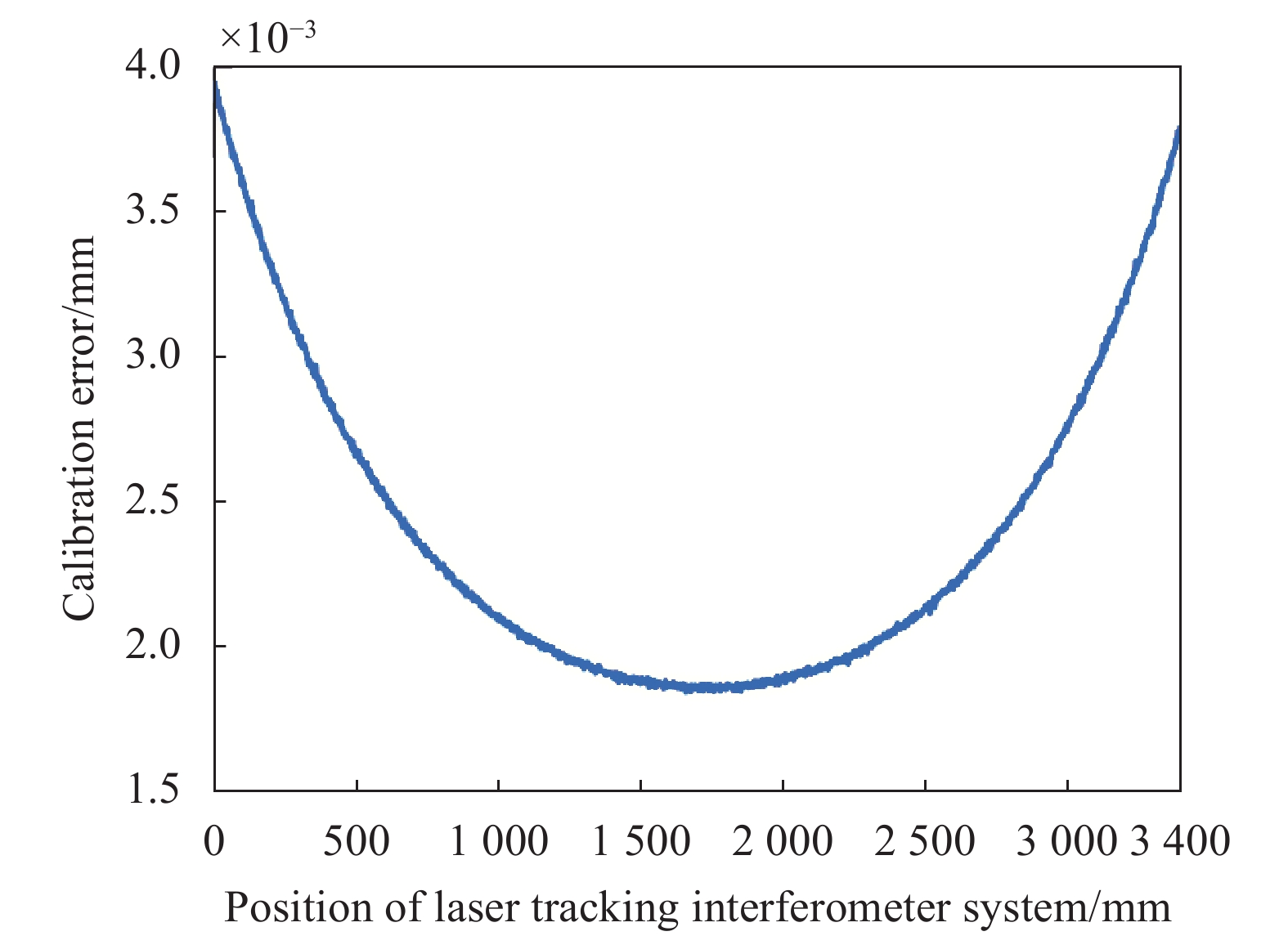
      为了研究激光跟踪干涉系统在x轴方向上的位置对标定精度的影响,选取约束点数量N=20个,约束直线长度L = 3400 mm,激光跟踪干涉系统与约束直线的距离d=1700 mm,激光跟踪干涉系统的x坐标沿约束直线方向变化,仿真结果如图4所示,当激光跟踪干涉系统位置的x坐标在1700 mm附近时,标定误差有最小值,即约束点要相对于激光跟踪干涉系统对称分布。

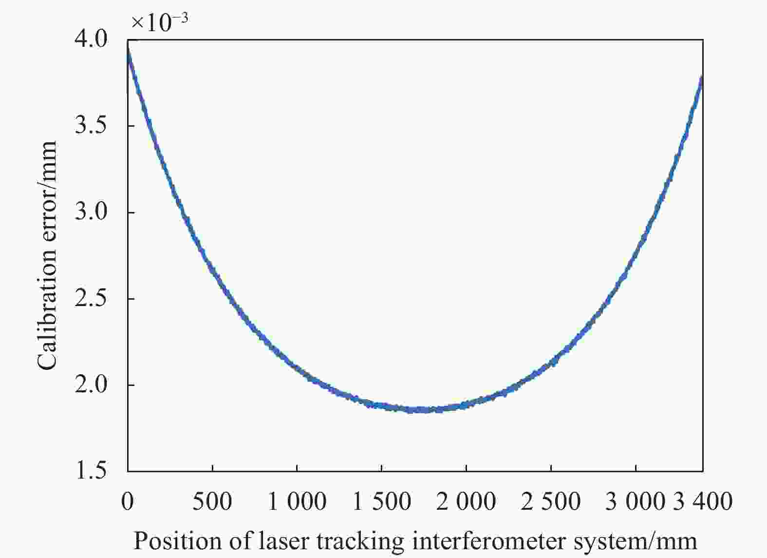
      Figure 4.  Influence of LTIS position on calibration error

      根据优化分析结果,结合实际实验条件,文中使用如下参数进行基点标定:约束直线长度为3400 mm,激光跟踪干涉系统与约束直线的垂直距离为1700 mm;约束点数量为20个,激光跟踪干涉系统放置在约束直线的垂直平分线附近,使约束点关于激光跟踪干涉系统大致对称分布。

    • 搭建实验系统对激光跟踪干涉系统的基点距离进行标定,如图5所示。雷尼绍XL80干涉仪7固定在气浮导轨4一端,调节角锥棱镜6与雷尼绍XL80干涉仪下的4维平台使XL80干涉仪准直。激光跟踪干涉系统2放置在气度导轨的垂直平分线附近,激光跟踪干涉系统与气浮导轨的距离为1700 mm。控制气浮导轨、激光跟踪干涉系统和雷尼绍XL80干涉仪示数归零。然后将目标靶镜5利用磁吸底座固定在基点靶座3上,使能激光跟踪干涉系统跟踪目标靶镜,将靶镜移动到气浮导轨上开始测量。

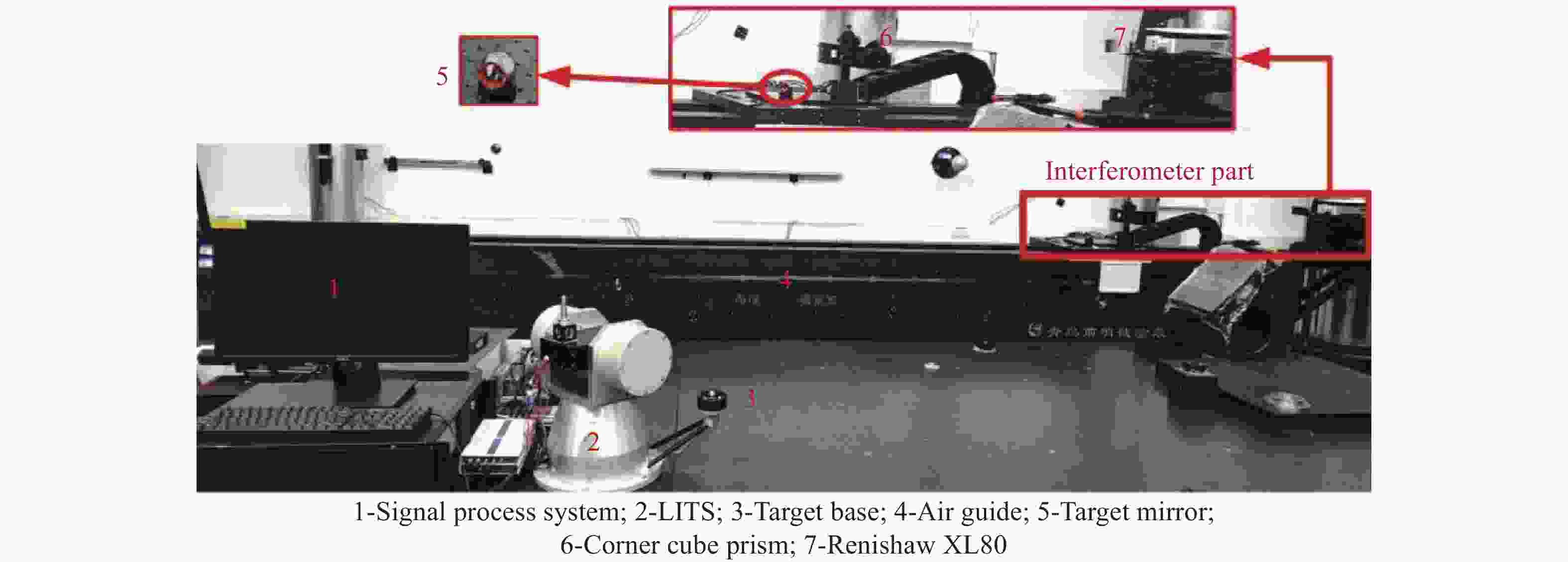
      Figure 5.  Experimental system of DBP calibration

      约束直线长度L=3400 mm,约束点个数N=20,激光跟踪干涉系统与约束直线的垂直距离d=1700 mm,激光跟踪干涉系统的位置在约束直线的垂直平分线附近,重复测量5次。实验结果如表2所示,激光跟踪干涉系统的基点距离平均值为290.0764 mm。

      No.DBP/mmAverage x0/mmAverage l0/mm
      1290.06881492.0213290.0764
      2290.0857
      3290.0748
      4290.0652
      5290.0877

      Table 2.  DBP calibration result for LTIS

      由于测量误差传播,最小二乘估计量的标准差取决于测量数据的标准差,由于每次测量的误差不同,这5次测量得到的最小二乘估计量的标准差也不同。根据最小二乘法的精度估计理论,可以求出每次测量中最小二乘估计量l0的标准差$ \sigma_{b_{0}} $。5次测量为不等精度测量,根据算数平均值原理,可以确定每组数据的权重$ p_{i} $,求出加权平均值$\overline l_0 $和加权平均值的标准差$ \sigma_{{\overline l_0}} $,经过计算,每次测量的标准差、权重、加权平均值和加权平均值的标准差如表3所示,激光跟踪干涉系统基点距离的平均值为29.0764 mm,算数平均值的标准差为4.4 μm。

      12345
      $ \sigma_{\|} $0.05020.11280.05110.05590.0473
      $ p_{i} $397.578.666382.44319.62446.27
      $ \bar{l}_{0} $29.0764 mm
      $ \sigma_{T_{1}} $4.4 μm

      Table 3.  Weight average and its standard deviation of DBP

    • 为了验证激光跟踪干涉系统基点距离标定结果的准确性,使用文中标定方法对API radian跟踪仪的基点距离进行标定,并与其标称值进行比较。约束直线长度L=3400 mm约束点数量N=20,API radian跟踪仪放置在约束直线的垂直平分线附近,API radian跟踪仪与约束直线的垂直距离d=1700 mm。实验系统如图6所示。对基点距离进行5次标定,取其加权平均值并计算加权平均值的标准差。API基点距离的标称值为154.1910 mm,标定结果如表4所示。对API跟踪仪的基点距离标定的结果为154.1940 mm,与其标称值相差3 μm。API 的全程3D空间精度为 10 μm+5 μm/m,实验结果表明,激光跟踪干涉系统基点的直线约束标定方法可以准确地对基点距离进行标定。

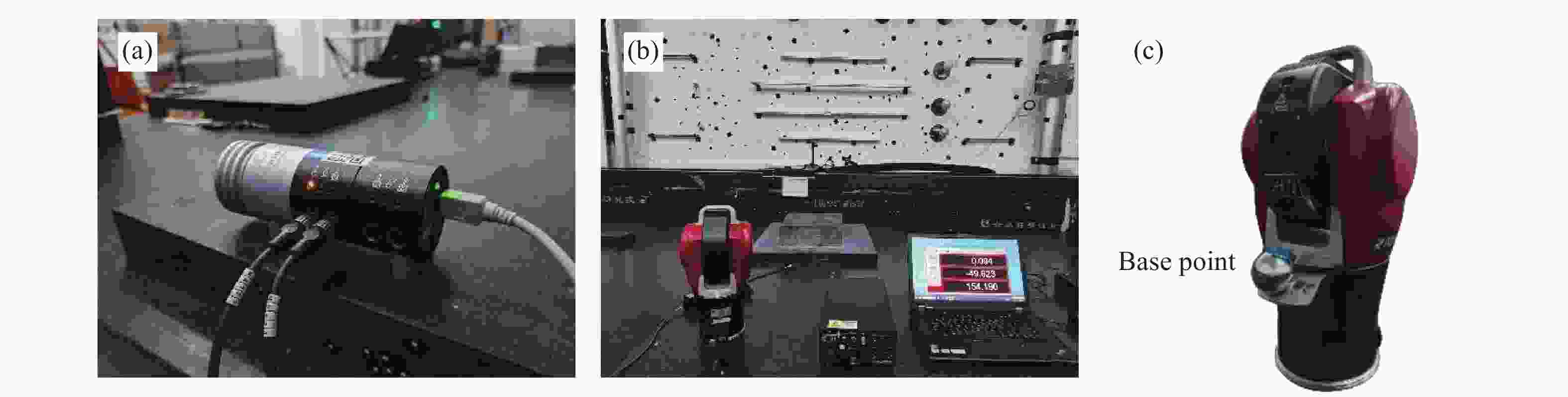
      Figure 6.  (a) Air refractive index compensation; (b) The verification experimental system of calibration; (c) API tracker

      No. DBP/mmWeighted average
      /mm
      API value/mmError
      /mm
      1154.2002154.1940154.19100.003
      2154.1892
      3154.1993
      4154.1868
      5154.1968

      Table 4.  DBP calibration results for API radian

    • 文中提出了一种激光跟踪干涉系统基点的直线约束标定方法,该方法在标定中仅使用了激光干涉仪与导轨,具有原理简单、精度高、误差源少的特点;分析了标定方法中各参数对基点距离标定精度的影响,确定了合适的约束直线长度L、激光跟踪干涉系统与约束直线的距离d、约束点个数N、激光跟踪干涉系统的位置P0,减小标定误差。

      利用激光跟踪干涉系统基点的直线约束标定方法对激光跟踪干涉系统的基点进行标定,该方法标定的激光跟踪干涉系统的基点距离的平均值为$\overline l_0 $=290.0764 mm,标准差为4.4 μm,对API radian跟踪仪的基点距离进行标定来验证标定结果的准确性,与标称值相比误差为3 μm。因此,文中激光跟踪干涉系统基点的直线约束标定方法标定出的基点距离精度满足工业机器人的标定需求,对工业机器人发展具有重要的意义。

Reference (17)

Catalog

    /

    DownLoad:  Full-Size Img  PowerPoint
    Return
    Return