Volume 52 Issue 8
Aug.  2023
Turn off MathJax
Article Contents

Wang Shiqiang, Meng Zhaozong, Gao Nan, Zhang Zonghua. Advancements in fusion calibration technology of lidar and camera[J]. Infrared and Laser Engineering, 2023, 52(8): 20230427. doi: 10.3788/IRLA20230427
Citation: Wang Shiqiang, Meng Zhaozong, Gao Nan, Zhang Zonghua. Advancements in fusion calibration technology of lidar and camera[J]. Infrared and Laser Engineering, 2023, 52(8): 20230427. doi: 10.3788/IRLA20230427

Advancements in fusion calibration technology of lidar and camera

doi: 10.3788/IRLA20230427
Funds:  National Natural Science Foundation of China (52275485)
  • Received Date: 2023-06-15
  • Rev Recd Date: 2023-07-10
  • Publish Date: 2023-08-28
  •   Significance   The data gathered by a singular sensor is inherently incomplete. For instance, the point clouds obtained by lidar lacks texture and color information, and the picture captured by camera lacks depth information. The data fusion of lidar and camera enable the harnessing of complementary information between the sensors, resulting in the acquisition of precise three dimensional (3D) spatial perception, which is widely applied in various fields, including autonomous driving and mobile robotics. In recent years, a lot of scholars at home and abroad have made significant research advancements in the field of sensor fusion, especially in the fusion of lidar and camera. However, there is a lack of a comprehensive paper summarizing the research achievement in the field of sensor fusion by scholars from various backgrounds. This paper provides a comprehensive summary of the research outcomes pertaining to the calibration method for lidar and camera fusion, which serves as a valuable reference for future researchers working in this field. Additionally, this paper serves as a helpful resource for beginners seeking a concise introduction to the subject, allowing them to quickly familiarize themselves with the calibration method for lidar and camera fusion.   Progress  First, the fundamental principles and techniques involved in the calibration of lidar and camera systems are presented. The fundamental principles of camera calibration is introduced. Moreover, a succinct overview of the existing camera calibration methods is provided, accompanied by a delineation of their individual characteristics. Simultaneously, the principle and classification of lidar are introduced, and the characteristics of different types of lidar are analyzed. A mathematical model for mechanical lidar is established and the calibration methods for internal parameters of mechanical lidar are summarized. Furthermore, the principle of joint calibration for lidar and camera is introduced.   Secondly, the calibration process of lidar and camera systems involves two main stages of feature extraction and feature matching. The processing methods of point cloud and image are briefly introduced, then extrinsic calibration methods of lidar and camera are emphatically introduced. The extrinsic calibration methods of lidar and camera systems can be categorized into target-based calibration, targetless-based calibration, motion-based calibration and deep learning-based calibration. The existing research results of each calibration method are summarized. The target-based calibration approach achieves high precision. However, it entails a complex calibration process. The targetless-based calibration method is simple and convenient, allowing for online calibration, but it exhibits lower calibration accuracy compared to the target-based calibration. The motion-based and deep learning-based calibration methods are considered as pivotal research directions for future advancements.   Finally, We conclude the paper and highlight the future development trends. Feature extraction and matching are the key progress in the calibration of lidar and camera. Although there have been many kinds of calibration methods for lidar and camera, it still needs a better way to improve the accuracy and robustness of the calibration results. In recent years, the development of deep learning technology has provided new opportunities for the fusion of lidar and camera data, and proposed new directions for online calibration in natural scene.   Conclusions and Prospects  Lidar and camera calibration has emerged as a significant research area, aiming to compensate for the limitations of individual sensor information and enable accurate perception of 3D information. The calibration technology primarily encompasses point cloud processing, image processing, and calibration methods. The crux of the calibration process lies in identifying corresponding features and subsequently matching them. In this paper, the characteristics of four distinct methods of targeted-based calibration, targetless-based calibration, motion-based calibration, and deep learning-based calibration are summarized. The accurate online calibration in diverse scenarios emerges as a prominent research focus in the future. In conclusion, the future research direction of calibration focuses on enhancing accuracy, improving robustness, online calibration, automating calibration, and establishing a unified verification standard. These advancements aim to further enhance the calibration process and its applicability in various domains.
  • [1] Xu X Q. Survey of multi-sensor data fusion target recognition algorithms [J]. Infrared and Laser Engineering, 2006, 35(S4): 321-328. (in Chinese)
    [2] Liu Y P, Guo X J, Su S J, et al. Review of a 3D lidar combined with single vision calibration[C]//IEEE International Conference on Data Science and Computer Application (ICDSCA), 2021, 2021: 397-404.
    [3] Kassir A, Peynot T. Reliable automatic camera-laser calibration[C]//Australian Robotics and Automation Association (ARAA), 2010: 1-10.
    [4] Mishra R K, Zhang Y. A review of optical imagery and airborne LiDAR data registration methods [J]. The Open Remote Sensing Journal, 2012, 5(1): 54-63. doi:  10.2174/1875413901205010054
    [5] Stamos I. Automated registration of 3D-range with 2D-color images: an overview[C]//44th Annual Conference on Information Sciences and Systems (CISS), 2010: 1-6.
    [6] Cui Y D, Chen R, Chu W B, et al. Deep learning for image and point cloud fusion in autonomous driving: a review [J]. IEEE Transactions on Intelligent Transportation Systems, 2022, 23(2): 722-739. doi:  10.1109/TITS.2020.3023541
    [7] Qiu Z Y, Martínez-sánchez J, Arias-sánchez P, et al. External multi-modal imaging sensor calibration for sensor fusion: A review [J]. Information Fusion, 2023, 97: 101806. doi:  10.1016/j.inffus.2023.101806
    [8] Zhang J, Jiang W T. Registration between laser scanning point cloud and optical images: status and trends [J]. Journal of Geo-information Science, 2017, 19(4): 528-539.
    [9] Kannala J, Brandt S S. A generic camera model and calibration method for conventional, wide-angle, and fish-eye lenses [J]. IEEE Transactions on Pattern Analysis and Machine Intelligence, 2006, 28(8): 1335-1340. doi:  10.1109/TPAMI.2006.153
    [10] Mei C, Rives P. Single view point omnidirectional camera calibration from planar grids[C]//IEEE International Conference on Robotics and Automation (ICRA), 2007: 3945-3950.
    [11] Yang X R, Zhang X W, Cheng S Y, et al. Progress on camera calibration methods in visual measurement [J]. Machinery Design and Manufacture, 2009, 217(3): 259-261.
    [12] Abdel-aziz Y I, Karara H M. Direct linear transformation from comparator coordinates into object space coordinates in close-range photogrammetry [J]. Photogrammetric Engineering and Remote Sensing, 2015, 5: 103-107.
    [13] Tsai R Y. An efficient and accurate camera calibration technique for 3D machine vision[C]//IEEE Conference of Computer Vision and Pattern Recognition(ICCV), 1986: 364-374.
    [14] Zhang Z Y. A flexible new technique for camera calibration [J]. IEEE Transactions on Pattern Analysis and Machine Intelligence, 2000, 22: 1330-1334. doi:  10.1109/34.888718
    [15] Faugeras O D, Luong Q T, Maybank S J. Camera self-calibration: theory and experiments[C]//European Conference on Computer Vision(ECCV), 1992: 321-334.
    [16] Beardsley P, Murray D. Camera calibration using vanishing points[C]//Proceedings of the British Machine Vision Conference (BMVC), 1992: 416-425.
    [17] Luong Q T, Faugeras O D. Self calibration of a moving camera from point correspondences and fundamental matrices [J]. International Journal of Computer Vision, 1997, 22(3): 261-289. doi:  10.1023/A:1007982716991
    [18] Ma S D. A self-calibration technique for active vision systems [J]. IEEE Transactions on Robotics and Automation, 1996, 12(1): 114-120. doi:  10.1109/70.481755
    [19] Zhang X L, Jiang K, Sun K, et al. Intrinsic parameters modeling for LiDAR and point cloud correction method [J]. Automotive Engineering, 2021, 43(8): 1228-1237, 1253.
    [20] Qiao D Y, Yuan W Z, Ren Y. Review of MEMS LiDAR [J]. Microelectronics and Computer, 2023, 40(1): 41-49.
    [21] Glennie C, Lichti D. Static calibration and analysis of the velodyne HDL-64 E S2 for high accuracy mobile scanning [J]. Remote Sensing, 2010, 2(6): 1610-1624. doi:  10.3390/rs2061610
    [22] Zhu Z, Liu J L. Calibration of a multi-beam LIDAR by using linear instrumental error model [J]. Applied Mechanics and Materials, 2013, 380: 911-914.
    [23] Muhammad N, Lacroix S. Calibration of a rotating multi-beam lidar[C]//IEEE/RSJ International Conference on Intelligent Robots and Systems(IROS), 2010: 5648-5653.
    [24] Bergelt R, Khan O, Hardt W. Improving the intrinsic calibration of a velodyne LiDAR sensor[C]//IEEE Sensors, 2017: 1-3.
    [25] Zalud L, Kocmanova P, Burian F, et al. Calibration and evaluation of parameters in a 3D proximity rotating scanner [J]. Elektronir Elektrotechnika, 2015, 21(1): 3-12.
    [26] Chan T O, Lichti D D. Automatic in situ calibration of a spinning beam LiDAR system in static and kinematic modes [J]. Remote Sensing, 2015, 7(8): 10480-10500. doi:  10.3390/rs70810480
    [27] Levinson J, Thrun S. Unsupervised calibration for multi-beam lasers [J]. Experimental Robotics, 2014, 1: 179-193.
    [28] Sun N, Qiu Q, Fan Z Q, et al. Intrinsic calibration of multi-beam LiDARs for agricultural robots [J]. Remote Sensing, 2022, 14(19): 4846. doi:  10.3390/rs14194846
    [29] Yang B S, Liang F X, Huang R G. Progress, challenges and perspectives of 3D lidar point cloud processing [J]. Acta Geodaetica et Cartographica Sinica, 2017, 46(10): 1509-1516.
    [30] Rusu R B, Marton Z C, Blodow N, et al. Towards 3D point cloud based object maps for household environments [J]. Robotics and Autonomous Systems, 2008, 56(11): 927-941. doi:  10.1016/j.robot.2008.08.005
    [31] Rusu R B, Cousins S. 3D is here: point cloud library (PCL)[C]//IEEE International Conference on Robotics and Automation (ICRA), 2011: 1-4.
    [32] Besl P J, Jain R C. Segmentation through variable-order surface fitting [J]. IEEE Transactions on Pattern Analysis and Machine Intelligence, 1988, 10(2): 167-192. doi:  10.1109/34.3881
    [33] Chen L, Cai Y, Zhang J S. Adaptive k-means clustering simplification of scattered point cloud [J]. Journal of Image and Graphics, 2017, 22(8): 1089-1097. (in Chinese)
    [34] Zhang Y H, Geng G H, Wei X R, et al. Feature extraction of point clouds using the DBSCAN clustering [J]. Journal of Xidian University, 2017, 44(2): 114-120. (in Chinese)
    [35] Sun Z L, Zhou Z R, Wu A Q. An improved mean shift algorithm used for point cloud dat a filtering [J]. Engineering of Surveying and Mapping, 2011, 20(5): 57-59. (in Chinese)
    [36] Wang Z Y, Zhang Y M, Chen Y B, et al. Optimization of indoor scene semantic segmentation network based on RGB-D image [J]. Automation and Information Engineering, 2020, 41(2): 27-32. (in Chinese)
    [37] Chernozhukov V, Chetverikov D, Demirer M, et al. Double/debiased machine learning for treatment and structural parameters [J]. The Econometrics Journal, 2017, 21(1): C1-C68.
    [38] Lyons E C. Digital image processing: an overview [J]. Computer, 1977, 10(8): 12-14. doi:  10.1109/C-M.1977.217813
    [39] Zhou H, Mao K Z. An impulsive noise color image filter using learning-based color morphological operations [J]. Digital Signal Processing, 2008, 18(3): 406-421. doi:  10.1016/j.dsp.2007.04.013
    [40] 龙建武. 图像阈值分割关键技术研究[D]. 长春: 吉林大学, 2014.
    [41] Yuan C L, Xiong Z L, Zhou X H, et al. Study of infrared image edge detection based on sobel operator [J]. Laser and Infrared, 2009, 39(1): 85-87. (in Chinese)
    [42] Li J S, Ma Y, Zhao F Z, et al. A novel arithmetic of image edge detection of canny operator [J]. Acta Photonica Sinica, 2011, 40(S1): 50-54.
    [43] Xiao M Y, Li X F, Zhang X L, et al. Medical image segmentation algorithm based on multi-scale region growing [J]. Journal of Jilin University, 2017, 47(5): 1591-1597. (in Chinese)
    [44] Wang G Q, Zhou X H, Yu L L. Image segmentation based on watershed algorithm [J]. Computer Simulation, 2009, 26(5): 255-258. (in Chinese)
    [45] Zhang Q L, Pless R. Extrinsic calibration of a camera and laser range finder (improves camera calibration)[C]\\IEEE/RSJ International Conference on Intelligent Robots and Systems(IROS), 2004: 2301-2306.
    [46] Unnikrishnan R, Hebert M. Fast extrinsic calibration of a laser rangefinder to a camera[D]. Pittsburgh: Carnegie Mellon University, 2005.
    [47] Geiger A Moosmann F, Car O, et al. Automatic camera and range sensor calibration using a single shot[C]//IEEE International Conference on Robotics and Automation (ICRA), 2012: 14-18.
    [48] Chen Y, Chen Z, Wei S G. Research on point cloud data segmentation based on extrinsic calibration of laser and CCD [J]. Microcomputer Information, 2008, 24(7): 295-297.
    [49] Han Z Y, Pu C G, Liu C. Extrinsic parameters calibration method for pinhole camera and 3D LiDAR [J]. Transducer and Microsystem Technologies, 2018, 37(4): 9-12, 16.
    [50] Wei K Q, Shi Z F, Li H, et al. Research on the joint calibration of monocular camera and 3D Lidar [J]. Navigation Positioning and Timing, 2015, 2(6): 69-74.
    [51] Li L, Zhang X, Tu D W. Joint calibration of 2D and 3D vision integrated sensor system [J]. Chinese Journal of Scientific Instrument, 2012, 33(11): 2473-2479. (in Chinese)
    [52] Xiang Z Y, Zheng L. Novel joint calibration method of camera and 3D laser range finder [J]. Journal of Zhejiang University(Engineering Science), 2009, 43(8): 1401-1405. (in Chinese)
    [53] Li H S, Luo X N, Deng C G, et al. Joint calibration of sports camera and lidar based on LM algorithm [J]. Journal of Guilin University of Electronic Technology, 2022, 42(5): 345-353.
    [54] Kang G H, Zhang Q, Zhang H, et al. Joint calibration of camera and lidar based on point cloud center [J]. Chinese Journal of Scientific Instrument, 2019, 40(12): 118-126. (in Chinese)
    [55] Zhou L. A new minimal solution for the extrinsic calibration of a 2d lidar and a camera using three plane-line correspondences [J]. IEEE Sensors Journal, 2014, 14(2): 442-454. doi:  10.1109/JSEN.2013.2284789
    [56] Dong F X, Cai J, Xie Y M. Joint calibration method for stereo vision system and 3D laser system [J]. Chinese Journal of Scientific Instrument, 2017, 38(10): 2589-2596. (in Chinese)
    [57] Yu D Q, Li G Y, Wang L, et al. Calibration of LiDAR and camera based on 3D feature point sets [J]. Bulletin of Surveying and Mapping, 2018, 11: 40-45.
    [58] Ha J E. Extrinsic calibration of a camera and laser range finder using a new calibration structure of a plane with a triangular hole [J]. International Journal of Control, Automation and Systems, 2012, 10: 1240-1244. doi:  10.1007/s12555-012-0619-7
    [59] Beltrán J, Guindel C, Escalera A, et al. Automatic extrinsic calibration method for LiDAR and camera sensor setups [J]. IEEE Transactions on Intelligent Transportation Systems, 2022, 23(10): 17677-17689. doi:  10.1109/TITS.2022.3155228
    [60] Debattisti S, Mazzei L, Panciroli M. Automated extrinsic laser and camera inter-calibration using triangular targets[C]//IEEE Intelligent Vehicles Symposium (IV), 2013: 696–701.
    [61] Huang Z Q, Su Y, Wang Q W, et al. Research on extrinsic parameter calibration method of 2D laser rangefinder (LRF) and visible light camera [J]. Chinese Journal of Scientific Instrument, 2020, 41(9): 121-129. (in Chinese)
    [62] Deng Z H, Liu M Y, Fu M Y. An improved method of matching point extracting for vision sensor and LMS space alignment [J]. Optical Technique, 2010, 36(1): 43-47.
    [63] Chen Z, Zhuo L, Sun K Q, et al. Extrinsic calibration of a camera and a laser range finder using point to line constraint [J]. Procedia Engineering, 2012, 29: 4348-4352. doi:  10.1016/j.proeng.2012.01.669
    [64] Dong W B, Isler V. A novel method for the extrinsic calibration of a 2D laser rangefinder and a camera [J]. IEEE Sensors Journal, 2018, 18(10): 4200-4211. doi:  10.1109/JSEN.2018.2819082
    [65] Pusztai Z, Hajder L. Accurate calibration of LiDAR-camera systems using ordinary boxes[C]//IEEE International Conference on Computer Vision Workshops (ICCV), 2017: 394-402.
    [66] Fan S, Yu Y, Xu M, et al. High-precision external parameter calibration method for camera and LiDAR based on a calibration device [J]. IEEE Access, 2023, 11: 18750-18760. doi:  10.1109/ACCESS.2023.3247195
    [67] Zhu F, Fan J, Huang Y C, et al. Extrinsic calibration of camera and 2D laser-rangefinder with various chessboard constrains [J]. Geomatics and Information Science of Wuhan University, 2019, 44(10): 1524-1529, 1537. (in Chinese)
    [68] Gong X J, Li Y, Liu J L. 3D Lidar-camera extrinsic calibration using an arbitrary trihedron [J]. Sensors, 2013, 13(2): 1902-1918. doi:  10.3390/s130201902
    [69] Toth T, Pusztai Z, Hajder L. Automatic LiDAR-camera calibration of extrinsic parameters using a spherical target[C]//IEEE International Conference on Robotics and Automation (ICRA), 2020: 8580-8586.
    [70] Liu C, Jiang Y, Yang M. Joint calibration of a camera and a laser range finder from grid calibration target[C]//IEEE International Conference on Cyber Technology in Automation, Control, and Intelligent Systems (CYBER), 2016: 497-501.
    [71] Moghadam P, Bosse M, Zlot R. Line-based extrinsic calibration of range and image sensors[C]\\IEEE International Conference on Robotics and Automation(ICRA), 2013: 6–10.
    [72] Scaramuzza D, Harati A, Siegwart R. Extrinsic self-calibration of a camera and a 3D laser range finder from natural scenes[C]//IEEE/RSJ International Conference on Intelligent Robots and Systems (IROS), 2007: 4164-4169.
    [73] Gomez-Ojeda R, Briales J, Fernandez-Moral E, et al. Extrinsic calibration of a 2D laser-rangefinder and a camera based on scene corners[C]//IEEE International Conference on Robotics and Automation (ICRA), 2015: 3611-3616.
    [74] Bai Z X, Jiang G, Xu A L. LiDAR-camera calibration using line correspondences [J]. Sensors, 2020, 20(21): 6319-6336. doi:  10.3390/s20216319
    [75] Kang J, Doh N L. Automatic targetless camera-LiDAR calibration by aligning edge with Gaussian mixture model [J]. Journal of Field Robotics, 2020, 37(1): 25-37.
    [76] Levinson J, Thrun S. Automatic online calibration of camerasand lasers[M/OL]. (2013-06-24)[2023-0-27]. https://rss2013.robotics.tu-berlin.de/images/booklet.online.pdf.
    [77] Yuan C J, Liu X Y, Hong X P, et al. Pixel-level extrinsic self calibration of high resolution LiDAR and camera in targetless environments [J]. IEEE Robotics and Automation Letters, 2021, 6(4): 7517-7524. doi:  10.1109/LRA.2021.3098923
    [78] Liu X Y, Yuan C J, Zhang F. Targetless Extrinsic Calibration of Multiple Small FoV LiDARs and Cameras Using Adaptive Voxelization [J]. IEEE Transactions on Instrumentation and Measurement, 2022, 71: 1-12.
    [79] Wang W M, Nobuhara S, Nakamura R, et al. SOIC: semantic online initialization and calibration for LiDAR and camera[EB/OL]. (2020-03-09)[2023-06-15]. https://arxiv.org/abs/2003.04260.
    [80] Abedini A. An investigation into the registration of LiDAR intensity data and aerial images using the SIFT approach[C]//The International Archives of The Photoghrammetry, Remote Sensing and Spatial Information Sciences(ISPRS), 2008: 169–176.
    [81] Pandey G, McBride J, Savarese S, et al. Automatic targetless extrinsic calibration of a 3D LiDAR and camera by maximizing mutual information[C]//AAAI Conference on Artificial Intelligence (AAAI), 2012, 26(1): 2053-2059.
    [82] Pandey G, Mcbride J R, Savarese S, et al. Automatic extrinsic calibration of vision and LiDAR by maximizing mutual information [J]. Journal of Field Robotics, 2015, 32(5): 696-722. doi:  10.1002/rob.21542
    [83] Taylor Z, Nieto J. A mutual information approach to automatic calibration of camera and lidar in natural environments[C]//Australian Conference on Robotics and Automation (ACRA), 2012: 3-9.
    [84] Song W S, Zhang Z H, Gao N, et al. Spatial pose calibration method for lidar and camera based on intensity information [J]. Laser & Optoelectronics Progress, 2022, 59(2): 356-364. (in Chinese)
    [85] Huang K H, Stachniss C. Extrinsic multi-sensor calibration for mobile robots using the Gauss-Helmert model[C]//IEEE, RSJ International Conference on Intelligent Robots and Systems (IROS), 2017: 1970-1976.
    [86] Taylor Z, Nieto J. Motion-based calibration of multi modal sensor arrays[C]\\IEEE International Conference on Robotics and Automation (ICRA), 2015: 4843-4850.
    [87] Ishikawa R, Oishi T, Ikeuchi K. LiDAR and camera calibration using motion estimated by sensor fusion odometry[C]//IEEE/RSJ International Conference on Intelligent Robots and Systems (IROS), 2018: 7342-7349.
    [88] Zhao W, Nister D, Hsu S. Alignment of continuous video onto 3D point clouds [J]. IEEE Transactions on Pattern Analysis and Machine Intelligence, 2005, 27(8): 1305-1318. doi:  10.1109/TPAMI.2005.152
    [89] Yang C, Li T J, Hu H, et al. Online lidar calibration algorithm based on nonlinear optimization [J]. Computer Engineering and Design, 2021, 42(7): 1919-1925.
    [90] Nedevschi S. Online cross-calibration of camera and lidar[C]//IEEE International Conference on Intelligent Computer Communication and Processing (ICCP), 2017: 295-301.
    [91] Schneider N, Piewak F, Stiller C, et al. RegNet: multimodal sensor registration using deep neural networks[C]//IEEE Intelligent Vehicles Symposium (IV), 2017: 1803-1810.
    [92] Iyer G, Ram R K, Murthy J K, et al. CalibNet: Geometrically supervised extrinsic calibration using 3D spatial transformer networks[C]//IEEE/RSJ International Conference on Intelligent Robots and Systems (IROS), 2018: 1110-1117.
    [93] Yuan K, Guo Z, Wang Z J. RGGNet: Tolerance aware LiDAR-camera online calibration with geometric deep learning and generative model [J]. IEEE Robotics and Automation Letters, 2020, 5(4): 6956-6963. doi:  10.1109/LRA.2020.3026958
    [94] Lv X D, Wang B, Dou Z, et al. LCCNet: LiDAR and camera self-calibration using cost volume network[C]//IEEE Conference on Computer Vision and Pattern Recognition Workshops (CVPR), 2021: 2888-2895.
    [95] Cattaneo D, Vaghi M, Ballardini A L, at el. CMRNet: Camera to LiDAR-map registration[C]//IEEE Intelligent Transportation Systems Conference(ITSC), 2019: 1283-1289.
    [96] Shi J Y, Zhu Z H, Zhang J H, et al. CalibRCNN: Calibrating camera and LiDAR by recurrent convolutional neural network and geometric constraints[C]//IEEE, RSJ International Conference on Intelligent Robots and Systems(IROS), 2020: 1283-1289.
    [97] Zhao G N, Hu J S, You S Y, et al. CalibDNN: multi-modal sensor calibration for perception using deep neural networks[C]//Conference on Signal Processing, Sensor/Information Fusion, and Target Recognition, 2021: 324-335.
    [98] Lv X D, Wang S, Ye D. CFNet: LiDAR-camera registration using calibration flow network [J]. Sensors, 2021, 21(23): 8112-8124. doi:  10.3390/s21238112
    [99] Jing X, Ding X Q, Xiong R, et al. DXQ-Net: Differentiable LiDAR-camera extrinsic calibration using quality-aware flow[C]//International Conference on Intelligent Robots and Systems(IROS), 2022: 6235-6241.
    [100] Yi W, Zhu M, Liang J. PSNet: LiDAR and camera registration using parallel Subnetworks [J]. IEEE Access, 2022, 10(1): 70553-70561.
    [101] Sun Y, Li J, Wang Y, et al. ATOP: An attention-to-optimization approach for automatic LiDAR-camera calibration via cross-modal object matching [J]. IEEE Transactions on Intelligent Vehicles, 2023, 8(1): 696-708. doi:  10.1109/TIV.2022.3184976
  • 加载中
通讯作者: 陈斌, bchen63@163.com
  • 1. 

    沈阳化工大学材料科学与工程学院 沈阳 110142

  1. 本站搜索
  2. 百度学术搜索
  3. 万方数据库搜索
  4. CNKI搜索

Figures(7)  / Tables(3)

Article Metrics

Article views(326) PDF downloads(141) Cited by()

Related
Proportional views

Advancements in fusion calibration technology of lidar and camera

doi: 10.3788/IRLA20230427
  • School of Mechanical Engineering, Hebei University of Technology, Tianjin 300130, China
Fund Project:  National Natural Science Foundation of China (52275485)

Abstract:   Significance   The data gathered by a singular sensor is inherently incomplete. For instance, the point clouds obtained by lidar lacks texture and color information, and the picture captured by camera lacks depth information. The data fusion of lidar and camera enable the harnessing of complementary information between the sensors, resulting in the acquisition of precise three dimensional (3D) spatial perception, which is widely applied in various fields, including autonomous driving and mobile robotics. In recent years, a lot of scholars at home and abroad have made significant research advancements in the field of sensor fusion, especially in the fusion of lidar and camera. However, there is a lack of a comprehensive paper summarizing the research achievement in the field of sensor fusion by scholars from various backgrounds. This paper provides a comprehensive summary of the research outcomes pertaining to the calibration method for lidar and camera fusion, which serves as a valuable reference for future researchers working in this field. Additionally, this paper serves as a helpful resource for beginners seeking a concise introduction to the subject, allowing them to quickly familiarize themselves with the calibration method for lidar and camera fusion.   Progress  First, the fundamental principles and techniques involved in the calibration of lidar and camera systems are presented. The fundamental principles of camera calibration is introduced. Moreover, a succinct overview of the existing camera calibration methods is provided, accompanied by a delineation of their individual characteristics. Simultaneously, the principle and classification of lidar are introduced, and the characteristics of different types of lidar are analyzed. A mathematical model for mechanical lidar is established and the calibration methods for internal parameters of mechanical lidar are summarized. Furthermore, the principle of joint calibration for lidar and camera is introduced.   Secondly, the calibration process of lidar and camera systems involves two main stages of feature extraction and feature matching. The processing methods of point cloud and image are briefly introduced, then extrinsic calibration methods of lidar and camera are emphatically introduced. The extrinsic calibration methods of lidar and camera systems can be categorized into target-based calibration, targetless-based calibration, motion-based calibration and deep learning-based calibration. The existing research results of each calibration method are summarized. The target-based calibration approach achieves high precision. However, it entails a complex calibration process. The targetless-based calibration method is simple and convenient, allowing for online calibration, but it exhibits lower calibration accuracy compared to the target-based calibration. The motion-based and deep learning-based calibration methods are considered as pivotal research directions for future advancements.   Finally, We conclude the paper and highlight the future development trends. Feature extraction and matching are the key progress in the calibration of lidar and camera. Although there have been many kinds of calibration methods for lidar and camera, it still needs a better way to improve the accuracy and robustness of the calibration results. In recent years, the development of deep learning technology has provided new opportunities for the fusion of lidar and camera data, and proposed new directions for online calibration in natural scene.   Conclusions and Prospects  Lidar and camera calibration has emerged as a significant research area, aiming to compensate for the limitations of individual sensor information and enable accurate perception of 3D information. The calibration technology primarily encompasses point cloud processing, image processing, and calibration methods. The crux of the calibration process lies in identifying corresponding features and subsequently matching them. In this paper, the characteristics of four distinct methods of targeted-based calibration, targetless-based calibration, motion-based calibration, and deep learning-based calibration are summarized. The accurate online calibration in diverse scenarios emerges as a prominent research focus in the future. In conclusion, the future research direction of calibration focuses on enhancing accuracy, improving robustness, online calibration, automating calibration, and establishing a unified verification standard. These advancements aim to further enhance the calibration process and its applicability in various domains.

    • 多模态传感器数据融合技术是指将信息互补的不同类型传感器数据融合,获得更全面、准确的综合数据而达到精确感知环境信息的目的[1]。近年来,智能化成为各行业趋势,单一传感器采集的数据不能准确描述环境数据信息。多模态传感器融合技术的发展弥补了单一传感器的缺点,实现不同传感器的数据互补,被广泛应用于遥感感知、机器人技术、自动驾驶、三维空间信息重建等领域。目前在信息感知融合领域常用的传感器有:毫米波雷达(Radar)、激光雷达(Lidar)、彩色相机(Camera)、红外传感器(Infrared Sensor)、惯性测量单元(Inertial Measurement Unit, IMU)等。不同传感器的应用领域各不相同,联合使用这些传感器可获得更丰富的数据信息。

      激光雷达通过发射光束测量目标到激光雷达接收器的距离,得到精确的三维点云数据,被应用于障碍检测、实时地图构建、自助导航等领域[2]。激光雷达采集的点云数据精度高、抗干扰性好,不受光照变化影响,有准确的深度信息,但缺乏色彩和纹理信息。相机作为最常见的传感器,通过拍照采集目标图像提供丰富的视觉信息,被广泛用于目标检测、场景理解等领域,但相机缺乏深度信息且稳定性差,易受光照、天气影响。激光雷达和相机数据融合可实现两传感器信息互补,得到更丰富的三维环境信息,被广泛用于遥感测量、自动驾驶、机器人技术等领域。

      多源数据信息融合的首要步骤是传感器间精确稳定的外部校准,找到合适的变换矩阵,实现激光雷达和相机两坐标系数据点间的相互转化[3]。传感器标定主要涉及内参标定和外参标定。内参主要描述传感器内部信息的映射关系,例如相机的焦距($ {{f}}_{x}{,{f}}_{y} $)、主点坐标($ {{{C}}_{{x}},{C}}_{y} $)、畸变参数($ {k}1,{k}2,{p}1,{p}2 $)及激光雷达的角度偏差($ \;{\beta } $)、距离偏差($ {s},{ }{ }{ }{ }{H},{ }{V},{ }{D} $),外参标定主要描述两个传感器间的位姿关系。

      激光雷达与相机标定的综述论文局限于某特定领域校准分析研究。Mishra等[4]综述研究遥感领域机载雷达和光学相机的校准方法,并指出自动化和高精度是未来该领域校准设计目标。Stamos I[5]综述了大场景下3D距离和2D图像自动标定方法。Cui等[6]综述了深度学习在图像和点云融合的应用,但领域局限于自动驾驶。Qiu等[7]综述了激光雷达、相机和毫米波雷达三个传感器的外参标定方法,但激光雷达和相机外参标定的内容并不全。张靖等[8]综述机载雷达和光学影像的配准方法,也仅局限于遥感检测领域。以纯理论视角分析激光雷达和相机外参标定方法的论文尚有缺失,针对此情况本论文整合现有激光雷达和相机联合标定方法,有助初学者快速入门本方向研究。

    • 将激光雷达点云数据和彩色相机像素数据统一到参考坐标系,实现两传感器校准过程主要涉及相机和激光雷达的内参标定、相机与激光雷达外参标定。本章节介绍激光雷达和相机的内参标定原理及方法,概述激光雷达与相机外参标定原理。

    • 相机将输入3D场景映射为一张RGB图片,标定就是找到相关数学模型近似逼近此复杂映射过程,即展示图像和实际物理世界的关系。标定后的相机用于各种计算机视觉任务,如深度恢复、三维重建等,本质上都是对丢失距离信息的恢复,具体流程见图1

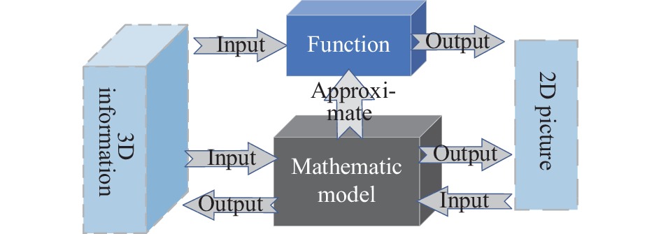
      Figure 1.  Camera model mapping process

      常见的相机模型有针孔模型、透视模型、鱼眼模型和全景模型等。透视模型可认为考虑镜头畸变针孔模型的拓展,常见工业相机都采用透视模型。鱼眼模型和全景模型分别对应的是鱼眼相机和全景相机,这两类相机具有视野好、畸变大的特点。Kannala等[9]提出用入射角的奇数次泰勒展开式标定鱼眼相机,Mei[10]提出单位球投影标定全景相机,此方法同样适用鱼眼相机。

      普通相机标定多用针孔模型,数学计算模型为:

      式中:s为尺度因子;($ {u},{v} $)为图像像素坐标;$ \boldsymbol{K} $为相机内参矩阵;$ \boldsymbol{R} $为相机外参旋转矩阵;$ \boldsymbol{t} $为相机外参平移矩阵;($ {{X}}_{w},{{Y}}_{w},{{Z}}_{w} $)为采集点世界坐标。标定方法分为传统标定、相机自标定、主动视觉标定三种[11]。传统标定法有直接线性标定法[12]、Tasi两步法[13]和张氏标定法[14]等;自标定法主要有Kruppa方程自标定[15]、消失点自标定[16]、光束法自标定[17]等;主动视觉标定法由Ma[18]提出,通过主动系统控制相机运动实现。

      从稳定性(Stability)、精确性(Accuracy)、灵活性(Flexibility)、标定速度(Speed)及是否需要标靶(Target)分析相机标定方法特点,如表1所示。Stability描述算法计算结果是否稳定,Accuracy描述计算结果精度,Flexibility描述算法对环境的依赖性,Speed描述算法计算速度,Target判断标定过程是(Y)、否(N)需要标靶。DLT表示直接线性标定法,Tasi表示Tasi两步法,Zhang表示张氏标定,Kruppa表示Kruppa方程法,VP表示消失点自标定,BA表示光束法自标定,AVC主动视图标定法。L表示低,M表示中,H表示高。

      Calibration methodStabilityAccuracyFlexibilitySpeedTarget
      Traditional methodsDLT[12]LLLHY
      Tasi[13]MHLMY
      Zhang[14]MHMMY
      Self-calibration methodsKruppa[15]MMHHN
      VP[16]LMHHN
      BA[17]LMHMN
      AVC[18]HHLLY

      Table 1.  Characteristics of different camera intrinsic calibration methods

    • 激光雷达是激光探测与测距系统简称。通过测定传感器发射器与目标物体之间距离,分析目标物体表面反射能量大小、反射波谱的幅度、频率和相位等信息,呈现目标精确三维结构信息[19]。激光雷达的测距原理为时间飞行法,通过测量激光脉冲在雷达和目标之间的飞行时间获取激光雷达到目标的距离信息,如公式(2)所示:

      式中:$ {c} $为光空气传播速度;$ \Delta {t} $为发出到接收光波脉冲时间差。

      根据激光扫描方式激光雷达可分为:机械式激光雷达(Mechanical Lidar)和固态激光雷达(Solid-State Lidar)。机械旋转激光雷达分为单线扫描激光雷达和多线扫描激光雷达;固态激光雷达又分为MEMS (Micro Electromechanical System)激光雷达、光学相控阵(Optical Phased Array, OPA)激光雷达和泛光面阵式激光雷达(Flash)。机械旋转激光雷达主要通过旋转扫描激光发射器获取周围的环境信息;MEMS激光雷达内部采用MEMS微震镜实现多密度环境感知,为半固态激光雷达(Semi-solid State Lidar);OPA和Flash激光雷达可通过一定技术实现直接获取空间三维信息,为全固态激光雷达(All-solid State Lidar)。表2为不同类型激光雷达特点[20],机械式激光雷达视野好,可实现大范围场景信息测量,技术方案成熟,为当前使用最多的激光雷达。文中以此类型雷达展示测量原理和标定方案。

      No.TypeTechnologyAdvantageDisadvantage
      1Mechanical lidarSingle line scanning or multi-line scanningCircular scanning, large scanning field,
      mature technology
      Large volume, short life and high cost
      2Semi-solid state lidarMEMS methodSize miniaturization, low cost and high accuracySensitive to vibration, small field of vision
      3All-solid
      state lidar
      OPA methodSilicon-based scheme, low costThe technology is not mature and the application is few
      4Flash methodSmall size, 360° field of viewLow efficiency, immature technology

      Table 2.  Characteristics of different type lidar

      图2为多线机械式激光雷达扫描原理图。激光雷达采集初始数据为($ {{R}}_{{i}},{{\delta }}_{{i}},{\varepsilon } $),其中$ {{R}}_{{i}} $为光束$ {i} $的扫描距离;$ {{\delta }}_{{i}} $为光束$ {i} $俯仰扫描角;$ {\varepsilon } $为光束$ {i} $水平扫描角。内参是($ {{s}}^{{i}},{{\beta }}_{{i}},{{H}}_{{o}}^{{i}},{{V}}_{{o}}^{{i}}{,{D}}_{{o}}^{{i}} $),$ {{s}}^{{i}} $为光束i扫描距离的尺度因子,$ {{\;\beta }}_{{i}} $表示光束$ {i} $水平扫描角的偏差,$ {{H}}_{{o}}^{{i}} $表示光束$ {i} $原点的水平偏移,$ {{V}}_{{o}}^{{i}} $表示光束$ {i} $原点的垂直偏移,$ {{D}}_{{o}}^{{i}} $为光束$ {i} $原点与旋转轴的偏移。设点云三维坐标为($ {{x}}_{{i}},{{y}}_{{i}},{{z}}_{{i}} $),多线激光雷达数学模型构建为:

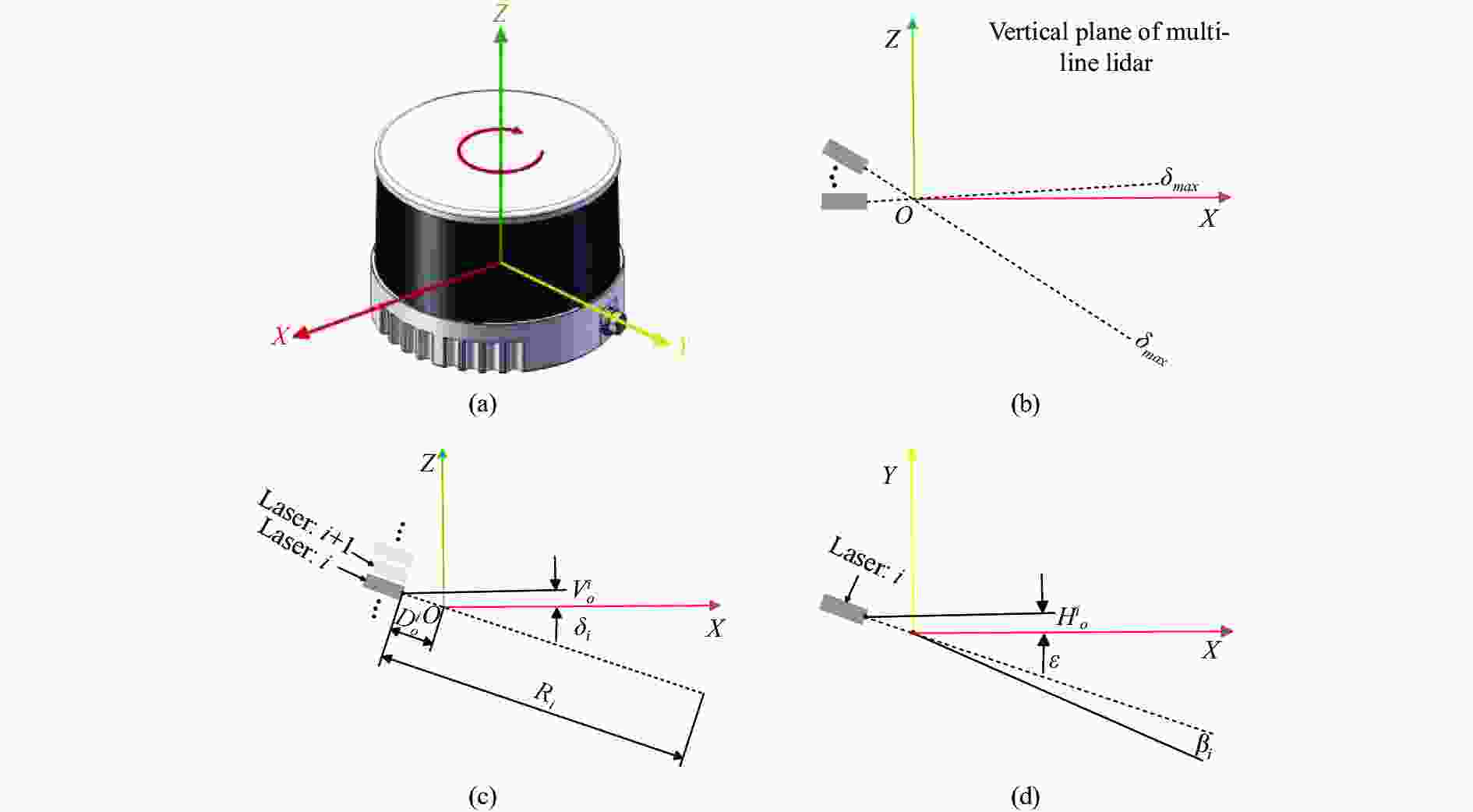
      Figure 2.  (a) Coordinate system of lidar; (b) Scanning range in the vertical direction (${\delta }_{\min}-{\delta }_{\max}$); (c); Scanning parameters in the vertical plane; (d) Scanning parameters on the horizontal plane

      公式(3)是多线激光雷达通用数学模型,国内外学者根据此内参模型标定激光雷达内参。Glennie等[21]提出了一种基于平面特征最小二乘平差法,并将其应用于最小约束网络中,计算激光器内部标定参数最优解,标定需要在静态环境下完成。Zhu等[22]和Muhammad等[23]对比激光雷达检测值和标准平面真实值,优化激光雷达内参,区别在于前者没有考虑尺度因子$ {{s}}^{{i}} $。Bergelt等[24]提出点云到拟合平面距离偏差最小准则标定激光雷达内参,但没有用实验证实该方法。Zalud等[25]提出一种基于条件调整方程测量校准方法,并将校准结果与原厂进行比较,证明了该方法的有效性。Chan等[26]基于柱表面特征(如灯杆)的约束点云和拟合三维柱表面模型计算32线激光雷达的固有参数。Levinson 等[27]提出了一种无监督校准方法,定义能量函数标定激光雷达的内外参数。Sun等[28]通过对激光雷达点云拟合平面的非线性优化,完成64线束激光雷达内参标定。不考虑外部震动等干扰因素影响,传感器装配完成之后,内参值会被厂商给定,并保持不变,常见的标定为外参标定,即激光雷达和彩色相机的位姿关系。

    • 融合激光雷达点云和相机图像数据需要对激光雷达和摄像机的相对位姿标定,其原理如图3所示。激光雷达和相机组成的标定系统包含4种坐标系,即激光雷达坐标系($ {{O}}_{{l}}-{{X}}_{{l}}{{Y}}_{{l}}{{Z}}_{{l}} $)、相机坐标系($ {{O}}_{{c}}-{{X}}_{{c}}{{Y}}_{{c}}{{Z}}_{{c}} $)、像素坐标系($ {O}-{U}{V} $)和世界坐标系($ {{O}}_{{w}}-{{X}}_{{w}}{{Y}}_{{w}}{{Z}}_{{w}} $)。激光雷达坐标系坐标点与相机坐标系坐标点的转化参数就是激光雷达和相机的外参,它们的外参计算需要找到彼此的共有特征,即同名特征,常见的特征有点、线、面特征和互信息等。

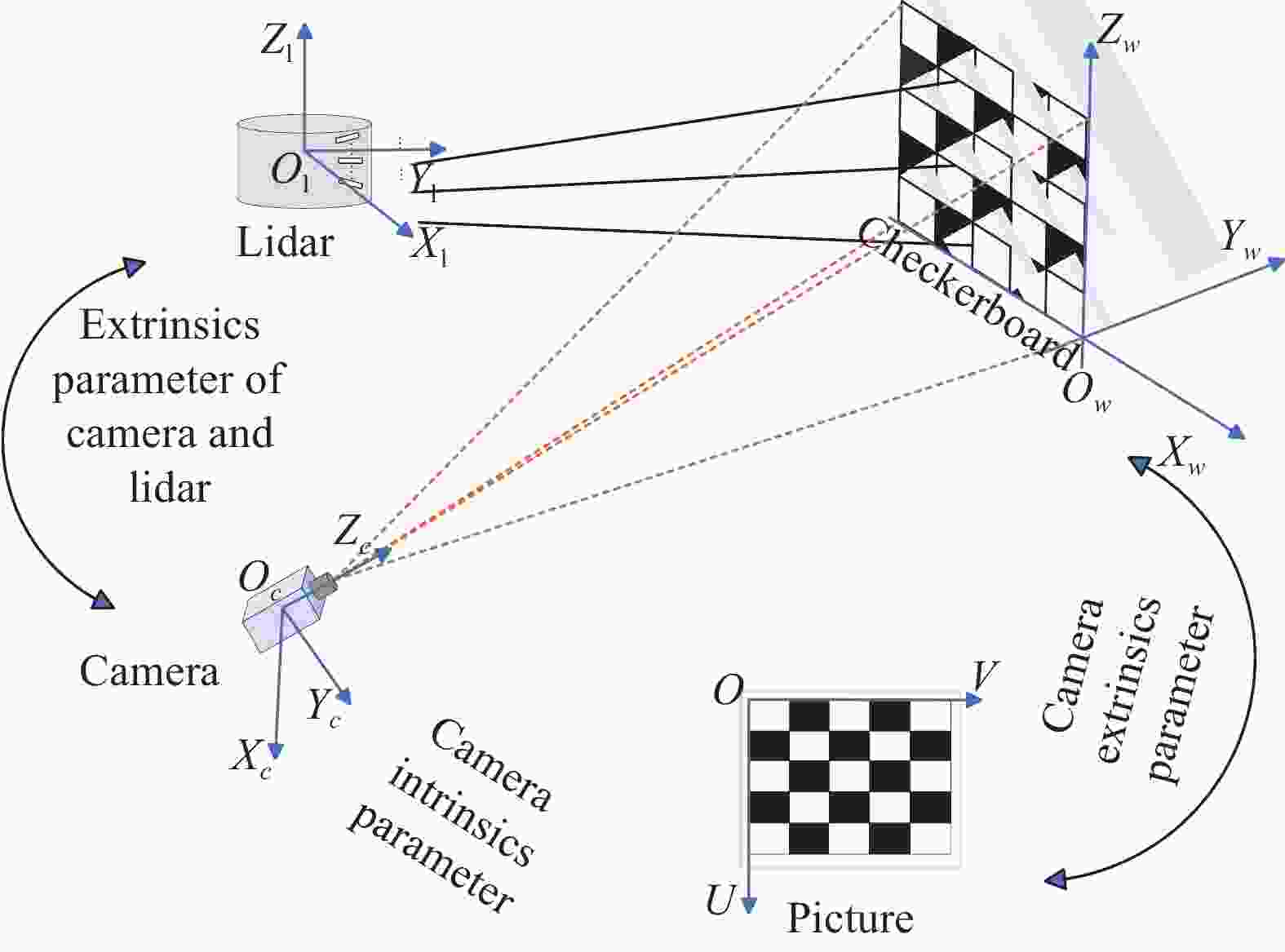
      Figure 3.  Calibration principle of lidar and camera

      设($ {u},{v} $)为相机采集的像素坐标,($ {{x}}_{l},{{y}}_{l},{{z}}_{l} $)激光雷达的点云坐标,相机内参为$ \boldsymbol{K} $,此为已知数据。$ {\boldsymbol{R}}_{\mathit{l}}^{\mathit{c}}{、}{\boldsymbol{t}}_{\mathit{l}}^{\mathit{c}} $为激光雷达到相机的旋转和平移矩阵,此为未知数据。激光雷达与相机外参标定原理为:

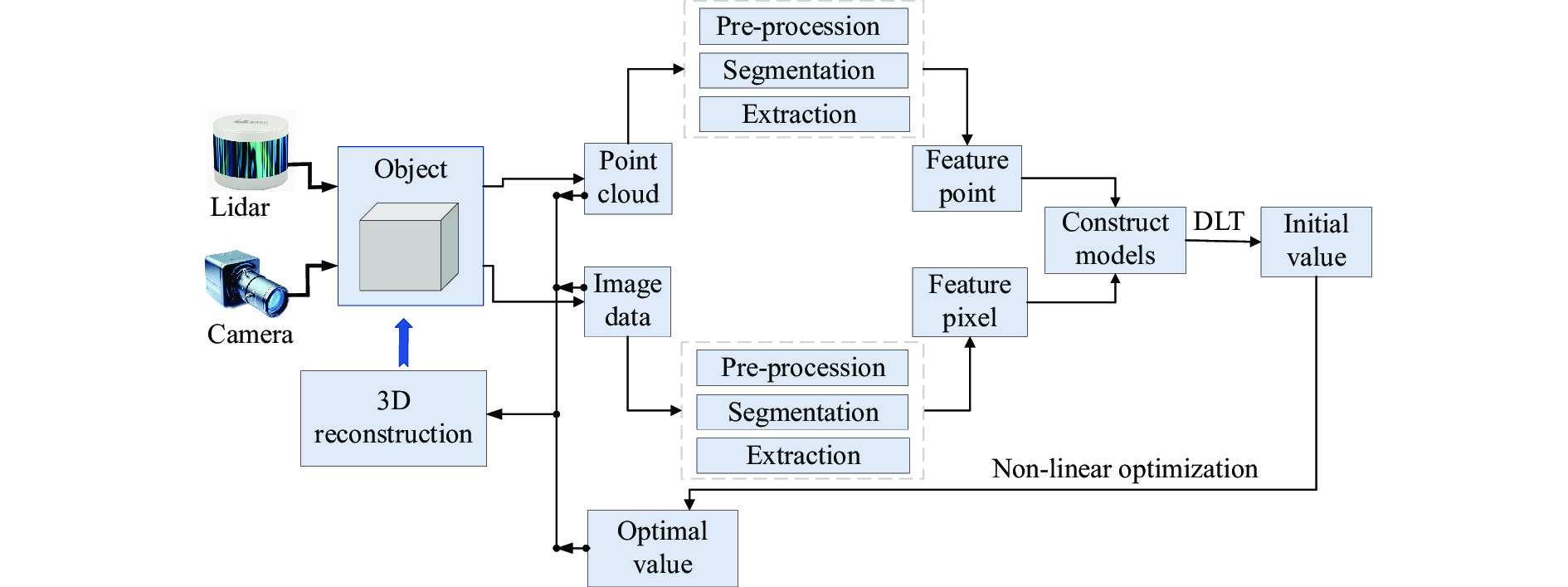
    • 激光雷达和相机融合实现三维重建过程中采集的初始数据是单传感器模型下各自的数据类型,即点云数据和图像数据。为实现两传感器的特征匹配,需要分别对单传感器模型采集的数据处理,然后完成激光雷达和相机位姿匹配。激光雷达和相机外参标定的主要内容包括:点云处理、图像处理、激光雷达和相机外参标定,如图4所示。

      Figure 4.  Multi-source data fusion process

    • 实际工程案例中,激光雷达采集的点云会由于设备、环境等因素影响分布杂乱并呈现噪声。为准确获取与图像对应的同名数据,需要对点云处理。点云处理方法包括:预处理、分割、特征提取等[29]。预处理包括滤波、精简、分割等,目的是排除干扰、平滑点云、精简点云。为得到最佳效果,预处理的顺序可以调整或反复叠加。滤波具有排除干扰和提取特征的功能,常见滤波方法有:高斯滤波、直通滤波、条件滤波等[30-31]

      点云分割获取与图像重合的特征区域,常见的分割方法有:点云几何属性(如点距离、法线方向和曲率等[32])、聚类分割(K均值聚类[33]、密度聚类[34]和均值漂移聚类[35]等)、颜色特征(RGB值和颜色直方图[36])、深度学习(卷积神经网络、图卷积神经网络等模型[37])、形状特征(向量场直方图)。

      特征提取是对分割后区域提取与图像对应的同名特征。点云特征提取可分两种形式进行:第一种是直接特征提取,利用体素网格、关键点检测、法线和点云估计等方法提取特征;第二种是间接特征提取,将点云数据转换成深度图和距离图,利用图像处理的方法提取特征。

    • 相机采集的图片也需要处理得到与点云对应的同名特征,处理方法有:滤波、分割、特征提取等[38]。滤波具有去除图像噪音,增强特征细节作用,常见图像滤波有均值滤波、中值滤波和高斯滤波等[39]。图像分割是寻找和点云对应的同名特征所在区域,常见分割方法有:阈值分割[40]、边缘检测(Sobel算子[41],Canny算子[42])、区域生长[43]、分水岭算法[44]等。图像特征包括边缘特征、角点检测和纹理特征等,提取特征时需要图像灰度转换和图片增强等处理。

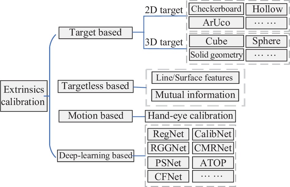
    • 激光雷达和相机位姿配准是三维离散点和二维连续点的复杂性匹配问题,是当前自动驾驶、移动机器人技术、三维空间重建等领域研究的重点。为准确分析激光雷达和相机外参标定研究成果,本章节从基于标靶标定、基于无标靶标定、基于运动标定和基于深度学习标定四方面对现有研究成果归纳总结,如图5所示。

      Figure 5.  The extrinsic calibration methods of lidar and camera

    • 基于标靶标定是指手动或自动在自然环境中寻找标靶,提取标靶特征建立模型完成激光雷达和相机外参标定。有标靶标定外参选用的同名特征有点特征、线特征、面特征或者混合特征。点特征有2D-3D点和3D-3D点。常用标靶有三角板、ArUco标定板、球体、立方体等,基于标靶标定可细分为:棋盘格二维标靶、非棋盘格二维标靶、其他三维标靶。

      1) 棋盘格二维标靶标定

      图6所示为棋盘格的两种形式:有边框和无边框。棋盘格标靶角点明显,标定精度高,容易制作,是最常用的激光雷达和相机外参标定标靶。华盛顿大学Zhang等[45]利用点在面上几何约束首次完成二维激光雷达和相机外参标定,模拟仿真证明该方法位移误差为2.37 cm。Unnikrishnan等[46]基于Zhang方法[45]标定三维激光雷达和相机的外参。但该方法无法在复杂点云环境准确提取棋盘格点云数据,影响标定精度。针对Zhang方法不足,后续学者进行了改进,改进内容多体现为棋盘格位姿摆放和约束模型改进。Geiger等[47]在同一场景中放置多个标定板,一次拍摄完成外参标定,且提出基于生长角点检测实现亚像素级测量。该方法标定过程繁琐,标定结果受到棋盘格位姿影响。陈远等[48]利用点和平面特征对点云组团,利用点云总平均值提高计算精度。该方法修改初始数据,计算结果失真。韩正勇等[49]将外参标定转换为三维空间旋转、缩放矩阵求解问题,模拟仿真证明该方法旋转误差均方根值为$ 0.37\times {10}^{-2}\; \mathrm{r}\mathrm{a}\mathrm{d} $,平移误差均方根值为1.67 cm。该方法要求不同视角棋盘格位姿不能平行,且棋盘格平面不过激光雷达原点,应用范围受限。魏克全等[50]优化靶标摆放位置,减小位置随意摆放影响标定精度。实验部分计算点云投影后的边缘与标定板边缘最大偏移像素值评价标定误差,只需4个位姿可达垂直10 pixel,水平14 pixel标定精度,整体标定精度提高并不明显。除以上之外,李琳等[51]利用棋盘格法向量、项志宇等[52]利用传感器原点到靶标平面距离、李红帅等[53]改进LM优化模型、康国华等[54]提取多标定板中心点、Zhou[55]拟合棋盘格顶点等完成激光雷达和相机内参标定。

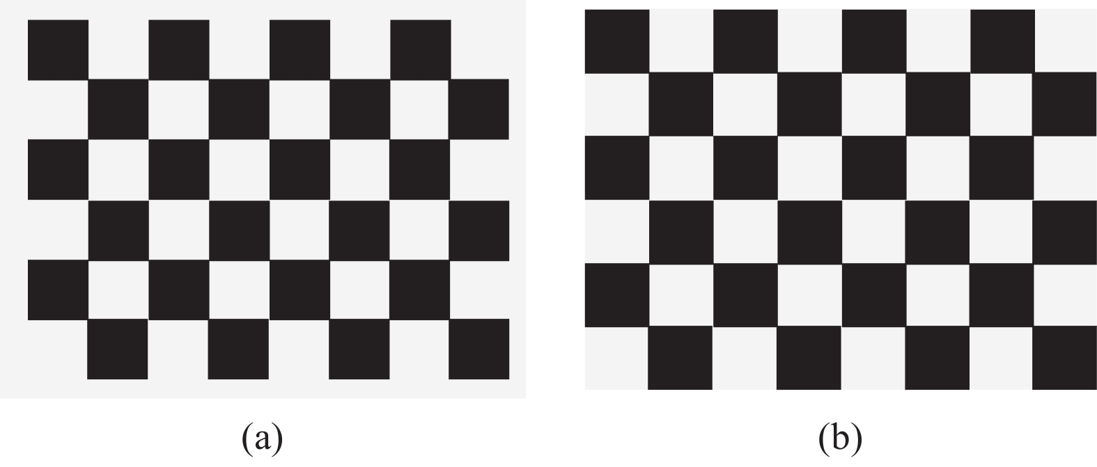
      Figure 6.  (a) Checkerboard with border; (b) Checkerboard without border
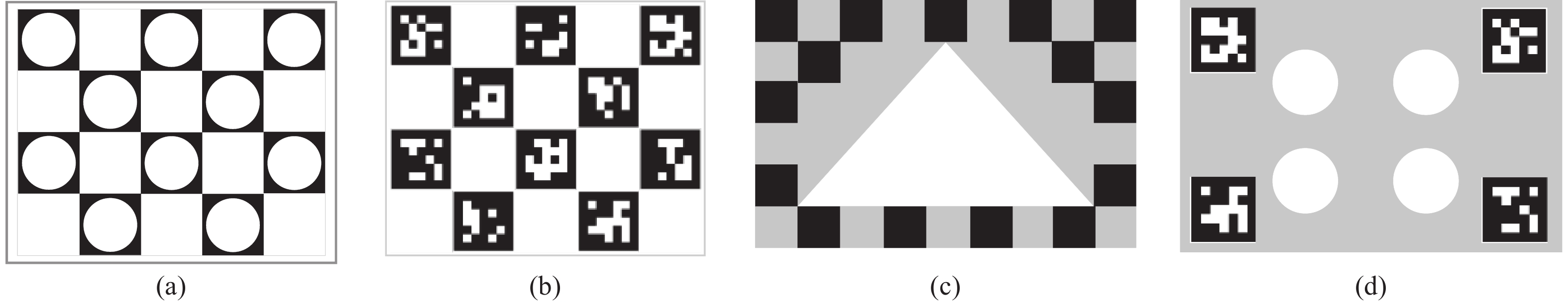
      2) 非棋盘格二维标靶

      为更准确提取标靶特征,提升标定精度,各国学者设计了各种易于识别特征的二维标靶用于激光雷达和相机外参标定,图7为部分非棋盘格二维标靶示例。董方新等[56]设计镂空棋盘标定板,如图7(a)所示,高效计算关键点坐标实现标定任务。但该方法需要稠密的点云数据。俞德崎等[57]利用ArUco标签,如图7(b)所示,确定标定板在激光坐标系与相机坐标系间关系,通过随机采样一致性算法提取标定板角点坐标并建立对应关系方程,最后使用Kabsh算法求解配准参数。韩国学者Ha[58]设计一款中空为三角孔的棋盘格,如图7(c)所示,利用点扫描线在平面板内外边缘4个交点构建关键点完成标定。实验部分通过计算点云与相机点云投影距离评价标定精度,精度可达26.3 mm,标定结果受孔位置和尺寸的影响。Beltrán等[59]设计一款四角ArUco码与中间4个镂空圆结合的标定板,如图7(d)所示,ArUco码确定标定板在相机坐标系的位置,以此位姿计算4个镂空圆心所在相机坐标系的坐标,结合镂空圆心点云坐标计算得到激光雷达和相机外参。实验部分利用不同类型相机和激光雷达标定结果对比,平移误差精度最高达1.12 cm,旋转误差精度达$ 0.34\times {10}^{-2}\;\mathrm{r}\mathrm{a}\mathrm{d} $,该方法对标定板背景要求高。Debattisti等[60]利用多个三角形标定板完成校准,设计虚拟三角板掩膜贴合点云数据提取同名点实现外参标定。但标定环境为室外导致标定精度不高。黄志清等[61]设计单侧透光镂空标定、邓志红等[62]使用特殊镂空棋盘格等二维标靶完成外参标定工作。

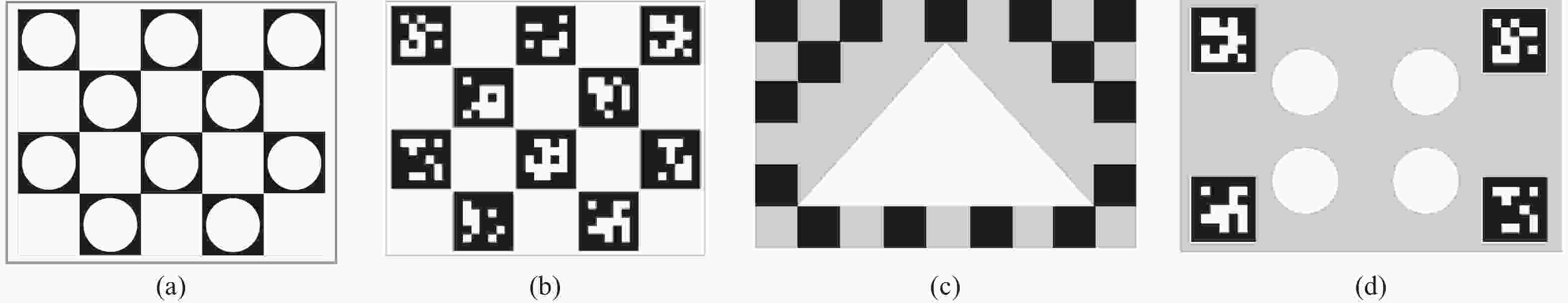
      Figure 7.  Non-checkerboard 2D calibration board

      3) 其他三维标靶

      二维标靶标定激光雷达和相机外参过程丢失空间Z轴约束,计算结果可能造成过拟合,影响标定效果。为解决此问题,各国学者设计了三维标靶对激光雷达和相机外参标定。Chen等[63]使用正立方体棋盘格,不同视角下构建点线约束建立三维特征点到图像边缘参数方程解算标定参数。但该方法需要提取立方体边界三维点,稀疏点云环境中标定效果不理想。Dong等[64]制作特殊非共面V型标定板,提出最小化点到平面距离来获得外参值。该方法对标定物制作精度要求高,增加标定工作量和难度。Pusztai等[65]在自然场景中放置已知尺寸的箱体,计算点云3个相交平面顶点,在箱体尺寸已知条件下得到其他6个角点,以此关键点完成标定。该方法要求箱体7个角点都位于相机和激光雷达视野中,对箱体位姿摆放要求高。最近Fan等[66]设计一款球和空心标定板结合的复合型标定物,利用空心标定板边缘线特征计算初始值,利用球心坐标投影迭代完成标定。该方法平移精度达到0.011 m,旋转误差为0.07°,但方法计算流程复杂,计算效率低。除此之外还有V型棋盘格[67]、对折平面板[68]、球[69]、网格标定物[70]等。这些特殊三维标靶标定结果精度高,但都有特定的应用场景,不具有通用性。

      基于标靶标定可以较容易获取激光雷达和相机的同名特征,计算方法成熟稳定,标定结果精度高。由于该类型标定需要在场景中放置标靶,适用于在静态环境中的离线标定。当传感器间位姿由于抖动等外因发生变化时,需要重新标定,增加标定工作的复杂性。同时该类型标定多需要手工干预,比如摆放标靶位置、裁剪特征点云、标记同名特征等,这为标定工作带来不稳定性,降低标定效率。

    • 无标靶标定是指利用自然场景边缘信息或者图像灰度值与点云强度值的联系完成激光雷达和外参标定。无标靶标定不需要在场景中摆放标靶,标定过程简单,可实现在线标定。可细分为:基于特征信息标定和基于互信息最大化标定。

      1) 基于特征信息标定

      基于特征标定要求相机和激光雷达有重叠的视野,主要针对特征信息明显的环境。常见的特征有区域特征和关键点特征。标定流程是在图像和点云中均找到特定语义区域(如物体边缘、障碍物等),构建目标函数,迭代优化得到外参。Moghadam等[71] 利用自然场景的面交线和边界线特征建立3D-2D线对应关系计算外参。该方法实验部分将点云重投影到图像中,计算均方根误差最高1.85 pixel,标定精度不高,并且对应用场景有十分严格的限制。Scaramuzza等[72]生成点云距离图,根据点云距离图和图像的同名点特征得到标定结果。此方法平均重投影误差为1.6 pixel,标准差为1.2 pixel,但其通过观察选择特征点,计算结果不稳定。Gomez-Ojeda等[73]利用三面正交的场景获取角点,根据点在线、线在面的几何关系构建模型完成标定。该方法计算结果准确,旋转矩阵精度0.292 7°,平移矩阵精度0.426 9 cm,但只能用于含正交三面体的标定环境,影响通用性。Bai等[74]通过激光雷达和相机各坐标系中存在平行线对应的3D-2D消失点得到旋转矩阵,点在线上的约束得到平移矩阵。该方法应用的场景要求具有平行线特征。Kang等[75]利用高斯混合模型框架建立多边缘特征对齐成本函数,通过成本函数极值最小完成标定工作,但边缘特征提取和匹配比较麻烦。Levinson等[76]将点云的深度不连续边界和图像边缘进行匹配。该方法适用于小范围内暴力搜索,搜索范围小。Yuan等[77]提出固定大小体素化、Liu等[78]提出自适应体素化来提取点云深度不连续边界,Wang等[79]提取分割的点云和图像中心,完成激光雷达和相机标定。

      2) 基于互信息最大化

      基于互信息的标定方案是建立激光雷达的强度信息(受激光雷达发射率或者激光雷达发射角影响)和相机图像的灰度值信息关联,使互信息值最大得到的结果就是激光雷达和相机的外参。Abedini等[80]利用SIFT(Scale-Invariant Feature Transform)算法从航空图像和激光雷达强度数据中提取相关信息,匹配图像灰度值和点云强度信息完成外参标定,对点云噪音有一定鲁棒性。Pandney等[81-82]通过激光雷达所测反射率与图像灰度值相关系数,使两者间联合直方图分散最小获得外参标定。在单目相机和激光雷达系统、全向相机和激光雷达系统及单目相机和二维激光雷达系统中分别进行了验证,标定精度易受环境光照影响。Taylor等[83]认为相机图像点对应的三维点法线与相机之间的夹角影响反射强度。通过计算激光雷达点云反射率与上述相机图像点对应角度之间的互信息进行标定,最后利用粒子群算法优化计算。该方法应用于遥感测绘领域中,对不同数据集精度从0.3~1.4 m不等,点云稀疏性和数据源不一致,该标定方法误差较大。宋文松等[84]根据强度关系将点云转化为灰度图,然后提取点云灰度图和相机图同名特征点,匹配计算得标定结果。

      无标靶标定不依赖特定标靶,从自然环境中提取特征信息完成标定。该方法应用灵活,简化标定。但相比于有标靶标定,无标靶标定的精度低,标定结果易受环境信息干扰,稳定性不足。在复杂场景或光照干扰前提下,无标靶标定结果容易出现错误。无标靶标定需要在特定环境下的特定场合进行标定,通用性有待提升。无标靶标定多用自动驾驶大场景信息感知领域,通常采用惯性测量单元配合提高标定精度和鲁棒性。

    • 基于运动标定将相机和激光雷达外参校准视为手眼标定问题,不要求相机和激光雷达有视野重叠,通过传感器的一串移动序列反解标定参数,建模为齐次变换方程的求解问题。基于运动标定属于特殊无标靶标定,多应用于工业机器人领域。该类型标定得到的解存在不同的形式,如四元数形式、对偶四元数形式以及螺旋运动和螺旋轴形式。该方法没有充分考虑测量值不确定性,导致标定精度易受传感器噪声影响,标定精度依赖于环境特征信息,通常采用边缘检测等方式得到特征间对应关系。

      Huang 等[85]提出一种基于Gauss-Helmert估计范式的校准方法,并给出了多传感器运动约束公式。相比于传统最小二乘算法,不仅校准了外部参数,还给出对应位姿观测误差,稳定性和精确性高。Taylor等[86]提出了一套适用于任何系统由激光雷达、相机和导航传感器构成的校准方法。首先对每个传感器的连续帧进行校准,然后利用传感器之间联系实现外部参数校准。Ishikawa等[87]利用光流追踪法跟踪激光雷达在图像平面上的投影点,通过投影误差不断优化缺乏尺度信息的平移向量,标定精度比Taylor等[86]方法高。Zhao等[88]利用相机前后帧图像对城市场景进行三维重建并计算姿态变化,计算激光雷达点云前后帧的最近邻点,得到点云空间变化。杨超等[89]将标定问题建模为观测与预测之间的非线性模型,利用非线性最小二乘方案进行求解,通过误差最小化计算外参。Nedevschi等[90]利用特征匹配检测车辆行使过程传感器之间的偏移量,通过距离变换检测图像边缘特征,将点云转为距离图像提取边缘信息,根据对应边缘信息建立函数调节外参。标定精度中3个方向的平移误差为(0.002, 0.015, −0.005) m,3个轴的旋转误差为(−0.016°, 0.002°, 0.01°)。基于运动标定方法多用于估计初始值或大场景环境下传感器外参调整,标定精度不高。

    • 随着深度学习技术的快速发展,近几年多位学者将其应用于激光雷达与相机外参标定。设计目标函数评价投影后的雷达特征和图像相应特征匹配情况,利用优化方法更新初始外参,逐步迭代改善匹配效果,取匹配效果最好的数据作为标定结果。深度学习特征提取和特征匹配的过程由训练替代,可以根据搜索的数据更新标定结果,相比传统标定方法,自动化程度更高。

      深度学习用于激光雷达和相机外参标定是热门研究领域。卡尔斯鲁厄理工学院的Schneider等[91]第一次将深度学习算法用于解决激光雷达和相机外参标定问题。通过构建的RegNet神经网络分别提取相机图像和激光雷达点云,然后回归计算,完成标定任务。该方法平均角度误差为0.28°,平均移动误差为6 cm,但程序没有开源,最后的验证难以复现。Iyer等[92]设计几何监督深度网络CalibNet,可以实时自动估计3D激光雷达与2D摄像机之间的6自由度刚体变换,减少对校准目标的需求,提高了校准效率,该方法旋转误差0.41°,平移误差4.34 cm。Yuan等[93]提出基于RGGNet的激光雷达和相机外参标定方法,考虑黎曼几何,利用深度生成模型学习隐式容差模型。该方法不仅考虑标定误差,还考虑误差范围内容差,标定效果较好。Lv等[94] 借鉴RegNet和CalibNet深度学习框架,在Loss函数中引入点云距离而计算点云几何结构信息,实现直接输入点云和图像原数据进行端到端训练,是一种精度比较高的在线评定方法。基于深度学习的标定还有CMRNet[95]、CalibRCNN[96]、CalibDNN[97]、CFNet[98]、DXQ-Net[99]、PSNet[100]、ATOP[101]等框架方案。基于深度学习标定是最近几年提出的激光雷达和相机外参解决方案,不需要预先处理点云和图像特征,只需将数据提交神经网络节点寻找潜在关系,可建立两传感器端到端间映射关系。现有深度学习框架下的标定方法多为无监督学习或半监督学习,泛化能力有待提高。

      以上内容为激光雷达与相机外参标定方法的研究现状,文中从有、无标靶等多方面对现有文献阐述说明。为避免不同标定方法交叉,用基于标靶特征(Target Feature)、基于运动(Motion)、基于互信息(Mutual Information)、基于深度学习(Deep Learning)4个方面分析现有标定方法的特点,具体情况如表3所示。Accuracy 表示标定精度,Automaticity 表示自动化性,L表示低,M表示中,H表示高。

      Target featureMotionMutual informationDeep learning
      CharacteristicRequire targets, then calculate pnp based on featuresHand-eye calibration, the accuracy depends on motion estimation of the sensorsCorrelating image grayscale values with point reflectance, and specific applicationsextensive training and poor generalization
      AccuracyHLMM
      AutomaticityLMMH

      Table 3.  Characteristics of different methods for lidar-camera extrinsic calibration

    • 随着自动驾驶、移动机器人、三维建筑模型重建等行业的逐步普及应用,激光雷达和相机信息融合作为该领域重要技术方法是当前研究热点。论文总结激光雷达和相机标定过程所涉及的理论方法,包括相机标定、激光雷达内参标定、激光雷达与相机外参标定。激光雷达外参校准的关键是寻找同名特征和构建特征联系,以此为基础从基于标靶、基于无标靶、基于运动、基于深度学习4个类别归纳现有标定方法及相应特点。由于应用范围广,发展前景好,激光雷达和相机融合标定的研究文献越来越多,总体趋势是实现复杂场景下精确稳定的实时外参标定。近年来,深度学习技术的发展为激光雷达和相机数据融合,也为复杂环境下外参在线校准提新的研究方向。

      激光雷达和相机外参校准的未来方向是在提高校准精度的基础上实现自动化和智能化校准,具体研究内容包括:

      1)提高标定精度。改进特征提取,优化外参求解算法提升传感器间校准精度,从而提高系统感知和定位能力。

      2)增强标定鲁棒性。针对含有噪声、运动模糊、光照变化和遮挡等复杂场景,通过研究新的特征描述子、匹配算法等保证标定结果在复杂场景的鲁棒性。

      3)在线标定。动态环境在线校准传感器位姿是未来趋势,应用场景有无人驾驶、移动机器人等。深度学习训练数据集实现激光雷达和外参标定方法为在线标定提供新方向,但其标定精度需要进提升。

      4)自动化标定。根据环境变化和系统状态调整标定参数,减少人工干预。通过自动化流程和算法,实现快速、准确标定。

      5)标定验证标准制定。为评估不同标定方法优劣,有必要建立统一验证和评估标准。

Reference (101)

Catalog

    /

    DownLoad:  Full-Size Img  PowerPoint
    Return
    Return