Volume 53 Issue 2
Feb.  2024
Turn off MathJax
Article Contents

Du Jiadong, Shan Yong, Zhang Jingzhou. Numerical and experimental research on the effect of outlet structural parameters of diverter nozzle on infrared suppressor performance[J]. Infrared and Laser Engineering, 2024, 53(2): 20230459. doi: 10.3788/IRLA20230459
Citation: Du Jiadong, Shan Yong, Zhang Jingzhou. Numerical and experimental research on the effect of outlet structural parameters of diverter nozzle on infrared suppressor performance[J]. Infrared and Laser Engineering, 2024, 53(2): 20230459. doi: 10.3788/IRLA20230459

Numerical and experimental research on the effect of outlet structural parameters of diverter nozzle on infrared suppressor performance

doi: 10.3788/IRLA20230459
  • Received Date: 2023-07-28
  • Rev Recd Date: 2023-11-08
  • Publish Date: 2024-02-25
  •   Objective  With the rapid development of advanced infrared detection technology and infrared tracking and striking technology, armed helicopters are increasingly threatened by infrared guided missiles from ground and air in the modern high-tech battlefield. In order to improve the battlefield survivability and combat assault capability of armed helicopters, advanced infrared stealth technology must be developed. The research shows that the use of shielding technology and the improvement of the ejector capacity of the suppressor have a significant effect on reducing the infrared radiation intensity of the exhaust system, but the specific technical means should depend on the structure of the infrared suppressor. For the diverter nozzle ejector infrared suppressor, limited to the size and shape of the helicopter, it is difficult to improve the ejector capacity of the diverter nozzle and reduce the exhaust and wall temperature in a limited space. Therefore, it is necessary to discuss the modification scheme of the diverter nozzle outlet to reduce the infrared radiation intensity of the diverter nozzle ejector infrared suppressor.   Methods  A physical model was established including diverter nozzle, gas-collecting chamber, ejected gas inlet, curved mixing tube, covering shelter, and outer cover (Fig.1). The structured and unstructured hybrid grids were established, and the infrared radiation of the infrared suppressor was calculated by the forward-backward ray-tracing method. The calculation method is verified by experimental data (Tab.1-2,Fig.9). By comparing the pumping coefficient, total pressure recovery coefficient, outlet and wall temperature distribution of the mixing tube and infrared radiation intensity of the diverter nozzle ejector infrared suppressor (Fig.10-14), the effect of outlet structural parameters of diverter nozzle on infrared suppressor performance is analyzed from multiple perspectives.   Results and Discussions   The experimental data are used to verify the calculation method. The pumping coefficient and total pressure recovery coefficient of the infrared suppressor under different diverter nozzle outlet structures are compared and analyzed (Fig.10). The exhaust temperature distribution of the mixing tube outlet plane of the infrared suppressor under different diverter nozzle outlet structures is shown (Fig.11). The temperature distribution of the outer mixing tube wall surface of the infrared suppressor under different diverter nozzle outlet structures is shown (Fig.12). And the infrared radiation intensity distribution of the infrared suppressor with different diverter nozzle outlet configurations on the horizontal and lead hammer detection surfaces in the 3-5 μm band (Fig.13) and 8-14 μm band is shown (Fig.14).   Conclusions  Compared with the original model, the pumping coefficient of the Lobe_1 with a certain expansion angle is slightly reduced, the total pressure recovery coefficient of the Lobe_1 is reduced, and the peak exhaust temperature at the outlet of the intermediate mixing tube is reduced by 65.1 K. For Lobe_1, the wall temperature in the upper and lower areas of the mixing tube is reduced, but the temperature in the local area of the outer wall of the middle and rear sections of the mixing tube is increased. The lobed outlet structural (Lobe_2) with an outer expansion angle of 0 increases the pumping coefficient by 3.8%. The total pressure recovery coefficient is basically the same as that of the Lobe_1 model, and the peak exhaust temperature of the intermediate mixing tube is also reduced by 62.8 K, especially the effect of reducing the wall surface temperature of the mixing tube is the best. The outlet of the diverter nozzle with tab structure increases the pumping coefficient by 10.6%, but the total pressure recovery coefficient decreases 0.7%, and the average exhaust temperature of the inner mixing tube decreases by 19.3 K. Tab model has a poor effect on cooling the wall temperature of the mixing tube. In general, both lobe and tab structures play a role in ejection and mixing. In particular, the lobed outlet structure (Lobe_2) has the best effect on reducing the overall infrared radiation of the suppressor, and the infrared radiation intensity in the 3-5 μm band can be reduced by up to 21%, in the 8-14 μm band, the infrared radiation intensity can be reduced by 15%.
  • [1] Mahulikar S P, Sonawane H R, Rao G A. Infrared signature studies of aerospace vehicles [J]. Progress in Aerospace Sciences, 2007, 43(7-8): 218-245. doi:  10.1016/j.paerosci.2007.06.002
    [2] Rao G A, Mahulikar S P. New criterion for aircraft susceptibility to infrared guided missiles [J]. Aerospace Science and Technology, 2005, 9(8): 701-712. doi:  10.1016/j.ast.2005.07.005
    [3] Mahulikar S P, Sane S K, Gaitonde U N. Numerical studies of infrared signature levels of complete aircraft [J]. The Aeronautical Journal, 2001, 105(1046): 185-192. doi:  10.1017/S0001924000025422
    [4] Ren Lifeng, Zhang Jingzhou, Wang Xianwei, et al. Analysis of stealth properties on IR radiation suppressor embed inside helicopter rear airframe [J]. Infrared and Laser Engineering, 2011, 40(11): 2091-2097. (in Chinese)
    [5] Fang Renyu, Zhang Jingzhou, Shan Yong. Effects of sheltering baffles on the infrared radiation characteristics of two-dimensional nozzles [J]. Journal of Aerospace Power, 2011, 26(2): 343-348. (in Chinese)
    [6] Liu Changchun, Ji Honghu. Experiment on infrared radiation characteristics of S shaped 2D nozzle [J]. Journal of Aerospace Power, 2019, 34(7): 1493-1500. (in Chinese)
    [7] Rogalski A. Competitive technologies of third generation infrared photon detectors [J]. Opto-Electronics Review, 2006, 14(1): 84-98.
    [8] Wang Hao, Ji Honghu, Sang Xueyi. Effects of fully shielded guiding strut on infrared signatures of exhaust system [J]. Journal of Aerospace Power, 2020, 35(10): 2078-2088. (in Chinese)
    [9] Bettini C, Cravero C, Cogliandro S. Multidisciplinary analysis of a complete infrared suppression system [J]. ASME Paper, 2007, 6: 1365-1370.
    [10] Chen Suqi, Shan Yong, Zhang Jingzhou, et al. Effect of baffle configuration on aerodynamic and infrared radiation characteristics of helicopter infrared suppressor [J]. Infrared and Laser Engineering, 2022, 51(8): 20210659. (in Chinese) doi:  10.3788/IRLA20210659
    [11] Wu Zhongcheng, Shan Yong, Zhang Jingzhou, et al. Study on heat transfer enhancement and ejection characteristics of mixing pipe with ribs for infrared suppressor[J/OL]. [2024-01-23] https://doi.org/10.13700/j.bh.1001-5965.2022.0548.
    [12] Song Jian, Shan Yong, Zhang Jingzhou. Study on the cooling and infrared radiation characteristics of the double-layer mixing tube exhaust outlet diversion shielding [J]. Journal of Aerospace Power, 2024, 39(5): 20220374. (in Chinese)
    [13] Pan Chengxiong, Zhang Jingzhou, Shan Yong, et al. Numerical research on aerodynamic characteristics inside single-stage ejection and multi-nozzles infrared system of helicopter [J]. Journal of Aerospace Power, 2010, 25(5): 1025-1030. (in Chinese)
    [14] Zhang Boan. Study on Aerodynamic and Infrared Radiation Characteristics of Infrared Suppressors with Multi-nozzles Ejector[D]. Nanjing: Nanjing University of Aeronautics and Astronautics, 2020. (in Chinese)
    [15] Pan Chengxiong, Shan Yong, Zhang Jingzhou. Parametric effects on internal aerodynamics of lobed mixer-ejector with curved mixing duct [J]. Journal of Engineering for Gas Turbines and Power, 2014, 136(6): 061504. doi:  10.1115/1.4026426
    [16] Yang Zhongyao, Zhang Jingzhou, Shan Yong. Suppression of exhaust plume infrared and jet noise of large aspect ratio curved mixing duct [J]. Acta Aeronautica et Astronautica Sinica, 2023, 44(5): 126848. (in Chinese)
    [17] Chen Geng, Shan Yong, Tan Xiaoming, et al. Effects of mixing duct geometric parameters on flow dynamics and infrared radiation characteristics for IR suppressor [J]. Infrared and Laser Engineering, 2015, 44(12): 3597-3603. (in Chinese)
    [18] Chen Geng, Tan Xiaoming, Shan Yong, et al. Impacts of two-dimensional curved mixing duct exit geometric parameters on flow dynamics and infrared radiation characteristics for IR suppressor [J]. Infrared and Laser Engineering, 2015, 44(6): 1704-1711. (in Chinese)
    [19] Pan Chengxiong, Shan Yong, Zhang Jingzhou. Modeling and analysis of helicopter thermal and infrared radiation [J]. Chinese Journal of Aeronautics, 2011, 24(5): 558-567. doi:  10.1016/S1000-9361(11)60065-4
    [20] Yang Zhongyao, Zhang Jingzhou, Shan Yong. Research on the influence of integrated infrared suppressor exhaust angle on exhaust plume and helicopter infrared radiation [J]. Aerospace Science and Technology, 2021, 118: 107013. doi:  10.1016/J.AST.2021.107013
    [21] Ji Jingyuan, Zhang Jingzhou, Shan Yong, et al. Investigation on aerodynamic and infrared characteristics of spherical convergent two-dimensional vectoring nozzle: simulating ground status [J]. Journal of Aerospace Power, 2017, 32(3): 614-620. (in Chinese)
    [22] Li Jianxun, Tong Zhongxiang, Liu Wanjun, et al. Infrared radiation characteristic experiment and simulation of aeroengine [J]. Infrared and Laser Engineering, 2013, 42(3): 549-555. (in Chinese)
  • 加载中
通讯作者: 陈斌, bchen63@163.com
  • 1. 

    沈阳化工大学材料科学与工程学院 沈阳 110142

  1. 本站搜索
  2. 百度学术搜索
  3. 万方数据库搜索
  4. CNKI搜索

Figures(14)  / Tables(2)

Article Metrics

Article views(73) PDF downloads(36) Cited by()

Related
Proportional views

Numerical and experimental research on the effect of outlet structural parameters of diverter nozzle on infrared suppressor performance

doi: 10.3788/IRLA20230459
  • Key Laboratory of Thermal Management and Energy Utilization of Aircraft, Ministry of Industry and Information Technology, College of Energy and Power, Nanjing University of Aeronautics and Astronautics, Nanjing 210016, China

Abstract:   Objective  With the rapid development of advanced infrared detection technology and infrared tracking and striking technology, armed helicopters are increasingly threatened by infrared guided missiles from ground and air in the modern high-tech battlefield. In order to improve the battlefield survivability and combat assault capability of armed helicopters, advanced infrared stealth technology must be developed. The research shows that the use of shielding technology and the improvement of the ejector capacity of the suppressor have a significant effect on reducing the infrared radiation intensity of the exhaust system, but the specific technical means should depend on the structure of the infrared suppressor. For the diverter nozzle ejector infrared suppressor, limited to the size and shape of the helicopter, it is difficult to improve the ejector capacity of the diverter nozzle and reduce the exhaust and wall temperature in a limited space. Therefore, it is necessary to discuss the modification scheme of the diverter nozzle outlet to reduce the infrared radiation intensity of the diverter nozzle ejector infrared suppressor.   Methods  A physical model was established including diverter nozzle, gas-collecting chamber, ejected gas inlet, curved mixing tube, covering shelter, and outer cover (Fig.1). The structured and unstructured hybrid grids were established, and the infrared radiation of the infrared suppressor was calculated by the forward-backward ray-tracing method. The calculation method is verified by experimental data (Tab.1-2,Fig.9). By comparing the pumping coefficient, total pressure recovery coefficient, outlet and wall temperature distribution of the mixing tube and infrared radiation intensity of the diverter nozzle ejector infrared suppressor (Fig.10-14), the effect of outlet structural parameters of diverter nozzle on infrared suppressor performance is analyzed from multiple perspectives.   Results and Discussions   The experimental data are used to verify the calculation method. The pumping coefficient and total pressure recovery coefficient of the infrared suppressor under different diverter nozzle outlet structures are compared and analyzed (Fig.10). The exhaust temperature distribution of the mixing tube outlet plane of the infrared suppressor under different diverter nozzle outlet structures is shown (Fig.11). The temperature distribution of the outer mixing tube wall surface of the infrared suppressor under different diverter nozzle outlet structures is shown (Fig.12). And the infrared radiation intensity distribution of the infrared suppressor with different diverter nozzle outlet configurations on the horizontal and lead hammer detection surfaces in the 3-5 μm band (Fig.13) and 8-14 μm band is shown (Fig.14).   Conclusions  Compared with the original model, the pumping coefficient of the Lobe_1 with a certain expansion angle is slightly reduced, the total pressure recovery coefficient of the Lobe_1 is reduced, and the peak exhaust temperature at the outlet of the intermediate mixing tube is reduced by 65.1 K. For Lobe_1, the wall temperature in the upper and lower areas of the mixing tube is reduced, but the temperature in the local area of the outer wall of the middle and rear sections of the mixing tube is increased. The lobed outlet structural (Lobe_2) with an outer expansion angle of 0 increases the pumping coefficient by 3.8%. The total pressure recovery coefficient is basically the same as that of the Lobe_1 model, and the peak exhaust temperature of the intermediate mixing tube is also reduced by 62.8 K, especially the effect of reducing the wall surface temperature of the mixing tube is the best. The outlet of the diverter nozzle with tab structure increases the pumping coefficient by 10.6%, but the total pressure recovery coefficient decreases 0.7%, and the average exhaust temperature of the inner mixing tube decreases by 19.3 K. Tab model has a poor effect on cooling the wall temperature of the mixing tube. In general, both lobe and tab structures play a role in ejection and mixing. In particular, the lobed outlet structure (Lobe_2) has the best effect on reducing the overall infrared radiation of the suppressor, and the infrared radiation intensity in the 3-5 μm band can be reduced by up to 21%, in the 8-14 μm band, the infrared radiation intensity can be reduced by 15%.

    • 武装直升机作为现代化最主要的飞行兵器之一,因其反应灵活,机动性好,能贴地飞行,隐蔽性好,生存能力强,机载武器的杀伤威力大,在局部战争和特殊任务的执行中发挥日益重要的作用[1]。随着先进红外探测技术与红外跟踪打击技术的高速发展,在现代化高科技战场环境中,武装直升机受到来自地面和空中红外制导导弹的威胁越来越大[2-3],为了提高武装直升机的战场生存能力和作战突击能力,必须发展先进的红外隐身技术[4]

      目前针对直升机排气系统的红外抑制方法主要有:1)遮挡技术,通过遮挡红外辐射源,以达到降低或避免其被红外探测器直接探测到的机会,如范仁钰等[5]通过在二元喷管出口处安装带气膜冷却的双层遮挡板结构,有效抑制了排气系统的红外辐射强度;刘常春等[6]实验测量了S弯二元喷管和基准轴对称喷管的红外辐射强度,得到S弯二元喷管有着明显的红外抑制作用;Rogalski[7]将引射混合管设计为弯曲构型,实现对腔体中高温部件的遮挡;王浩等[8]针对末级涡轮叶片设计了带气膜冷却的全遮挡导流支板结构,有效对涡轮高温壁面进行遮挡,显著降低排气系统的红外辐射强度,抑制了末级涡轮对红外辐射的贡献。2)利用高温主流的排气动能引射环境冷气,以降低排气温度和壁面温度,如Bettini等[9]在分流喷管表面开设百叶窗型的引射入口,有效降低了混合管的壁面温度和排气温度;陈苏麒等[10]设计具有引射结构的挡板结构,提高了二元引射喷管的引射系数,有效降低红外抑制器的壁面和气体红外辐射强度;吴忠诚等[11]研究了在红外抑制器外侧单根混合管表面加装肋片和遮挡罩外侧狭缝进气面积的影响,有效降低了遮挡罩壁面平均温度;宋健等[12]设计了一种双层混合管排气出口导流结构,有效降低了壁面高温区温度和混合管及其排气的总体红外辐射强度。以上研究表明,使用遮挡技术和提升抑制器的引射能力对降低排气系统红外辐射强度有着显著效果,但具体采用何种技术手段应视红外抑制器结构而定。

      分流喷管引射式红外抑制器[13-14]将发动机排气分成平行三股,利用排气动能引射环境冷气进入三个独立的混合管在其内掺混降温,该抑制器结构增加了引射和混合边界,从而有效增强了抑制器的引射能力。潘丞雄等[13]模拟和分析了多路分流排气引射系统各支路引射混合管的引射能力、总压恢复系数和出口速度及压力的差异;张伯安[14]系统地研究了分流喷管引射式红外抑制器,采用辐射遮挡罩和弯曲混合管的遮挡技术。然而,受限于红外抑制器在直升机上的尺寸和形状,在有限空间内提高分流喷管引射能力、降低排气和壁面温度难度大。因此,文中提出分流喷管出口修型方案,设计了抑制器缩比实验模型。利用实验数据对计算方法进行验证,通过对比分流喷管引射式红外抑制器的引射系数、总压恢复系数、混合管的出口和壁面温度分布和红外辐射强度,多角度地分析了分流喷管出口构型对红外抑制器的性能影响。

    • 分流喷管引射式红外抑制器物理模型如图1所示,包括分流喷管、集气腔、百叶窗型引射入口、弯曲混合管、遮挡罩、蒙皮等。图1(a)为分流喷管引射式红外抑制器的具体结构示意图及装配在直升机上的具体位置示意,发动机动力涡轮后的高温燃气进入四根分流喷管,其中,流经外侧喷管的高温燃气进入外侧混合管;经过中间两根喷管(图1(c)中间的上下两根喷管)的高温燃气进入中间混合管;进入内侧喷管的高温燃气流入内侧混合管,并利用高温燃气的排气动能引射环境冷气从引射入口进入集气腔后与高温燃气在弯曲混合管内充分掺混冷却后排出,红外抑制器的弯曲混合管后段与X轴正方向夹角为20°,可以对高温的分流喷管部件进行遮挡,并在弯曲混合管外侧布置辐射遮挡罩以避免高温混合管直接向蒙皮传递热量,如图1(b)所示。红外抑制器的分流喷管结构示意图如图1(c),由四根独立的喷管组成,分流喷管的出口面积与入口面积相等,其出口平面的法线方向与弯曲混合管前段平行。

      Figure 1.  (a) Diverter nozzle ejector infrared suppressor;(b) Top view of infrared suppressor;(c) Diverter nozzle (tail perspective)

      图2为分流喷管不同出口构型的二维结构示意图,以分流喷管出口为跑道型的红外抑制器作为基准模型(Origin),如图2(a)所示。图2(b)和图2(c)展示了两种波瓣出口的结构和尺寸,两种波瓣的瓣宽均为20 mm,其中Lobe_1的内扩张角与外扩张角相等,Lobe_2的外扩张角为0°。图2(d)展示了带突片的喷口结构和尺寸,突片是一个斜边为20 mm的等腰直角三角形,后倾角为60°。值得注意的是虽然各模型的分流喷管出口结构存在差异,但喷管出口面积保持一致。

      Figure 2.  Outlet structural parameters of diverter nozzle

    • 红外抑制器分流喷管进口定义为流量进口边界,质量流量为6.17 kg/s,总温为842 K,并假定排气热力参数在分流喷管均匀。为了模拟分流喷管引射式红外抑制器从外界引射环境冷气,且保证混合管排气充分发展,在红外抑制器外围构建了足够大的外流场区域,如图3所示,外流场边界设置为压力出口,压力为101 325 Pa,外流场环境冷气温度为288.15 K。

      Figure 3.  Schematic diagram of the computational domain

      假定来自发动机动力涡轮后的排气是完全燃烧的燃气,主要为氮气、二氧化碳和水蒸气,其质量占比为0.706、0.209、0.085。引射的环境冷气组成成分为氮气和氧气,质量占比分别为0.756和0.244[15-16]。红外抑制器的固体壁面设置为无滑移的流固耦合面进行传热计算,同时考虑固体壁面之间的辐射换热,红外抑制器的固体壁面发射率取为0.8。

      采用ICEM (Integrated Computer Engineering and Manufacturing)软件对计算模型进行网格划分。由于分流喷管引射式红外抑制器整体结构较为复杂,且外流场区域尺寸较大,综合考虑计算效率与精度,对红外抑制器结构使用适应能力较强的非结构化网格进行网格划分,并对分流喷管、混合管等壁面区域进行局部网格加密处理,对大的外部流场使用结构化网格进行网格划分。如图4所示,对比红外抑制器网格数量为580万、660万、750万、830万和920万下的引射系数和总压恢复系数,最终确定总体的网格数约为750万。
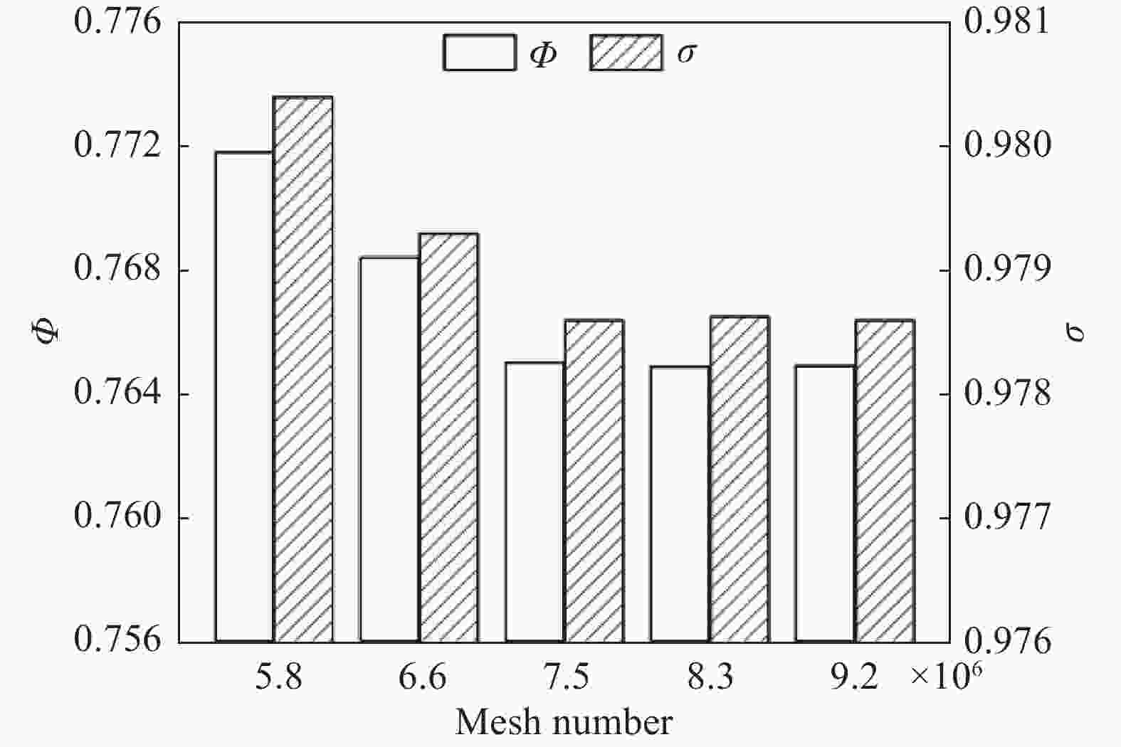
      Figure 4.  Computed results of Infrared suppressor pumping coefficient and total pressure recovery coefficient under different grid numbers

      参考大量红外抑制器的数值模拟文献[10-18],选用SST (Shear Stress Transfer) k-w湍流模型进行数值模拟,加入组分输运方程获得主流与次流掺混后的组分分布。流动传热与组分输运方程中的对流项和扩散项均采用二阶迎风差分格式离散,压力与速度耦合采用SIMPLEC (Semi-Implicit Method for Pressure-Linked Equations Consistent)算法。选取离散坐标辐射模型(DO模型)计算辐射换热。计算收敛判据设置为各项残差均小于10−5

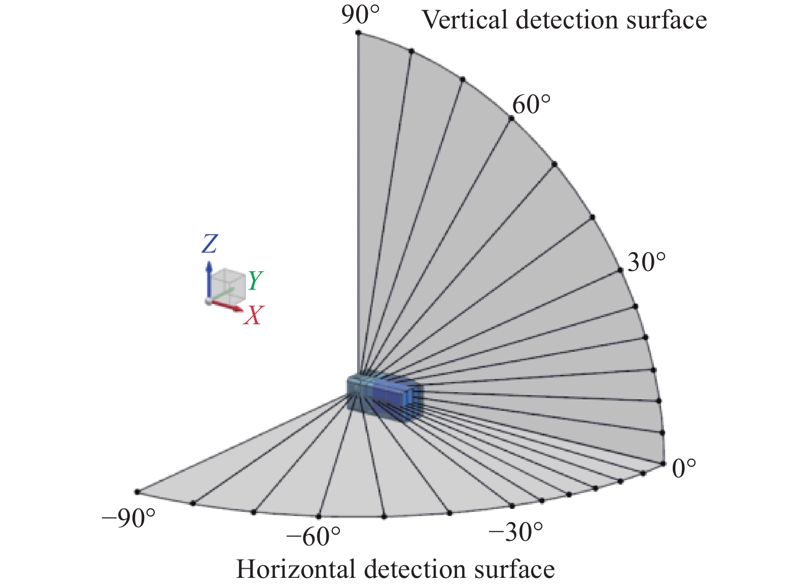
    • 在流场和温度场计算的基础上,红外辐射特性计算采用经过验证的正反射线追踪法[19-20]。文中计算和分析了分流喷管引射式红外抑制器3~5 μm波段和8~14 μm波段的红外辐射特性。考虑红外抑制器结构在铅锤方向上的对称性以及内侧被机身遮挡,因此将探测点设置在水平探测面−90°~0°和铅锤探测面0°~90°范围内,其中正对混合管排气出口的水平探测面−30°~0°和铅锤探测面0°~30°范围每5°一个探测点,水平探测面−90°~−30°和铅锤探测面30°~90°范围每10°一个探测点,探测距离为200 m,红外辐射特性计算时红外探测点位置分布如图5所示。

      Figure 5.  Schematic diagram of infrared detection position distribution

    • 引射系数Φ是衡量红外抑制器的分流喷管引射能力的重要参数,定义如下[21]

      式中:mb为通过百叶窗入口进入的引射次流流量;m为主流流量。

      主流与引射次流的掺混势必造成排气的流动损失,从而直接影响发动机的性能,因此引入总压恢复系数对此进行评价。总压恢复系数σ定义为[10]

      式中:moutmmb分别为混合管出口流量、主流流量和引射次流流量;PoutPPb分别为混合管出口、主流入口和百叶窗引射入口的总压。

    • 图6为实验系统示意图,主流从离心式压气机流出,经燃烧室燃烧后进入稳流段,最后进入实验段。主流通道设有流量计,可以监控实验的主流流量。根据数值计算模型,设计了基准模型和两种波瓣出口模型的1/2缩比实验,三种喷管出口实物如图7所示。抑制器分流喷管主流流量为0.3 kg/s,温度为773 K。

      Figure 6.  Schematic diagram of experimental system

      Figure 7.  Photograph of diverter nozzle (tail perspective)

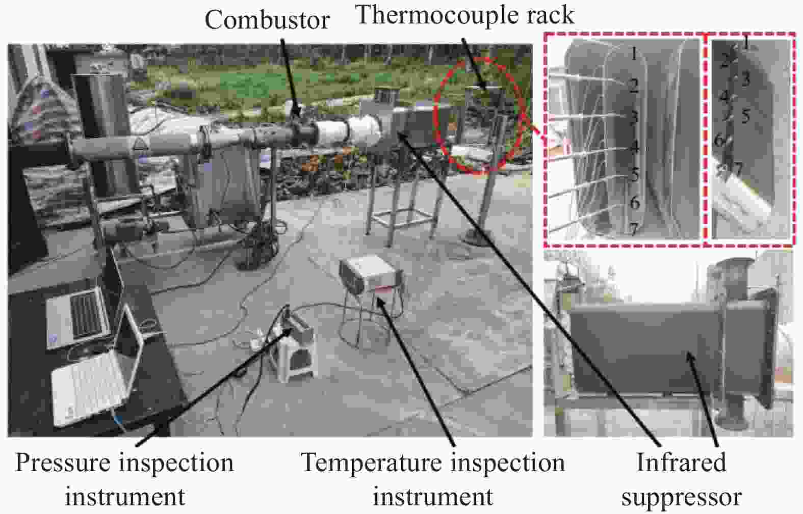
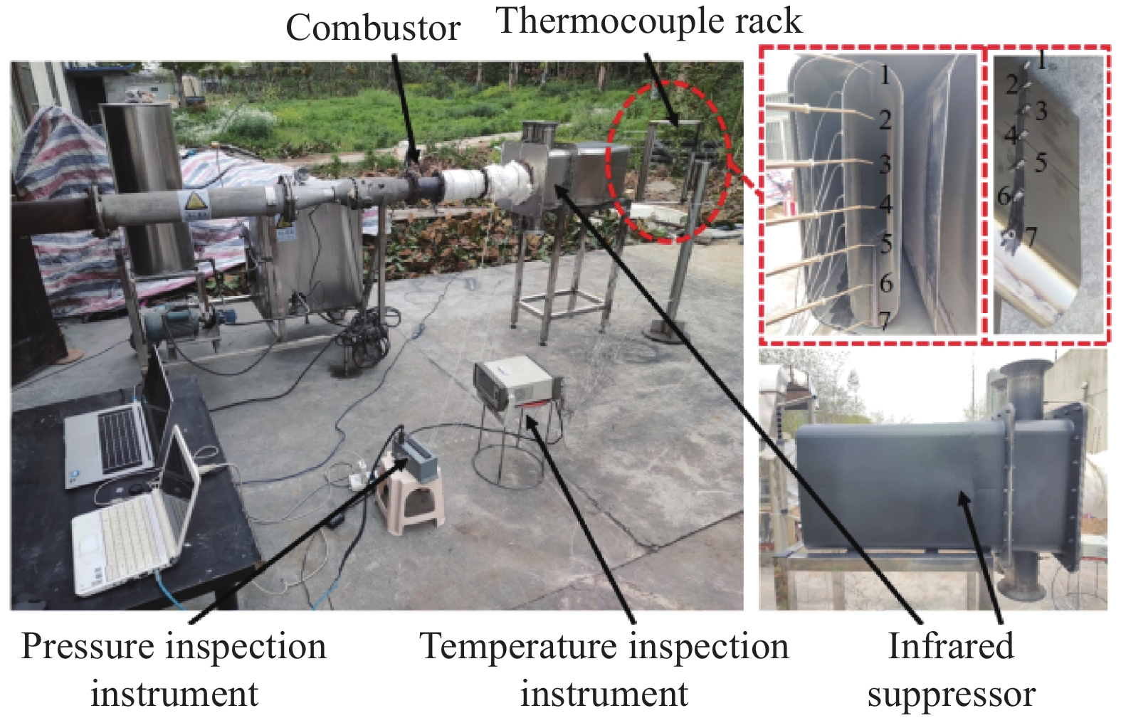
    • 图8为实验系统实物图,引射系统由四根吸风喇叭管和集气腔组成,在吸风喇叭管内布置了静压测量点,弯曲混合管的引射流量通过测量的静压换算而得,压力采集设备为PSI (Pressure Scanner Implement) 9116智能压力扫描阀,测量误差在0.05%以内。混合管的出口温度通过铁制热电偶耙测量,竖向共分布有7根热电偶,每根热电偶之间间隔约5 cm。内侧混合管壁面温度通过预留的测点测量,测点位置距离混合管出口平面10 cm,测量时将热电偶插入旋紧即可,竖向共分布有7根热电偶,每根热电偶之间间隔约5 cm,热电偶耙实物图和热电偶测量位置如图8所示,温度采集设备为多路温度测试仪(anbai-AT4764),测量误差在±0.5 K以内。测量红外辐射强度的设备为红外遥感光谱辐射计(VSR-3),测量误差在3%以内,探测点位于为实验模型的−90°方向(参考图5),距离实验段40 m。

      Figure 8.  Photograph of experimental system

    • 对实验工况下的实验模型进行数值模拟。实验模型引射系数的实验结果与仿真结果如表1所示。可以得到,相比Origin模型,Lobe_2模型引射系数的实验结果基本不变,Lobe_1模型引射系数的实验结果明显降低;缩比模型引射系数的数值结果与实验结果吻合度高,误差在4%以内。

      ModelExperimentSimulationDeviation
      Origin0.9880.9751.32%
      Lobe_10.8960.9253.24%
      Lobe_20.9811.0183.77%

      Table 1.  Pumping coefficient of experimental model

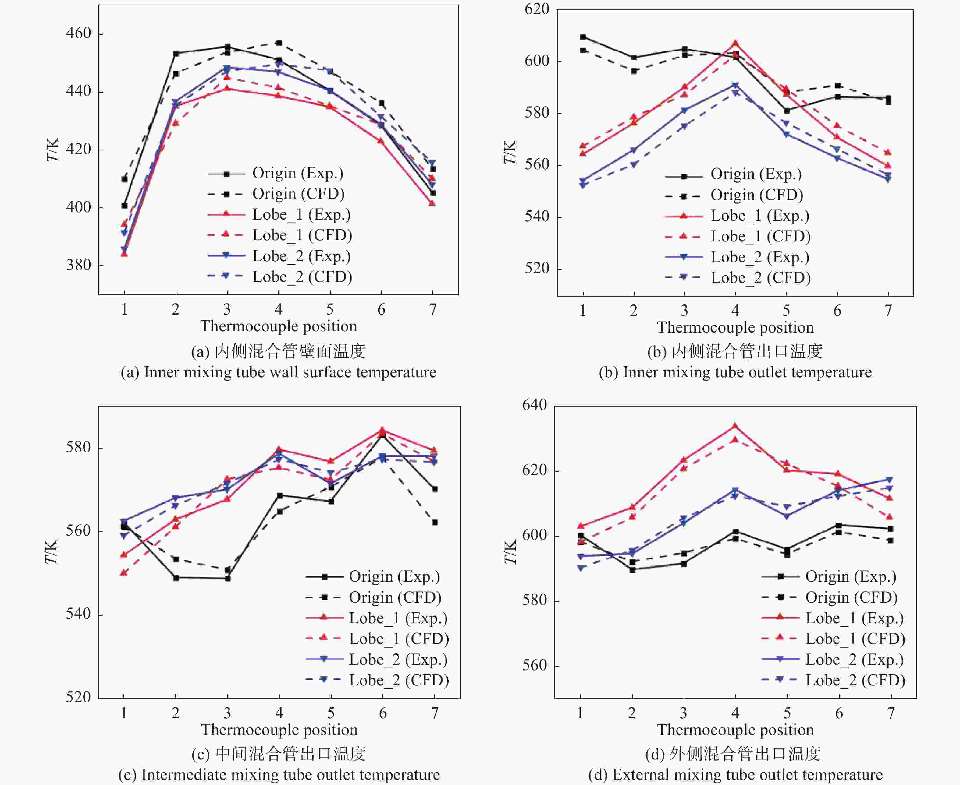
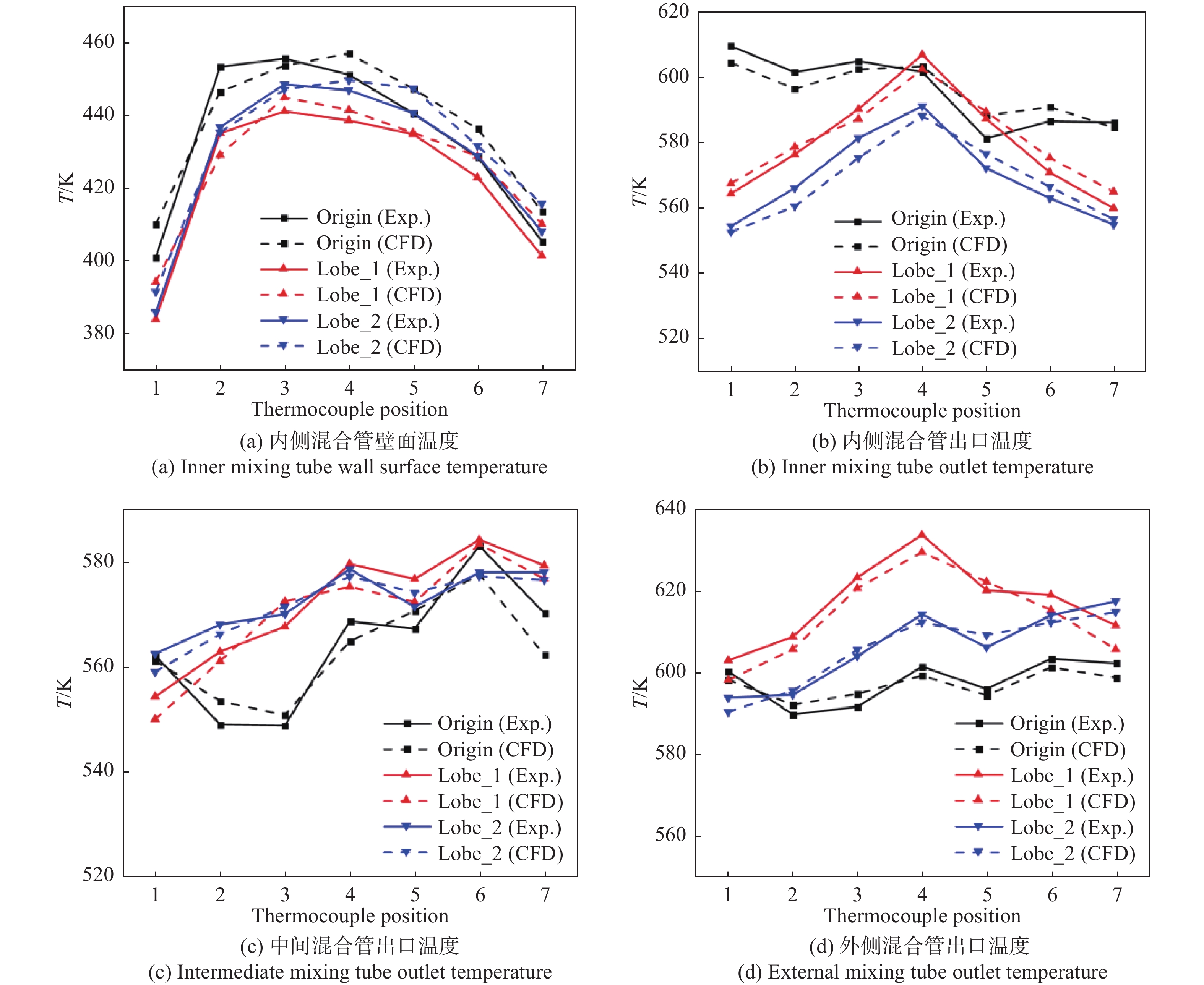
      图9为实验模型内侧混合管壁面与混合管出口温度分布的实验与数值模拟结果对比。三组实验的内侧混合管壁面温度在1号热电偶位置的数值模拟结果均高于实验结果,并存在较大误差,最大误差达到10%,造成误差的原因在于1号热电偶未旋紧到与混合管壁面良好接触,其他位置的数值模拟结果与实验结果吻合度较高,误差在8%以内。数值模拟和实验测量得到的混合管排气出口温度分布趋势一致,误差基本在5%以内。

      表2为实验模型的红外辐射强度。数值模拟和实验测量得到的红外辐射强度变化趋势一致,两者最大误差为6.42%,最小差值为2.98%,吻合程度较高。总体来看,数值模拟结果与实验测量结果吻合度较高,满足工程计算需求[22]

      Figure 9.  Comparison of experimental and numerical simulation results of experimental model temperature distribution

      Model3-5 μm infrared radiation intensity/W·sr–1 8-14 μm infrared radiation intensity/W·sr–1
      ExperimentSimulationDeviationExperimentSimulationDeviation
      Origin0.4070.4295.41% 3.2853.1872.98%
      Lobe_10.4200.4363.81%2.9583.0733.89%
      Lobe_20.3580.3816.42%2.4642.5945.28%

      Table 2.  Infrared radiation intensity of experimental model

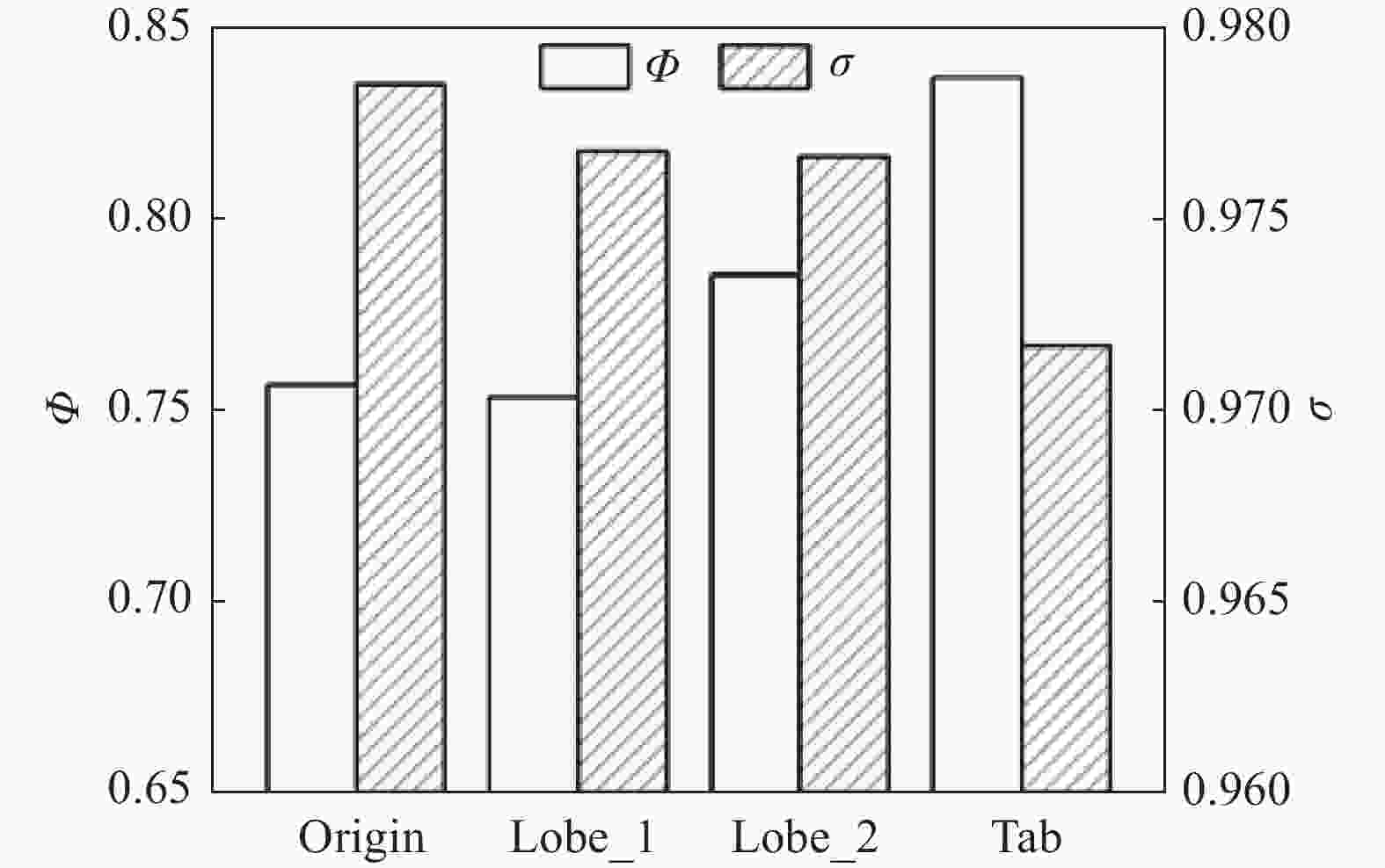
    • 图10为不同分流喷管出口结构下的红外抑制器引射系数和总压恢复系数。可以看出Lobe_1模型的引射系数相比基准模型(Origin)的引射系数略有降低,这是因为在保证喷管出口面积相同的条件下,喷管与混合管之间的引射通道减小,且带有一定外扩张角的波瓣结构使得主流流出后尚未完全发展便触附混合管壁面,从而造成卷吸次流的面积减少,其总压恢复系数由于主流碰壁以及同次流的掺混略微降低。Lobe_2模型采用了外扩张角为0的波瓣结构,使主流得以在混合管内充分发展,主流动量被充分利用,相比基准模型(Origin),其引射系数增大了3.8%,总压恢复系数相比Lobe_1模型基本不变。Tab模型有着比Lobe_1和Lobe_2模型更大的引射通道,同时在三角形突片强化气流掺混的双重作用下,拥有相比其他结构更高的引射系数,相比基准模型(Origin),其引射系数增大了10.6%,但总压恢复系数在主流冲击突片和同次流的掺混作用下下降明显。

      Figure 10.  The influence of the diverter nozzle outlet configuration on the pumping coefficient and total pressure recovery coefficient of the infrared suppressor

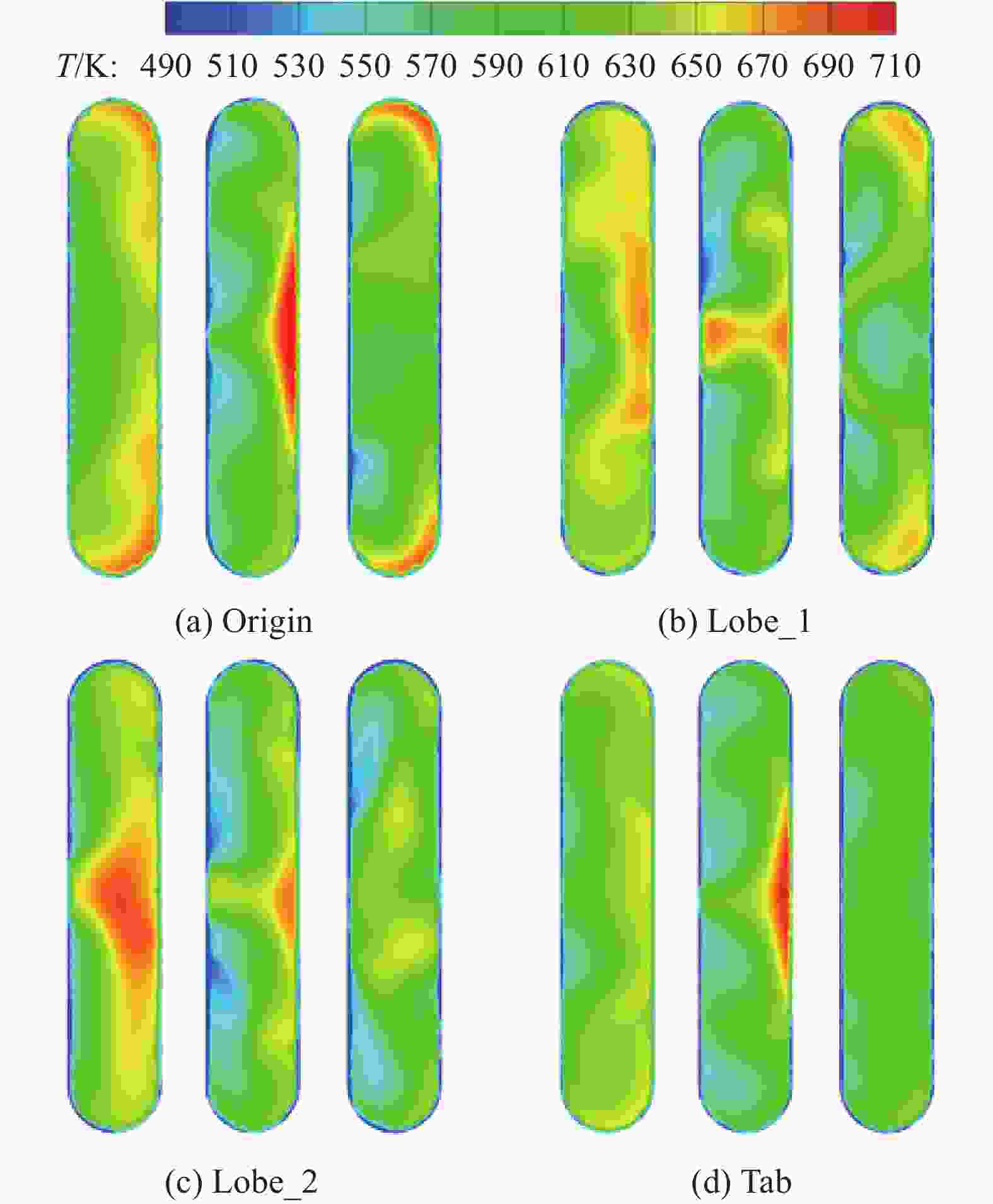
    • 图11展示了不同分流喷管出口结构下红外抑制器的混合管出口平面排气温度分布,从左到右依次为外侧混合管、中间混合管和内侧混合管的出口平面排气温度分布。可以看出由于混合管向左侧(外侧)偏转,高温排气冲刷混合管右侧壁面造成右半区域出现高温区。图11(a)为基准模型(Origin)的混合管出口平面排气温度分布,三根混合管出口均存在局部高温区,尤其是中间混合管的出口排气平均温度和最高温度分别为612.5 K和745.3 K,可见基准喷管的气流掺混能力差。图11(b)和11(c)分别为Lobe_1模型和Lobe_2模型的混合管出口平面排气温度分布,相比基准模型(Origin),带波瓣出口的分流喷管结构有助于增强主流与次流的掺混,有效降低了混合管的出口排气最高温度,其中Lobe_1模型的中间混合管出口排气最高温度降低到680.2 K,降低了65.1 K;Lobe_2模型在降低了中间混合管出口排气最高温度的同时将出口排气平均温度降低到607.7 K,降低了4.8 K。由于喷管伸入外侧混合管较长,且为保证喷管出口面积相同,Lobe_2模型的外侧混合管引射通道面积减小较大,外侧混合管的中右侧壁面仍存在高温区,但相比基准模型(Origin)其出口排气平均温度从636.6 K降低到634.7 K,降低了1.9 K。图11(d)为Tab模型的混合管出口平面排气温度分布,其中间混合管出口排气温度分布特征与基准模型(Origin)相似,带突片出口结构的红外抑制器由于有着更高的引射系数,有效降低了混合管的出口排气平均温度,相比基准模型(Origin)其内侧混合管出口排气平均温度降低到595.0 K,降低了19.3 K,虽然在四种模型中其出口排气平均温度最低,但中间混合管右侧壁面区域仍存在高温区,最高温度为716.8 K。

      Figure 11.  Outlet temperature distribution of the infrared suppressor mixing tube

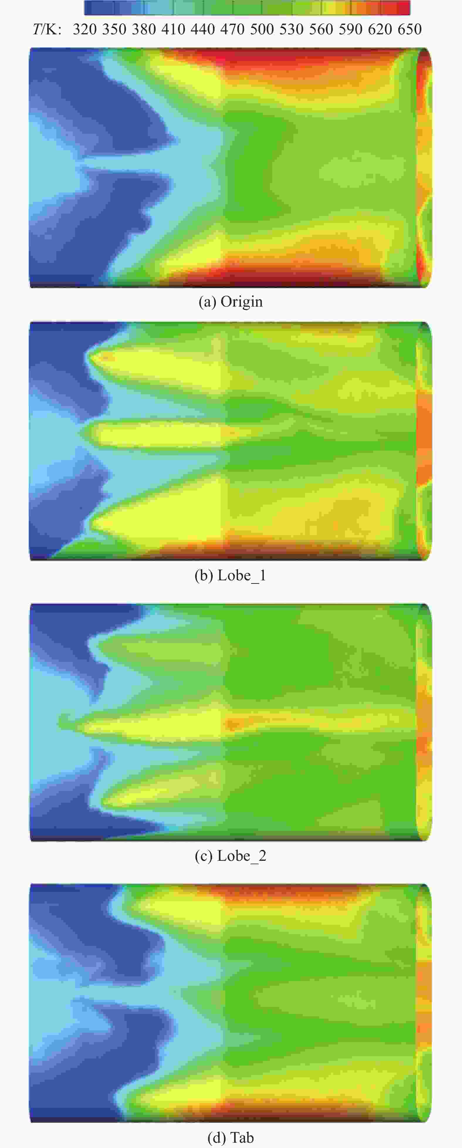
      红外抑制器的混合管(尤其是外侧混合管)温度的分布和大小直接影响蒙皮表面温度,同时,能够清晰地展现不同分流喷管出口构型对引射/混合的作用效果,图12为不同分流喷管出口结构下的红外抑制器外侧混合管壁面温度分布。图12(a)为基准模型(Origin)的外侧混合管壁面温度分布云图,由于喷管对高温主流的引导以及主次流的掺混效果较差,高温排气冲击弯曲混合管中后段的上方、下方和内侧区域,形成较大范围的一个高温区。图12(b)为Lobe_1模型的外侧混合管壁面温度分布云图,相比基准模型(Origin),带一定外扩张角的常规波瓣出口虽然明显降低了弯曲混合管上方和下方的壁面温度,但经由波峰排出的高温主流冲击混合管前段并波及混合管中后段使得壁面温度升高。图12(c)为Lobe_2模型的外侧混合管壁面温度分布云图,Lobe_2模型的外侧混合管前段中间区域相比其他模型的温度更高,这是因为分流喷管的出口更宽且伸入混合管内,在外侧混合管上方和下方区域,壁面温度得到了明显降低,可见分流喷管使用外扩张角为0的波瓣出口结构可以更好的约束高温主流的流动,延后了高温主流对混合管壁面的冲刷,使主流能更好的在混合管内与次流掺混并充分发展,有效降低了高温排气和混合管壁面的温度。图12(d)为Tab模型的外侧混合管壁面温度分布云图,相较于波瓣出口结构,由于小突片的尺寸远小于分流喷管的尺寸,其对限制主流冲刷混合管壁面的效果微弱,高温主流经分流喷管喷出后冲刷混合管壁面,在外侧混合管上方和下方壁面区域仍存在局部高温区,但相比基准模型(Origin),高温区的最高温度得到一定降低。

      Figure 12.  Wall surface temperature distribution of the infrared suppressor external mixing tube

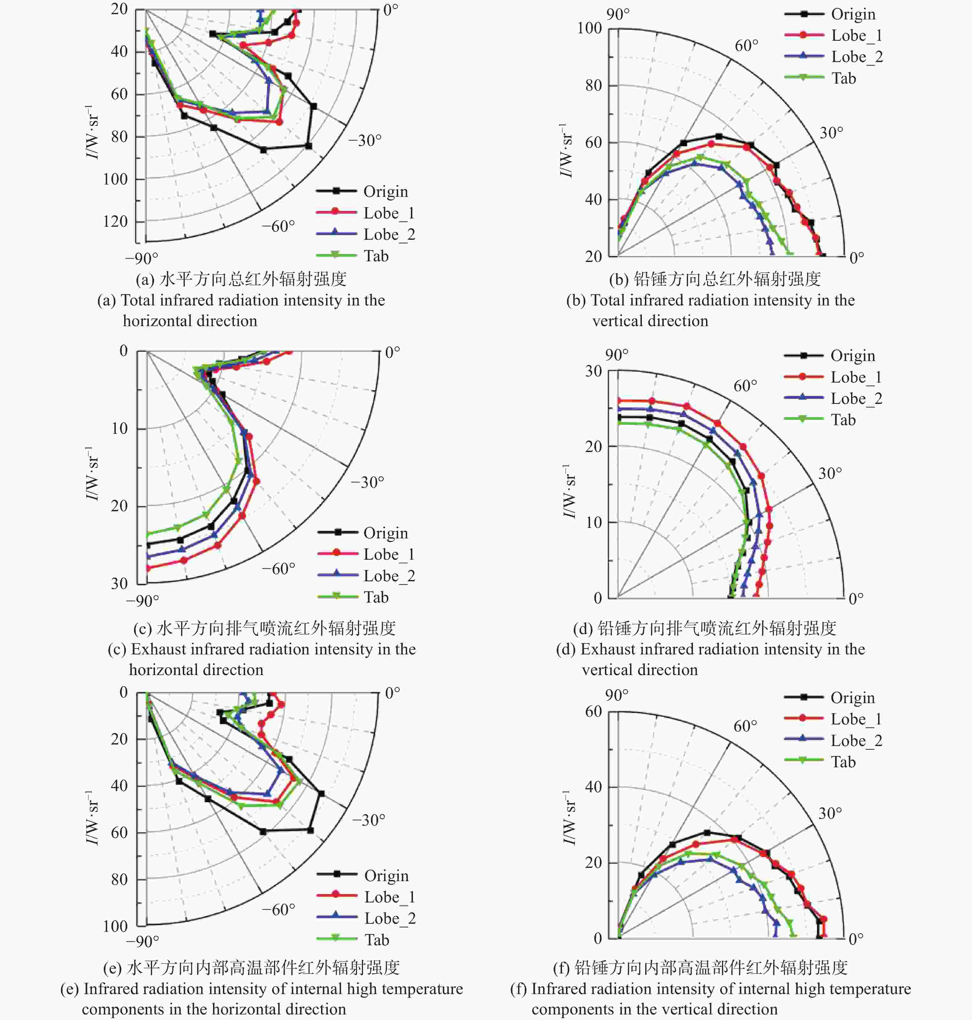
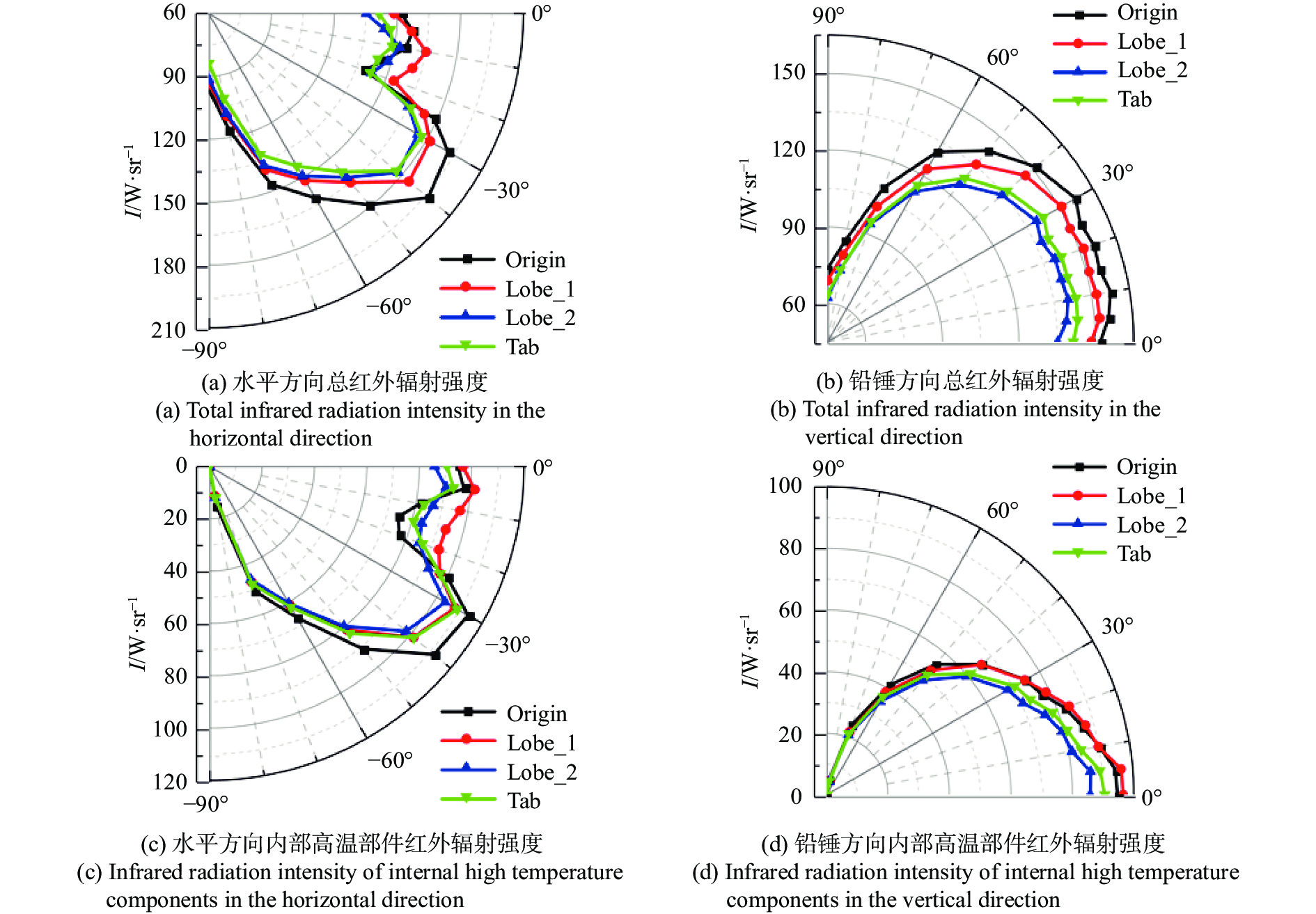
    • 图13显示了水平和铅锤探测面上不同分流喷管出口构型的红外抑制器在3~5 μm波段的红外辐射强度分布。在3~5 μm波段,如遮挡罩和弯曲混合管的内部高温壁面辐射占据了相当大比例的总体红外辐射强度,排气喷流的红外辐射强度也占据了可观的比例,因此另将内部高温壁面的辐射和排气喷流的辐射分解并加以分析,可以清晰地对比不同喷管出口构型对主次流的掺混冷却及对混合管壁面的冷却效果。

      Figure 13.  3-5 μm band infrared radiation intensity distribution

      图13(a)为不同分流喷管出口结构下红外抑制器水平方向的总红外辐射强度,红外辐射强度最大值出现在−40°方向,其中基准模型(Origin)的最大红外辐射强度为120.2 W/sr。在0°~−20°范围内,由于可视的高温排气面积逐渐减小,排气喷流的红外辐射强度逐渐降低,并在−20°位置出现极小值,此探测角度正对红外抑制器的排气出口,可视的排气面积最小,探测到的气体辐射强度最低,如图13(c)所示;内部高温部件的红外辐射强度在−5°位置略微升高,是因为弯曲混合管中后段外侧壁面和蒙皮的可被探测面积变大,之后随着可被探测到的面积逐渐减小,抑制器内部高温部件的红外辐射强度逐渐降低,如图13(e)所示,因此在0°~−20°范围内,红外抑制器水平方向的总红外辐射强度逐渐降低。在−20°~−90°范围内,可视的高温排气面积逐渐增大,排气喷流的红外辐射强度增大,如图13(c)所示;弯曲混合管内侧由于受到高温排气的冲刷而温度更高,随着混合管内侧被探测到,内部高温部件的红外辐射强度迅速升高,之后随着抑制器蒙皮逐渐对遮挡罩和弯曲混合管进行遮挡,内部高温部件的红外辐射强度迅速降低,如图13(e)所示,因此在−20°~−90°范围内,红外抑制器水平方向的总红外辐射强度先升高后降低。

      图13(b)为不同分流喷管出口结构下红外抑制器铅锤方向的总红外辐射强度,红外辐射强度最大值出现在0°方向,其中基准模型(Origin)的最大红外辐射强度为91.9 W/sr。在0°~90°范围内,随着铅锤方向的探测角度增大,可视的高温排气面积变大,当探测角度大于60°,内侧混合管的排气流将不再对其他混合管的排气流造成遮挡,排气喷流的红外辐射强度先升高然后基本保持不变,如图13(d)所示;内部高温部件的红外辐射强度随着抑制器蒙皮逐渐对遮挡罩和弯曲混合管的遮挡逐渐降低,如图13(f)所示,因此在0°~90°范围内,红外抑制器铅锤方向的总红外辐射强度表现为先缓慢降低后迅速降低。

      从降低抑制器总体红外辐射强度的效果来看,不管是在水平探测面上还是铅锤探测面上,Lobe_2模型的总体红外辐射强度整体较低,表现最好,相比基准模型(Origin),在水平探测面上,Lobe_2模型的总体红外辐射强度最大可降低21%,在铅锤探测面上,Lobe_2模型的总体红外辐射强度最大可降低19%,如图13(a)和13(b)。从图13(c)和13(d)可以看出,在降低抑制器排气喷流的红外辐射强度效果上,相比于基准模型(Origin),Lobe_1模型表现较差,Lobe_2模型表现略差,Tab模型表现略好;从图13(e)和13(f)可以看出,Lobe_1模型、Lobe_2模型和Tab模型在降低红外抑制器内部高温部件的红外辐射强度上均有着明显的效果,其中以Lobe_2方案表现最佳,相比基准模型(Origin),在铅锤探测面上,Lobe_2模型的内部高温部件红外辐射强度至少降低19%,最大可降低38%,在水平探测面上,Lobe_2模型的内部高温部件红外辐射强度最大可降低48%。

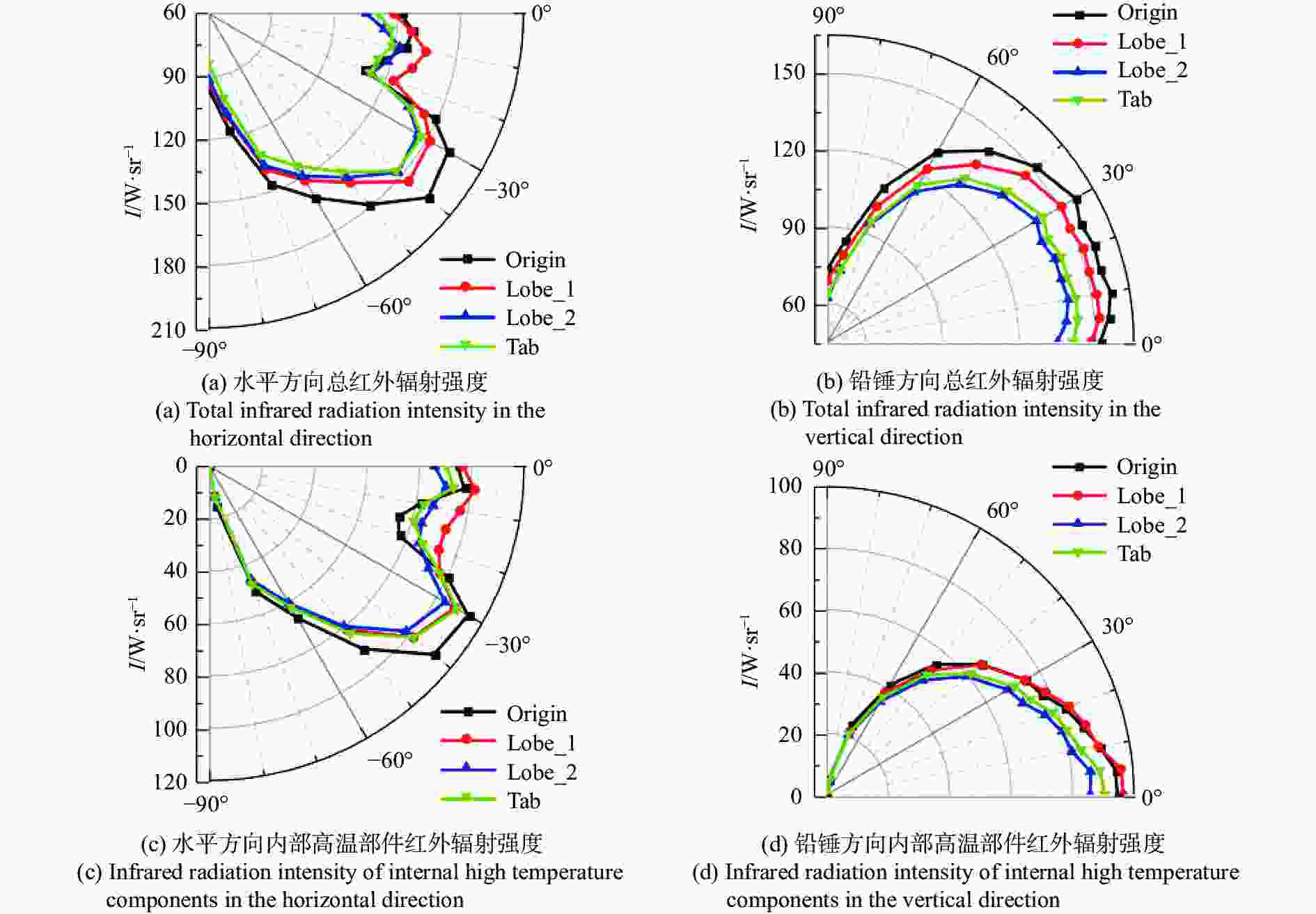
      图14为水平和铅锤探测面上不同分流喷管出口构型的红外抑制器在8~14 μm波段的红外辐射强度分布。在8~14 μm波段,由于高温排气喷流的红外辐射强度占据很小的比例,因此另将内部可视壁面的辐射分解并加以分析,可以清晰地对比不同喷管出口构型对降低红外抑制器在8~14 μm波段红外辐射强度的贡献效果。在水平面,红外辐射强度最大值出现在−40°方向,其中基准模型(Origin)的最大红外辐射强度为196.5 W/sr;在铅锤面,红外辐射强度最大值出现在10°方向,其中基准模型(Origin)的最大红外辐射强度为157.6 W/sr。

      Figure 14.  8-14 μm band infrared radiation intensity distribution

      从降低红外抑制器总体红外辐射强度的效果来看,在水平探测面上,Lobe_1模型由于加热了混合管后段中间壁面区域,贡献了一部分8~14 μm波段的红外辐射强度,在探测角−20°附近,其总体红外辐射强度表现出高于基准模型(Origin),Lobe_2模型和Tab模型在整个探测范围内均表现更好,对红外辐射强度降低的最大比例分别可达11%和13%;在铅锤探测面上,Lobe_1方案、Lobe_2方案和Tab方案在降低抑制器的总体红外辐射强度上有着明显效果,其中Lobe_2方案的效果最佳,相比基准模型(Origin),Lobe_2模型的总体红外辐射强度至少降低10%,最大可降低15%,如图14(a)和14(b)。从图14(c)和14(d)可以看出,水平探测面上,在正对混合管出口方向(−20°)附近,Lobe_1方案在降低抑制器内部高温部件的红外辐射强度上表现最差,从整体来看Lobe_2方案相比基准模型(Origin),其内部高温部件的红外辐射强度最大可降低23%,表现最好;铅锤探测面上,Lobe_1方案对降低抑制器内部高温部件的红外辐射强度没有起到积极作用,在0°~30°范围,其内部高温部件的红外辐射强度高于基准模型(Origin),Lobe_2方案和Tab方案对降低抑制器内部高温部件的红外辐射强度有着明显效果,其中Lobe_2方案的效果最佳,相比基准模型(Origin),Lobe_2模型内部高温部件的红外辐射强度至少降低8%,最大可降低19%。

    • 文中进行了基准分流喷管和两种带波瓣出口的分流喷管引射式红外抑制器缩比实验和全尺寸数值仿真研究,在实验验证的基础上,针对红外抑制器的引射系数、总压恢复系数、混合管的出口和壁面温度分布、红外辐射强度,在文中研究参数范围内得到如下结论:

      1)分流喷管带有一定外扩张角的常规波瓣出口结构会造成高温主流过早触附混合管壁面,红外抑制器的引射系数和总压恢复系数都降低;外扩张角为0的特殊波瓣出口结构,可以让主流在混合管内充分发展,红外抑制器的引射系数增大3.8%,总压恢复系数相比采用常规波瓣出口结构基本不变;带突片的分流喷管出口结构引射能力最强,红外抑制器的引射系数增大10.6%,但总压恢复系数下降明显,这是因为突片结构深入主流,对其流动有阻碍。

      2)相对于基准分流喷管,带波瓣出口的分流喷管结构能有效降低混合管出口排气最高温度,Lobe_1模型的中间混合管出口排气最高温度降低到680.2 K,降低了65.1 K,Lobe_2模型的中间混合管出口排气最高温度降低到682.5 K,降低了62.8 K;带突片出口的分流喷管结构能有效降低混合管的出口排气平均温度,Tab模型的内侧混合管出口排气平均温度降低到595.0 K,降低了19.3 K,但在降低中间混合管出口排气高温区温度上效果较差。

      3) Lobe_2方案在降低混合管壁面温度上效果最佳;Lobe_1方案虽降低了混合管上下方区域的壁面温度,但造成混合管中后段外侧区域的壁面温度升高;Tab方案在降低混合管壁面温度上效果较差。

      4)在3~5 μm波段,Lobe_2模型降低总体红外辐射强度效果最好,水平方向最大可降低21%;铅锤方向最大可降低19%。在8~14 μm波段,水平方向上,Lobe_2模型和Tab模型降低总体红外辐射强度效果接近,最大降低分别为11%和13%;铅锤方向上,Lobe_2模型红外抑制效果最佳,总体红外辐射强度至少降低10%,最大可降低15%。

Reference (22)

Catalog

    /

    DownLoad:  Full-Size Img  PowerPoint
    Return
    Return