Volume 53 Issue 4
Apr.  2024
Turn off MathJax
Article Contents

Li Bin, Gao Sisi, Wang Haichao, Chen Jiayi, Chen Xi, Lu Yuting. Adjustment and testing method of large aperture mirror Bipod support structure[J]. Infrared and Laser Engineering, 2024, 53(4): 20230657. doi: 10.3788/IRLA20230657
Citation: Li Bin, Gao Sisi, Wang Haichao, Chen Jiayi, Chen Xi, Lu Yuting. Adjustment and testing method of large aperture mirror Bipod support structure[J]. Infrared and Laser Engineering, 2024, 53(4): 20230657. doi: 10.3788/IRLA20230657

Adjustment and testing method of large aperture mirror Bipod support structure

doi: 10.3788/IRLA20230657
Funds:  National Key Research and Development Program of China (2022YFB3403800)
  • Received Date: 2023-11-22
  • Rev Recd Date: 2023-12-25
  • Publish Date: 2024-04-25
  •   Objective  In order to effectively deal with the interference of gravity error in the installation and adjustment of large aperture remote sensing camera on the surface, the installation and adjustment mode of large aperture remote sensing camera is gradually changed from the horizontal form of optical axis to the vertical form of optical axis. Correspondingly, the support structure and assembly requirements of the main mirror of the camera are also constantly innovated. In order to meet the needs of mirror support and weight reduction, the Bipod structure is a more common structural form in the form of mirror support of 1 m and above caliber. Different from the traditional frame support form, it has a great change in the optical and mechanical structure bonding and structural position calibration needs. In order to ensure that the assembly positioning accuracy and surface shape change of the mirror under the Bipod support structure meet the requirements of the system index, a high-precision assembly method for the Bipod support structure is proposed.  Methods  In this paper, a method of assembly and adjustment of large-aperture mirror is proposed, which combines multi-objective spatial position conversion and Stewart structure motion inversion. This method can effectively ensure the accuracy of the optical and mechanical structure adhesion points, and realize the high-precision six-dimensional adjustment between the mirror and the main bearing plate only by relying on the mirror's own support structure. By decomposing the error index of the optical system of the remote sensing camera, the requirements of the reflector installation index are determined (Fig.4). Then the laser tracker was used to measure and construct the spatial coordinate system of the mirror and the support pad. The coordinate system restoration principle based on the nominal point was adopted to achieve the normalization of the coordinate system. According to the measured data of the nominal point on the support pad, the position of the support pad was corrected and fixed (Fig.8). Finally, based on the characteristics of the Bipod structure itself, the relationship between the length of the Bipod rod and the position of the mirror is calculated (Eq.14), and the position adjustment between the mirror and the main structure of the camera is realized by adjusting the length of the adjusting rod.  Results and Discussions  The bottom-up error distribution method was adopted to sort out the tolerance of various error sources in the process of optical system installation. Error distribution follows a top-down order, with the sum of the squares of the error coefficients at the lower level equal to the square of the error at the higher level. Finally, the wave aberration RMS caused by the main mirror assembly is 0.025λ, including the influence of the position deviation and surface shape change of the main mirror assembly. The laser tracker was used to measure and locate the position of the support pad and the mirror, and the assembly of the mirror and the support pad was completed. The surface shape variation (RMS) before and after the installation was 0.008λ (Fig.9), which met the requirements of the installation error index. A laser tracker was used to measure the position deviation between the mirror and the bearing plate, and the adjusting length of the Bipod rod was calculated using the Stewart structure motion inversion algorithm. After the final debugging, the setting position error of the mirror was 0.004 1 mm, which met the setting error index requirements.  Conclusions  Based on the setting process of a large aperture reflective remote sensing camera with Bipod structure, the setting error interval of the main mirror in the system is analyzed, and the shape error RMS value of the mirror assembly after setting is determined not to exceed 0.025λ. Based on this standard, the positioning, bonding, adjustment and detection scheme of the mirror Bipod structure is formulated. The practical results show that the method can effectively control the assembly positioning accuracy and surface shape error of the mirror, the positioning accuracy of the support pad can reach 0.029 mm, and the position adjustment accuracy of the mirror and the bearing plate can reach 0.041 mm. The installation results can meet the system imaging requirements of large aperture remote sensing cameras.
  • [1] 岳丽清, 张继友. 三线阵相机视轴夹角及线阵平行性装调测试 [J]. 航天返回与遥感, 2012, 33(3): 35-40.

    Yue Liqing, Zhang Jiyou. Alignment method of axis angle and linear array parallelism for three-line array mapping camera [J]. Spacecraft Recovery and Remote Sensing, 2012, 33(3): 35-40. (in Chinese)
    [2] 明名, 王建立, 张景旭等. 大口径望远镜光学系统的误差分配与分析 [J]. 光学精密工程, 2009, 17(1): 104-108. doi:  10.3321/j.issn:1004-924X.2009.01.017

    Ming M, Wang J L, Zhang J X, et al. Error budget and analysis for optical system in large tele-scope [J]. Optics and Precision Engineering, 2009, 17(1): 104-108. (in Chinese) doi:  10.3321/j.issn:1004-924X.2009.01.017
    [3] 李斌, 陈佳夷, 王海超等. 面型误差和失调量对同轴三反系统像质的影响 [J]. 红外与激光工程, 2018, 47(9): 0918002.

    Li Bin, Chen Jiayi, Wang Haichao, et al. The effect of surface error and alignment aberration on the imaging quality of the coaxial three mirror system [J]. Infrared and Laser Engineering, 2018, 47(9): 0918002. (in Chinese)
    [4] 巩盾, 田铁印, 王红. 利用Zernike系数对离轴三反射系统进行计算机辅助装调 [J]. 光学精密工程, 2010, 18(8): 1754-1758.

    Gong Dun, Tian Tieyin, Wang Hong. Computer-aided alignment of off-axis three-mirror system by using Zernike coefficients [J]. Optics and Precision Engineering, 2010, 18(8): 1754-1758. (in Chinese)
    [5] Pang Zhihai, Fan Xuewu, Ma Zhen, et al. The computer aided alignment study of three-mirror off-axis field bias optical system [C]//SPIE, 2012, 8417: 1-5.
    [6] Zhou Shuang, Liu Zijian. The assembly error analysis of optical system and path optimization of alignment [J]. Machinery Design & Manufacture, 2022, 37(1): 159-167. (in Chinese)
    [7] Chen Jiayi, Wang Haichao, Huo Tengfei, et al. Assembly for Φ1.3 m aperture telescope [J]. Optical Technique, 2021, 47(1): 12-16. (in Chinese)
    [8] 杨立保, 李艳红, 王晶等. 光电跟踪系统Φ1000 mm主镜的装调 [J]. 光学精密工程, 2018, 26(7): 1633-1641. doi:  10.3788/OPE.20182607.1633

    Yang Libao, Li Yanhong, Wang Jing, et al. Photoelectric tracking system Φ 1000 mm main mirror adjustment [J]. Optics and Precision Engineering, 2018, 26(7): 1633-1641. (in Chinese) doi:  10.3788/OPE.20182607.1633
    [9] 陈佳夷, 王聪, 霍腾飞等. 激光跟踪仪检测大口径非球面方法研究 [J]. 应用光学, 2021, 42(2): 299-303.

    Chen Jiayi, Wang Cong, Huo Tengfei, et al. Research on detection method of large-aperture aspheric surface by laser tracker[J]. Journal of Applied Optics, 2021, 42(2):299-303.
    [10] Zhao Fei , Cui Xia, Yuan Guangwei. Iterative acceleration methods with second-order time accuracy for nonlinear diffusion equations [J]. Advances in Computational Mathematics, 2020, 46(4):34-40.
    [11] 陈佳夷, 王海超, 李斌, 等. Bipod支撑大口径反射镜的零重力面形测试技术 [J]. 红外与激光工程, 2022, 51(5): 20210496.

    Chen jiayi, Wang Haichao, Li Bin, et al. 0 g surface figure test of large aperture mirror supported by Bipod [J]. Infrared and Laser Engineering, 2022, 51(5): 20210496. (in Chinese)
    [12] 周于鸣, 杨秋实, 孟晓辉等. 大口径光学组件重力翻转测试方法验证及应用 [J]. 航天返回与遥感, 2019, 40(3): 33-39.

    Zhou Yuming, Yang Qiushi, Meng Xiaohui, et al. Verification and application of gravity flip test method for large aperture optical components [J]. Spacecraft Recovery & Remote Sensing, 2019, 40(3): 33-39. (in Chinese)
    [13] 杨维帆, 曹小涛, 张彬等. 空间望远镜次镜六自由度调整机构精密控制 [J]. 红外与激光工程, 2018, 47(7): 0718007.

    Yang Weifan, Cao Xiaotao, Zhang Bin, et al. Six degree of freedom precision control for space camera secondary mirror adjusting mechanism [J]. Infrared and Laser Engineering, 2018, 47(7): 0718007. (in Chinese)
  • 加载中
通讯作者: 陈斌, bchen63@163.com
  • 1. 

    沈阳化工大学材料科学与工程学院 沈阳 110142

  1. 本站搜索
  2. 百度学术搜索
  3. 万方数据库搜索
  4. CNKI搜索

Figures(15)  / Tables(2)

Article Metrics

Article views(12) PDF downloads(5) Cited by()

Related
Proportional views

Adjustment and testing method of large aperture mirror Bipod support structure

doi: 10.3788/IRLA20230657
  • 1. Beijing Institute of Space Mechanics & Electricity, Beijing 100086, China
  • 2. Beijing Institute of Spacecraft System Engineering Laboratory, Beijing 100094, China
Fund Project:  National Key Research and Development Program of China (2022YFB3403800)

Abstract:   Objective  In order to effectively deal with the interference of gravity error in the installation and adjustment of large aperture remote sensing camera on the surface, the installation and adjustment mode of large aperture remote sensing camera is gradually changed from the horizontal form of optical axis to the vertical form of optical axis. Correspondingly, the support structure and assembly requirements of the main mirror of the camera are also constantly innovated. In order to meet the needs of mirror support and weight reduction, the Bipod structure is a more common structural form in the form of mirror support of 1 m and above caliber. Different from the traditional frame support form, it has a great change in the optical and mechanical structure bonding and structural position calibration needs. In order to ensure that the assembly positioning accuracy and surface shape change of the mirror under the Bipod support structure meet the requirements of the system index, a high-precision assembly method for the Bipod support structure is proposed.  Methods  In this paper, a method of assembly and adjustment of large-aperture mirror is proposed, which combines multi-objective spatial position conversion and Stewart structure motion inversion. This method can effectively ensure the accuracy of the optical and mechanical structure adhesion points, and realize the high-precision six-dimensional adjustment between the mirror and the main bearing plate only by relying on the mirror's own support structure. By decomposing the error index of the optical system of the remote sensing camera, the requirements of the reflector installation index are determined (Fig.4). Then the laser tracker was used to measure and construct the spatial coordinate system of the mirror and the support pad. The coordinate system restoration principle based on the nominal point was adopted to achieve the normalization of the coordinate system. According to the measured data of the nominal point on the support pad, the position of the support pad was corrected and fixed (Fig.8). Finally, based on the characteristics of the Bipod structure itself, the relationship between the length of the Bipod rod and the position of the mirror is calculated (Eq.14), and the position adjustment between the mirror and the main structure of the camera is realized by adjusting the length of the adjusting rod.  Results and Discussions  The bottom-up error distribution method was adopted to sort out the tolerance of various error sources in the process of optical system installation. Error distribution follows a top-down order, with the sum of the squares of the error coefficients at the lower level equal to the square of the error at the higher level. Finally, the wave aberration RMS caused by the main mirror assembly is 0.025λ, including the influence of the position deviation and surface shape change of the main mirror assembly. The laser tracker was used to measure and locate the position of the support pad and the mirror, and the assembly of the mirror and the support pad was completed. The surface shape variation (RMS) before and after the installation was 0.008λ (Fig.9), which met the requirements of the installation error index. A laser tracker was used to measure the position deviation between the mirror and the bearing plate, and the adjusting length of the Bipod rod was calculated using the Stewart structure motion inversion algorithm. After the final debugging, the setting position error of the mirror was 0.004 1 mm, which met the setting error index requirements.  Conclusions  Based on the setting process of a large aperture reflective remote sensing camera with Bipod structure, the setting error interval of the main mirror in the system is analyzed, and the shape error RMS value of the mirror assembly after setting is determined not to exceed 0.025λ. Based on this standard, the positioning, bonding, adjustment and detection scheme of the mirror Bipod structure is formulated. The practical results show that the method can effectively control the assembly positioning accuracy and surface shape error of the mirror, the positioning accuracy of the support pad can reach 0.029 mm, and the position adjustment accuracy of the mirror and the bearing plate can reach 0.041 mm. The installation results can meet the system imaging requirements of large aperture remote sensing cameras.

    • 遥感卫星的对地观测能力取决于卫星平台上搭载的空间遥感相机,在卫星运行轨道高度不变的情况下,遥感相机的口径越大,其分辨率就越高。为满足空间遥感相机的高分辨率要求,提升遥感相机的口径是必经之路,而大口径的主反射镜组件作为相机的核心部件,其支撑方式为适应大重量、大尺寸的反射镜,也发生了巨大变化。在1 m及以上口径的反射镜支撑结构中,为排除重力变形对反射镜面形的影响,通常不再采用镜框的形式,转而在反射镜背部或侧面设置离散支撑点以实现光机连接与反射镜支撑。这类离散支撑的结构形式可以分为主动支撑和被动支撑两大类型,主动支撑由于其灵活性和可调节性,常被应用于一些轻量化高、稳定性差的光学元件支撑,通过在轨调节确保反射镜面形精度;相对于主动支撑,被动支撑方式则是使用单纯的结构来实现大口径、高精度要求光学元件的稳定支撑的,是现阶段主要的大口径光学元件支撑方式,Bipod结构就是其中最具代表性的支撑结构,在大口径遥感相机领域应用广泛,如美国的GeoEye、Word-View、Kepler等遥感相机的主反射镜均采用了这一结构形式。

      Bipod支撑结构的装配与传统框式支撑结构有着巨大的差别,也存在着诸多装调与检测难点。首先光机连接点位处于无约束状态,需要精准测量并定位全部支撑垫的位置并使用胶接剂粘接,才能确保支撑应力均匀以及后续支撑结构的顺利安装。此外,由于Bipod支撑结构在完成装调前,是处于分离状态的六根长度可调的支撑杆,装配完成后需确保反射镜与相机主承力板之间的相对位置处于一个较高精度状态,该精度将直接决定相机光轴的指向精度[1]。最后,在反射镜组件的面形检测环节中还需排除掉反射镜在Bipod支撑结构下的重力影响,才能预测相机进入运行轨道后的反射镜面形误差,保证相机的在轨成像质量。

      为解决大口径反射镜组件装调过程的诸多难题,确保反射镜组件的装配精度与面形误差满足指标要求,文中提出了一种基于空间位置转换和并联六自由度调整的大口径反射镜组件装调方法,可有效解决离散点位定位和反射镜整体姿态控制问题,并在北京三号B遥感卫星的光学载荷装调过程中进行了应用验证。

    • 空间遥感相机的两大核心指标要求包括相机的光学传递函数与稳定性,其中光学传递函数反应了相机的成像清晰度,稳定性则是确保相机能够顺利通过火箭发射阶段进入运行轨道的保证。作为相机核心部组件的大口径主反射镜,在其装调过程中由装配指标导致的反射镜面形误差、光轴指向精度以及组件的抗振动性能都与相机的总体指标息息相关。

      以常见同轴三反式光学系统为例,图1分析了主反射镜组件的装配指标要求,相机光学系统的核心光学元件包括主镜、次镜、三镜和折转镜,其中折转镜不参与成像,仅起到折转光路的作用。

      Figure 1.  Optical path diagram of remote sensing camera optical system

      相机光学系统的截止频率为:

      式中:F0为截止频率;F为系统焦距;D为有效口径;λ为系统的检测波长。F/D=10,λ=632.8 nm。

      以光学系统波像差的2倍衍射极限为系统装调目标,从光学系统的传递函数曲线中(见图2)取截止频率的中心值f=79 lp/mm作为相机光学系统传函的评判点,在排除系统中各反射镜的面形误差和失调量误差影响后,在该空间频率下系中心视场的光学系统调制传递函数(Modulation Transfer Function, MTF)为0.33,该传函数值即为系统的理论设计值。

      Figure 2.  Camera optical system transfer function curve

      根据遥感相机光学镜头装调过程中装调因子η的要求,可反向推导得到主反射镜的面形误差ε变化区间以及失调量调校精度,并据此控制主镜组件装配过程中的光机连接点定位精度和胶接一致性。其中,相机光学系统的装调因子是由装调前后相机光学传函的数值比得到:

      式中:η为装调因子;MTF*为装调后系统传函;MTF为系统设计传函。

      相机的装调因子代表相机装调结果与理论设计值之间的偏差,通常遥感相机光学系统装调因子的设计指标要求在0.85~0.95之间,为便于过程分析装调因子η取平均值0.9。根据相机镜头装调因子要求,系统传函指标在镜头制造过程中因装调产生的反射镜面形误差与失调量导致的传函损失值约为0.033,由光学元件加工导致的面形误差和几何参数(顶点曲率半径和非球面系数)偏差,对于传函的影响值为0.028,因此最终光学系统装调完成后的目标传递函数值约为0.27,对应的光学系统各视场平均波像差RMS为0.076λ

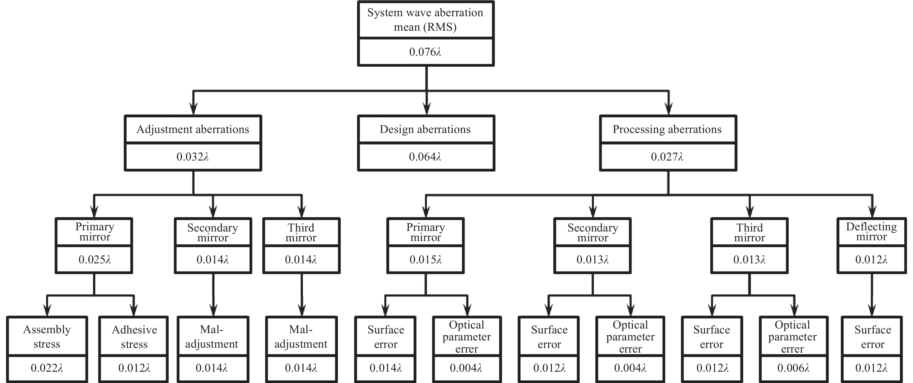
      根据光学系统的最终装调目标,使用CODE-V光学设计软件分析光学系统中各个零部件的加工残留误差和装调误差,采用Bottom-Up 误差分配方式[2],梳理光学系统装调过程中各项误差源的允差,如图3所示。误差分配遵循自上而下的顺序,下级误差系数的平方和等于上级误差的平方。最终得到由主镜组件装调导致的波像差RMS为0.025λ,其中包括主镜装调的位置偏差和面形变化影响[3]

      由于主镜是整个光学系统的装调位置基准,在光学系统失调量调校阶段[4-5],不对主镜进行位置调整,只能在主镜组件装调过程中控制主镜相对于承力板位置,控制光学系统的焦平面位置[6]。此外,主镜支撑垫的定位准确度与Bipod杆的长度一致性也会直接影响主镜的面形。

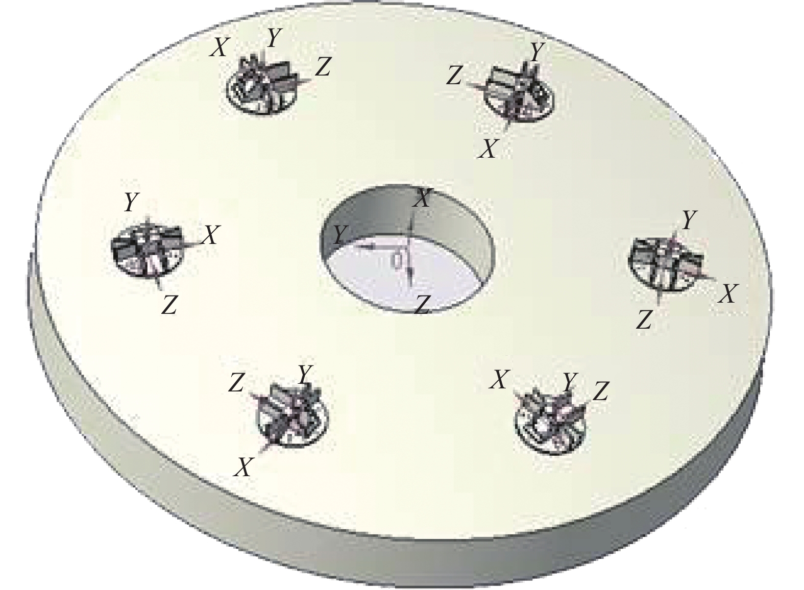
      主镜组件的结构形式如图4所示,其中圆柱形刚体为反射镜,具备一定斜角的六杆支撑结构就是Bipod结构。

      Figure 3.  Error allocation of remote sensing camera optical system

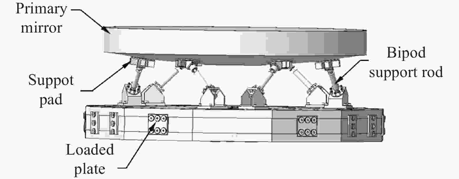
      Figure 4.  Typical reflector Bipod support structure schematic

      Bipod支撑结构的主反射镜组件装调需要分两个阶段进行,从图4中可以清楚看到,反射镜组件主要由反射镜、支撑垫、Bipod杆和承力板几个部分组成。反射镜装调的第一阶段需先将反射镜与支撑垫进行定位、装配,期间需准确定位六个支撑垫与反射镜之间的相对位置。由于整个装调过程为串行过程,所以在支撑垫的定位阶段,除了需准确控制支撑垫与反射镜之间的平移位置外,还需依据后续Bipod杆的安装角度,定位支撑垫的朝向角度,即支撑垫相对于反射镜的六个维度均需精确控制。第二阶段的主要工作是将粘接好支撑垫的反射镜与Bipod杆、承力板进行定位与连接,这一过程决定了反射镜的光轴指向与平移位置[7]

    • 支撑垫需定位、安装在主反射镜背部,反射镜背面为弧面,且无结构限位,如图5所示。当支撑垫相对反射镜的装配位置与理论位置间存在偏差时,将会引入额外的装配应力,进而导致反射镜面形精度下降[8]

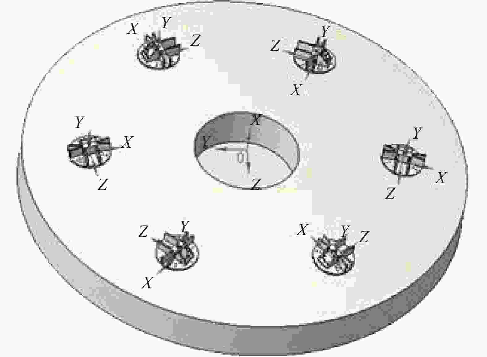
      Figure 5.  Assembly relationship between main mirror and support pad

      根据上文的系统误差分配结果,主反射镜由装配导致的面形误差需控制在RMS0.012λ以下。建立主反射镜的有限元模型并对其进行力学仿真分析,如图6所示,得出支撑垫的装配位置偏差为0.05 mm时,会导致主镜面形变化RMS0.012λ,据此可得到支撑垫的装配精度需控制在±0.05 mm内。

      Figure 6.  Finite element model of the main mirror

      为准确定位六个支撑垫在主反射镜坐标系下的空间位置,需先建立主镜的基准坐标系,坐标系以主镜的上端面为XOY面,外圆柱中心轴线与上端面的交点为坐标原点OZ轴为过原点的端面法线,再选定一个主镜特征点作为Y轴的轴上点,即可构建主镜基准坐标系M0[9]

      使用三坐标仪依次测量六个支撑垫的结构特征,并据此建立其对应的坐标系Ni(i=1~6)。在每个支撑垫上安装三个靶球座,用于放置激光跟踪仪靶球(见图7)。测量并记录支撑垫坐标系下靶球的球心坐标。

      Figure 7.  Structural characteristics of primary mirror reference coordinate system

      根据主镜结构设计模型,可以确定六个支撑垫坐标系与主镜坐标系之间的转换关系,即:

      式中:Ti为各个支撑垫坐标系与主镜坐标系之间的变换矩阵,矩阵包含空间六维变量,即三个旋转角度αβγ和三个平移量dx、dy、dz,表述形式如下:

      依据机械加工精度保证,在支撑垫坐标系下,各个支撑垫上的三个靶球座中心点坐标偏差可以控制在0.002 mm以内,表述为$ {P}\{{a}\left({{x}}^{{a}},{{y}}^{{a}},{{z}}^{{a}}\right),{b}\left({{x}}^{{b}},{{y}}^{{b}},{{z}}^{{b}}\right), {c}\left({{x}}^{{c}},{{y}}^{{c}},{{z}}^{{c}}\right)\} $,故可计算得出在全部支撑垫点位在主镜坐标系下的坐标$ {{{P}}_{{i}}\{{a}}_{{i}}\left({{x}}_{{i}}^{{a}},{{y}}_{{i}}^{{a}},{{z}}_{{i}}^{{a}}\right),{{b}}_{{i}}\left({{x}}_{{i}}^{{b}},{{y}}_{{i}}^{{b}},{{z}}_{{i}}^{{b}}\right),{{c}}_{{i}}\left({{x}}_{{i}}^{{c}},{{y}}_{{i}}^{{c}},{{z}}_{{i}}^{{c}}\right)\} $,则:

      将支撑垫置于主镜背面理论安装位置附近,使用激光跟踪仪测量主镜结构基准并建立主镜坐标系,在主镜坐标系下测量支撑垫上三个固定点位的坐标,得到:

      根据实测点坐标与理论点坐标,可以得出支撑垫当前位置与理论位置之间的转换关系为:

      其中,

      采用Newton迭代法[10]解上述方程式,求得被测支撑垫所需调节的角度$({{\mathrm{\alpha }}_{{i}}}^{'},{{\mathrm{\beta }}_{{i}}}^{'},{{\mathrm{\gamma }}_{{i}}}^{'})$和平移量$ ({{{\mathrm{d}}x}_{i}}{'}, {{{\mathrm{d}}y}_{i}}{'},{{{\mathrm{d}}z}_{i}}{'}) $,根据解算结果,使用调整工装将全部支撑垫调节到位并注胶固化,即完成主反射镜与支撑垫的装配工序。

    • Φ1.3 m反射镜组件的装调过程中,采用上述方法定位支撑垫相对于反射镜的位置,并按照以下流程完成反射镜的装调。

      1) 在反射镜结构上固定不少于六个跟踪仪靶球座,作为反射镜坐标系的标称点位。

      2) 使用激光跟踪仪测量反射镜端面与外圆柱(见图7),建立反射镜的结构基准坐标系,测量并记录基准坐标系下反射镜各个标称点的坐标;

      3) 翻转反射镜,使用跟踪仪测量标称点,恢复其结构基准坐标系;

      4) 将支撑垫按照结构设计布局置于反射镜背部,粗略调节支撑垫的角度与位置;

      5) 使用跟踪仪实时监测支撑垫上三个靶球(见图8)的坐标,按照公式(7)解算支撑垫的位置偏差并据此调节支撑垫位置,使靶球坐标与结构设计坐标基本重合;

      Figure 8.  Installation diagram of the target ball seat of the support pad

      6) 在支撑垫与反射镜的间隙中注入光机结构粘接剂,静置固化。
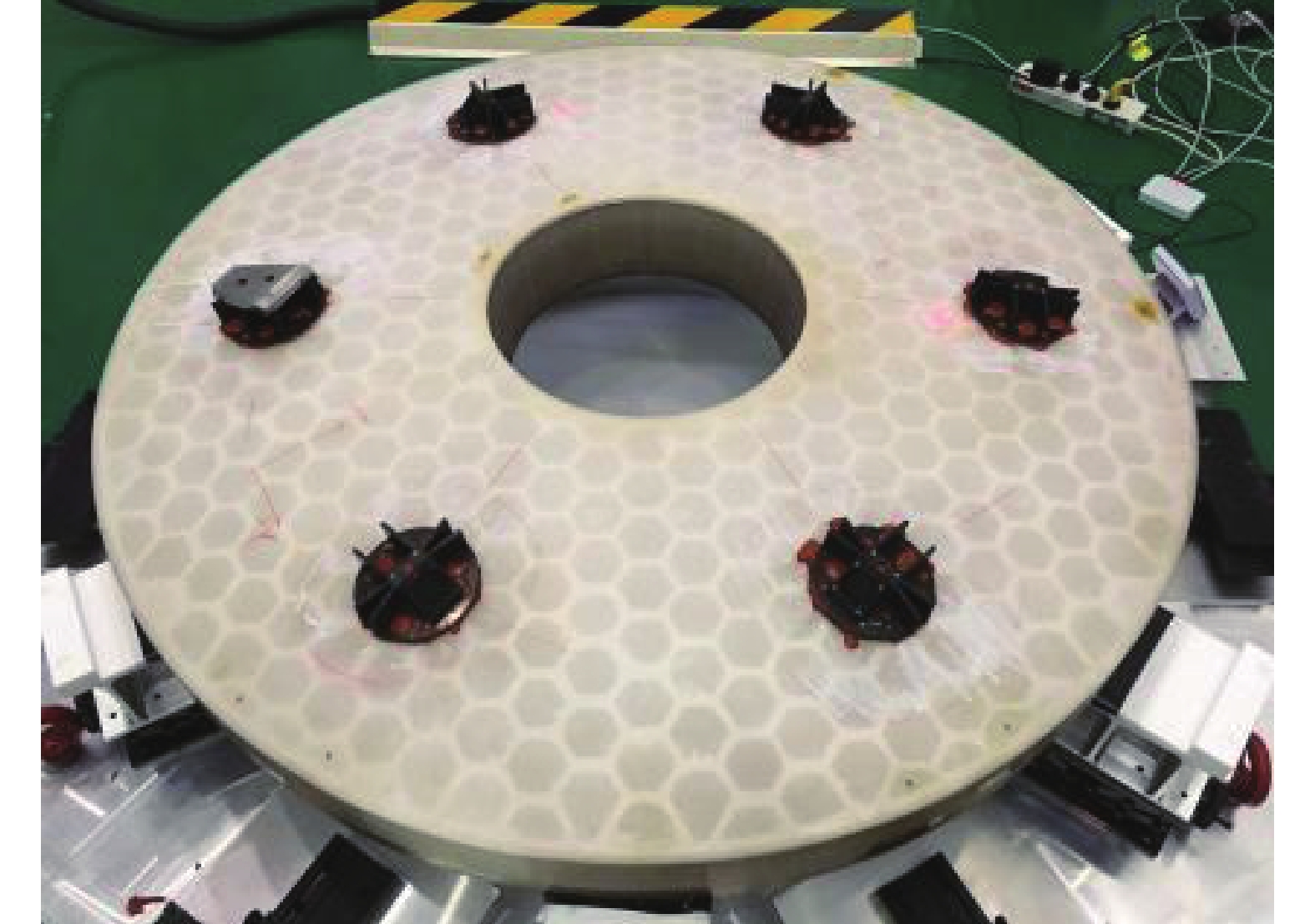
      装调完成的反射镜与支撑垫如图9所示。

      Figure 9.  Mirror and support pad installation and adjustment effect

      装配过程中涉及的误差因子主要包括:1)支撑垫上靶球座安装孔的位置加工误差δ2=0.002 mm(支撑垫采用数控机床加工成型,加工后需通过三坐标仪进行公差检测);2)激光跟踪仪的仪器测量误差为15 μm+6 μm/m,装配过程中的测量距离在2 m内,故测试误差为δ3=0.027 mm;3)支撑垫调整工装的调节误差为δ4=0.01 mm,综合计算得到整个主镜与支撑垫装配过程误差为:

      装配误差δ<±0.05 mm,满足指标要求,可保证主镜应装配变形导致的面形变化符合要求。

      对照反射镜装调前后的面形,装调前反射镜面形误差仅由加工残留误差和重力误差组成,装调后反射镜面形误差包含加工残留误差、重力形变误差以及装配误差。剔除由重力形变所导致面形误差[11-12]的影响,测试结果如图10所示,反射镜安装支撑垫之前的面形均方根值为0.014λ@632.8 nm,完成支撑垫安装后的面形均方根值为0.016λ@632.8 nm,装调前后的面形变化量为0.008λ,符合设计指标要求。

      Figure 10.  (a) The front shape error of mirror assembly and adjustment; (b) Mirror configuration error; (c) Variation of surface shape before and after installation

    • 完成主镜与支撑垫的定位粘接后,还需将主镜通过Bipod支撑结构与承力板装配为一体状态。在该装配过程中主要需控制主镜相对于承力板之间的平移和倾斜,同时还需顾及六根Bipod杆长度的一致性。主镜作为整个光学系统的装调基准,主镜与承力板之间的位置偏差除了会导致基准的偏离外,还会导致Bipod杆与胶杯之间间隙的不一致。其中,主镜基准位置的偏移,可通过后续次镜与三镜的位置调节进行补偿,不会引入额外的像差。但是,由于折转镜是先于主镜前完成装调的,主镜轴向平移对于光学系统后截距的影响无法补偿,会影响后续焦面的安装位置。同时,Bipod杆与胶杯之间间隙的不一致,在后续的结构粘接过程中会引入额外的装配应力,导致反射镜面形发生变化。综合分析,将主镜的装配位置偏差控制在±0.1 mm,不仅可有效保障主镜装调后面形误差RMS小于0.022λ,还能确保系统后截距的准确度。

      Bipod结构是由六根等长支撑杆以不同倾斜角度实现对反射镜的稳定支撑,结构形式见图1。Bipod杆通过两端的球头与上下结构的球窝连接在一起,如图11所示,该结构具备在重力场下的静定支撑特性,仅依靠反射镜的自重即可保证Bipod杆各向受力一致[13]。鉴于结构的这一特性,在进行Bipod支撑结构装配与调试过程中,先将主镜、Bipod结构和承力板组装为一体,Bipod杆处于自由可调节状态,通过旋转调节顶丝可控制六根Bipod杆的长度。

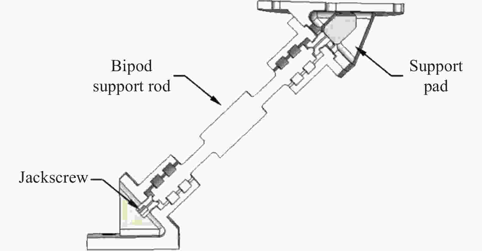
      Figure 11.  Partial diagram of Bipod support structure

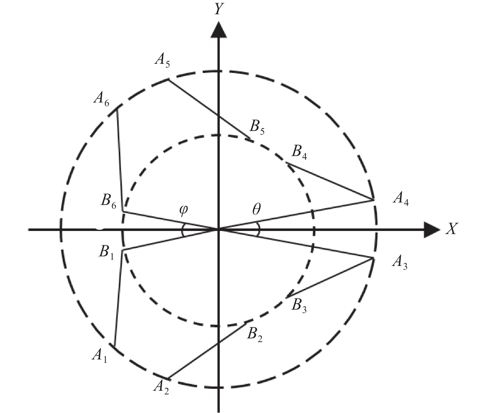
      使用激光跟踪仪测量主镜结构基准(见图7),并建立主镜坐标系{M0}(Om-XYZ),将建立好的主镜坐标系沿Z轴向下平移D1(D1为主镜上端面距离支撑垫平面的距离),得到支撑垫平面坐标系{B0}(Ob-XYZ);同时测量承力板结构基准,建力承力板坐标系{A0}(Oa-XYZ)。以承力板坐标系A0为参考坐标系,支撑垫平面坐标系B0为运动坐标系,主镜组件的运动模型可简化为图12所示。图中Aii=1~6)为Bipod杆与参考坐标系XOaY平面的交点,Bii=1~6)为Bipod杆与运动坐标系XObY平面的交点。Bipod支撑结构调整的最终状态是使动态坐标系与静态坐标系处于重合状态(除Z轴平移外),两个坐标系在Z轴上的平移偏差为D2

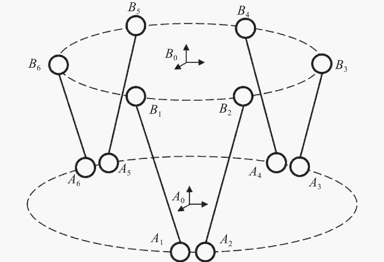
      Figure 12.  Schematic diagram of Bipod support structure model of primary mirror component

      其中,各个点位之间的向量关系均符合:

      Bipod支撑结构各点位分布的俯视图如图13所示,运动坐标系与参考坐标系不存在的旋转偏差,其中X轴过A3A4B1B6的中心点。

      Figure 13.  Top view of Bipod support structure support point

      通过计算可以得出,Bipod结构上平面支撑点位B1~B6在运动坐标系下的坐标为:

      同理,Bipod结构下平面支撑点位A1~A6在参考坐标系下的坐标为:

      上述式中的$ a=\mathrm{\varphi }/2,b=\theta /2 $,分别指代动态坐标系与静态坐标系中支撑点、原点向量与X轴的夹角;r代表上平台支撑点拟合圆的半径,R代表下平台支撑垫拟合圆的半径。所有支撑点在其所处平面坐标系下的坐标为已知状态,因此向量$ \overline{O_b B_i}$、$ \overrightarrow{O_a A_i}$均为已知。

      动态坐标系B0A0之间存在一个变换矩阵T0T0包含了坐标系B0相对于A0的角度(α,β,γ)和平移量(dx,dy,dz)偏差,偏差数值通过激光跟踪仪可以测量得出,变换矩阵表述为:

      ObB1~B6均通过转换运算,转换至参考坐标系A0下,则:

      得到上平面支撑点在参考坐标系下的坐标Ob′和B1′~B6′,代入公式(9)可得:

      求解上述方程组,可以得出六根Bipod杆当前状态下杆长${l}_{i}(i=1,\cdots, 6)$,减去理论状态下的杆长$ {l}_{0} $,即可得到各杆所需调节的长度为:

      依据计算所得的调整结果,调节Bipod杆下端调节顶丝,最终使得主镜与承力板的相对位置满足设计要求,注胶并固化,即可完成主镜组件装调。

    • 在开展反射镜与承力板装调工作前,需先建立承力板坐标系,如图14所示。使用激光跟踪仪测量承力板上外圆结构装配点位并拟合出特征圆周,测量前镜身安装平面并拟合出特征平面,据此建立承力板坐标系,测量并记录坐标系下的标称点坐标值。

      Figure 14.  Construction diagram of bearing plate coordinate system

      按照图1所示,完成反射镜、Bipod支撑杆和承力板的装配,使用激光跟踪仪测量承力板与反射镜上的标称点,分别恢复承力板和反射镜的坐标系,以承力板坐标系为基准坐标系,计算得出反射镜相对于承力板的角度和平移偏差,如表1所示。

      根据公式(14)求解得出六组Bipod杆的长度,使用理论杆长减去实际长度,即可得出所需调节的长度,如表2所示。

      Angular deviation Quantitative value/(°) Displacement deviation Quantitative value/mm
      Rotate around the X-axis 0.213 Translation along the X-axis 2.06
      Rotate around the Y-axis 0.114 Translation along the Y-axis −3.76
      Rotate around the Z-axis 0.427 Translation along the Z-axis 1.28

      Table 1.  The spatial position deviation of the mirror and the bearing plate

      Bipod rod number 1# 2# 3# 4# 5#
      Adjusting length/mm −1.215 2.225 2.790 −1.928 2.426

      Table 2.  Bipod rod adjusting length

      使用调节顶丝调节各个Bipod杆长度,实现反射镜的位置矫正。Bipod支撑结构装配过程中涉及的误差因子主要包括支撑垫装配误差δ1=0.029 mm;激光跟踪仪的仪器的测量误差为(15+6) μm/m,装配过程中的测量距离在2 m内,故测试误差为δ5=0.027 mm;Bipod杆的长度调节误差为δ6=0.01 mm,综合计算得到整个主镜与支撑垫装配过程误差为:

      主镜组件装调过程中装配误差δ<±0.1 mm,满足指标要求。主镜组件装调完成并通过力学振动试验考核后,测试主镜组件面形参数(剔除由重力形变导致的反射镜面形误差后[11]),主镜面形误差RMS为0.018λ,如图15所示,优于0.025λ,满足光学系统装调需求。且反射镜与承力板之间的位置参数基本不变,说明该装调方法除具备较高的装配精度外,还具备较强稳定性。

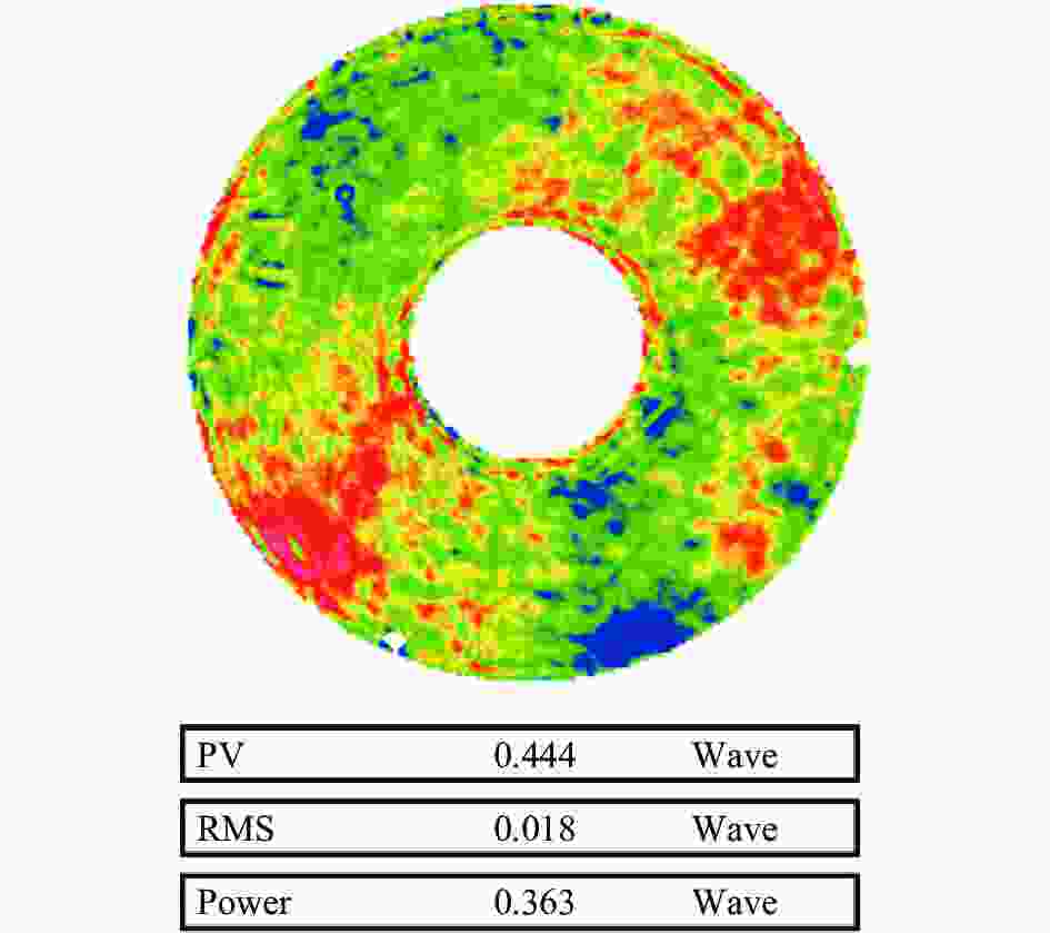
      Figure 15.  Measurement result of surface shape of mirror assembly

    • 为实现大口径反射镜Bipod支撑结构的高精度装配与调试,文中首先通过对遥感相机光学系统的误差指标进行分解,确定反射镜的装调指标要求。而后使用激光跟踪仪测量并构建反射镜与支撑垫的空间坐标系,采用基于标称点的坐标系恢复原理,实现坐标系的归一化,根据支撑垫上标称点的实测数据,完成支撑垫的位置矫正并固定。最后,基于Bipod结构自身特征,解算Bipod杆的长度与反射镜的位置关系,通过调节调节杆长实现反射镜与相机主体结构之间的位置调整。该装调方法已在北京三号B相机主反射镜的装调过程中进行应用验证,结果表明该方法可有效提升Bipod支撑结构反射镜的装调精度,减少因装调误差导致的反射镜面形与位置偏差。

Reference (13)

Catalog

    /

    DownLoad:  Full-Size Img  PowerPoint
    Return
    Return