Volume 53 Issue 4
Apr.  2024
Turn off MathJax
Article Contents

She Kai, Xie Pengjian, Zhou Pengfei, Wei Yong, Xu Shan, Li Bingxuan, Zhang Ge. Polarization manipulation in a quasi-continuous c-cut Er,Yb:YAl3 (BO3)4 laser[J]. Infrared and Laser Engineering, 2024, 53(4): 20230693. doi: 10.3788/IRLA20230693
Citation: She Kai, Xie Pengjian, Zhou Pengfei, Wei Yong, Xu Shan, Li Bingxuan, Zhang Ge. Polarization manipulation in a quasi-continuous c-cut Er,Yb:YAl3 (BO3)4 laser[J]. Infrared and Laser Engineering, 2024, 53(4): 20230693. doi: 10.3788/IRLA20230693

Polarization manipulation in a quasi-continuous c-cut Er,Yb:YAl3 (BO3)4 laser

doi: 10.3788/IRLA20230693
Funds:  Youth Innovation Promotion Association CAS (2022303); CAS Key Technology Talent Program (2022000061);National Natural Science Foundation of China (U21A20508, 61975208, 62105334); The Scientific Instrument Developing Project of the Chinese Academy of Sciences (YZLY202001); Fujian Science & Technology Innovation Laboratory for Optoelectronic Information of China (2021ZR203, 2020ZZ108, 2021ZZ118); Education Department of Hunan Province (22A0476); The Project of Science and Technology of Fujian Province (2021H0047)
  • Received Date: 2023-12-13
  • Rev Recd Date: 2024-01-31
  • Publish Date: 2024-04-25
  •   Objective  By constructing a resonant cavity model, the theoretical calculations reveal the spot singularity feature after coherent superposition of two intrinsic modes in an isotropic solid-state laser. And it is experimentally verified for the first time that the polarization state of the 1.6 μm output laser can be effectively manipulated in diode-pumped quasi-continuous c-cut Er,Yb: YAl3(BO3)4 lasers without using any specific intracavity optical polarization selector element. The transformation from a partially polarized state to a stable line-polarized state with a switchable orthogonal special case of line polarization direction is achieved, all with a polarization extinction ratio of 21 dB. It is also verified that the line-polarized output of the laser originates from the coherent superposition of two orthogonal eigenmodes by spot comparison. This thesis provides a reliable scheme for the direct output of line-polarized light from c-cut Er,Yb: YAl3(BO3)4 lasers with the modulation of polarization states.  Methods  The resonant cavity model is shown (Fig.1), where θ is denoted as the angle between the coordinate systems of the intracavity loss anisotropy ∆φ and the phase anisotropy ∆t. The experimental principle diagram of the c-cut Er,Yb: YAl3(BO3)4 polarization controlled laser is shown (Fig.3). The laser cavity has a length of approximately 32 mm, and the laser crystal is mounted on a water-cooled copper heat sink at 288.1 K. The output laser beam is split into two paths using a beam splitter (Splitter). In one of these paths, a Glan-Laser prism is employed as a polarizer, and a laser power meter (Thorlabs, Inc.) is used to measure the laser power after passing through the polarizer. Both measurements are utilized to determine the polarization state of the laser output. The other output laser uses an infrared camera and a spectrometer to detect the beam quality and emission wavelength of the output laser with different polarization states. In the experiment, by re-aligning the resonator, the output coupling mirror is slightly tilted, and the polarization state of the output laser is transformed from unbiased to linear polarization state, and the maximum polarization extinction ratio of linear polarization output is up to 21 dB.  Results and Discussions  By re-aligning the resonator, the output coupling mirror is slightly inclined, and the output laser polarization state is linearly polarized, and the polarization direction can be a set of orthogonal directions, and the polarization extinction ratio can reach 21 dB (Fig.4). Measurement of output laser wavelengths in different polarization states is carried out by spectrometer. When the polarization state changes, the center wavelength of the output laser fluctuates around 1 602 nm, with a maximum variation of less than 1 nm (Fig.6). The laser spot is detected after passing through the analyzer. When the angle of the Glan-prism is 0°, the laser power through the Grand prism is minimum. And when it is rotated and shifted by 0°, the line polarized light passes through the Glan-prism and the spot shows an elliptical distribution. And when the offsets are equal but in opposite directions, the ellipsoid-like spots can be observed, whose long axes are orthogonal to each other. The essence is that two orthogonally polarized eigenmodes undergo coherent superposition to produce a linearly polarized light output (Fig.7). Measurement of the beam quality factor M2 of different polarization states of the output laser is carried out by beam quality analyzer. The beam quality factor M2 of the partially polarized laser output when the laser is running freely and the linearly polarized laser output in two different polarization directions is maintained at about 2.0, and there is no obvious difference in beam quality degradation when the laser output linearly polarized laser (Fig.8),  Conclusions  In this study, theoretical calculations are performed by constructing a resonant cavity model to simulate the singular features of the spot profile after coherent synthesis of the intrinsic mode. And it is experimentally verified for the first time that in a quasi-continuously pumped c-cut Er,Yb: YAl3 (BO3)4 laser operated at 1.6 μm, the polarization state of the output laser can be switched from a partially polarized state to a stable linearly polarized state by adjusting the degree of tilt of the output coupling mirror, and the polarization extinction ratio reaches 21 dB, with a pair of orthogonal linear polarization directions that can be switched. In the process of adjusting the angle of the output coupling mirror, the output band of the output light is not changed, and the loss of output power of the generated linearly polarized beam is around 7%, while the quality of the beam in different polarization states does not change significantly. By spot comparison, it is verified that the direct output of line-polarized light from the laser is achieved by coherent synthesis of two orthogonal eigenmodes. This method provides a reliable solution for the direct output and modulation of line polarization of c-cut Er,Yb: YAl3 (BO3)4 and other isotropic lasers.
  • [1] Cao J, Poumellec B, Brisset F A L, et al. Tunable angular-dependent second-harmonic generation in glass by controlling femtosecond laser polarization [J]. Journal of Optical Society of America, 2016, 33(4): 741. doi:  10.1364/JOSAB.33.000741
    [2] Zhang M, Chu Y, Zhao J, et al. Efficient generation of third harmonics in Yb-doped femtosecond fiber laser via spatial and temporal walk-off compensation [J]. Chinese Optics Letters, 2021, 19(3): 03140.
    [3] EL-Damak A R, Chang Jianhua, Sun Jian, et al. Dual-wavelength, linearly polarized all-fiber laser with high extinction ratio [J]. IEEE Photonics Journal, 2013, 5(4): 1501406.
    [4] Deng S, Liu W, Shen H. Laser polarization imaging method based on frequency-shifted optical feedback [J]. Optics & Laser Technology, 2023, 161: 109099.
    [5] Wang J, Tang K F, Li B X, et al. Nd: YAG linearly polarized laser based on polarization eigenmodes [J]. Chinese Optics Letters, 2023, 21(11): 111401. doi:  10.3788/COL202321.111401
    [6] Liu Y, Zhang S, Cong Z, et al. Single-longitudinal-mode laser at 1123 nm based on a twisted-mode cavity [J]. Crystals, 2021, 11(1): 58. doi:  10.3390/cryst11010058
    [7] Guo L, Yang Y, Xu H, et al. High power linearly polarized diode-side-pumped Nd: YAG laser based on an asymmetric flat–flat resonator with the variable working point [J]. Optics Communications, 2022, 520: 128453. doi:  10.1016/j.optcom.2022.128453
    [8] Zhang S, Tan Y, Zhang S. Effect of gain and loss anisotropy on polarization dynamics in Nd: YAG microchip lasers [J]. Jounal of Optics, 2015, 17(4): 045703.
    [9] Akagla H, Chapron N, Loas G, et al. Control of the bipolarization emission of an Yb: YAG laser by the orientation of the pump polarization [J]. Optics Letters, 2023, 48(3): 700. doi:  10.1364/OL.475453
    [10] Dong J, Shirakawa A, Ueda K. A crystalline-orientation self-selected linearly polarized Yb: Y3Al5O12 microchip laser [J]. Applied Physics Letters, 2008, 93(10): 101105. doi:  10.1063/1.2980423
    [11] Dong J, Ma J, Ren Y Y. Polarization manipulated solid-state lasers with crystalline-orientations [J]. Laser Physics, 2011, 21(12): 2053-2058. doi:  10.1134/S1054660X11210043
    [12] Li Y Y, Chen W D, Lin H F, et al. Manipulation of linearly polarized states in a diode-pumped YAG/Tm: YAG/YAG bulk laser [J]. Optics Letters, 2014, 39(7): 1945. doi:  10.1364/OL.39.001945
    [13] Tang K F, Liao W B, Li K, et al. Coherent combination of two intracavity eigenmodes producing linearly polarized emission in an isotropic laser [J]. Optics Express, 2020, 28(23): 34337. doi:  10.1364/OE.405813
    [14] Huang Y C, Li B X, Zhang G, et al. Linear polarization emission of Yb: YAG laser via polarization mode frequency locking [J]. Infrared Physics & Technology, 2023, 128: 104516.
    [15] Laporta P, Taccheo S, Longhi S, et al. Erbium–ytterbium microlasers: Optical properties and lasing characteristics [J]. Optical Materials, 1999, 11(2-3): 269-288. doi:  10.1016/S0925-3467(98)00049-4
    [16] Sui J N, Wang Y L, Zhang Y, et al. Thermal effect analysis of LD end-pumped Er:Yb:glass/Co:MALO crysta [J]. Infrared and Laser Engineering, 2023, 52(8): 20230349. (in Chinese)
    [17] Chen Y J, Lin Y F, Huang Y D, et al. Enhanced performance of acousto-optic Q-switched Er: Yb: RAl3(BO3)4 (R = Y and Lu) pulse lasers at 1580 nm [J]. Laser Physics, 2013, 23(9): 095801. doi:  10.1088/1054-660X/23/9/095801
    [18] Młyńczak J, Kopczyński K, Mierczyk Z, M, et al. Comparison of cw laser generation in Er3+, Yb3+: glass microchip lasers with different types of glasses [J]. Opto-Electronics Review, 2011, 19(4): 3963-3968.
    [19] Guo N, Hui Y L, Cai J L, et al. LD pumped kHz Er3+, Yb3+: Glass passively Q-switched microchip lasers [J]. Infrared and Laser Engineering, 2018, 47(10): 1005002. (in Chinese)
    [20] Cheng Y, Zhang H, Zhang K, et al. Growth and spectroscopic characteristics of Er3+: YbVO4 crystal [J]. Journal of Crystal Growth, 2009, 311(15): 3963-3968. doi:  10.1016/j.jcrysgro.2009.06.033
    [21] Chen H Y, Dai J Z, Yang Y P, et al. Laser diode end-pumped Er-Yb co-doped phosphate glass waveguide amplifiers [J]. Chinese Journal of Lasers, 2004, 31(S1): 227. (in Chinese) doi:  10.3321/j.issn:0258-7025.2004.z1.078
    [22] Karlsson G, Laurell F, Tellefsen J, et al. Development and characterization of Yb-Er laser glass for high average power laser diode pumping [J]. Applied Physics B, 2002, 75(1): 41-46. doi:  10.1007/s00340-002-0950-4
    [23] Cheng W W, Zhang T S, Jiang Z Q, et al. 4.55 W continue-wave dual-end pumping of Er: Yb: YAl3(BO3)4 microchip laser at 1.5 μm [J]. Applied Physics Letters, 2023, 123(17): 171101. doi:  10.1063/5.0167529
    [24] Chen Y J, Lin Y F, Huang Y D, et al. Efficient continuous-wave and passively Q-switched pulse laser operations in a diffusion-bonded sapphire/Er: Yb: YAl3(BO3)4/sapphire composite crystal around 1.55 μm [J]. Optics Express, 2018, 26(1): 419. doi:  10.1364/OE.26.000419
    [25] Chen Y J, Lin Y F, Huang Y D, et al. Diode-pumped 1.5-1.6 μm laser operation in Er3+ doped YbAl3(BO3)4 microchip [J]. Optics Express, 2014, 22(11): 13969. doi:  10.1364/OE.22.013969
    [26] Chen Y J, Lin Y F, Huang J H, et al. Research progress in 1550 nm all solid state lasers based on Er3+ - doped crystals [J]. Chinese Journal of Lasers, 2020, 47(5): 0500018. (in Chinese)
    [27] Vallet M, Brunel M, Ropars G, et al. Theoretical and experimental study of eigenstate locking in polarization self-modulated lasers [J]. Physical Review A, 1997, 56(6): 5121-5130.
    [28] She K, Huang Y C, Li B X, et al. Rapid measurement method of intracavity phase retardation based on laser frequency splitting [J]. Optics Express, 2023, 31(21): 35032. doi:  10.1364/OE.502490
  • 加载中
通讯作者: 陈斌, bchen63@163.com
  • 1. 

    沈阳化工大学材料科学与工程学院 沈阳 110142

  1. 本站搜索
  2. 百度学术搜索
  3. 万方数据库搜索
  4. CNKI搜索

Figures(8)  / Tables(1)

Article Metrics

Article views(23) PDF downloads(8) Cited by()

Related
Proportional views

Polarization manipulation in a quasi-continuous c-cut Er,Yb:YAl3 (BO3)4 laser

doi: 10.3788/IRLA20230693
  • 1. College of Chemistry, Fuzhou University, Fuzhou 350108, China
  • 2. Key Laboratory of Optoelectronic Materials Chemistry and Physics, Fujian Institute of Research on the Structure of Matter, Chinese Academy of Sciences, Fuzhou 350002, China
  • 3. Fujian College, University of Chinese Academy of Sciences, Fuzhou 350002, China
  • 4. College of Chemistry and Materials Science, Fujian Normal University, Fuzhou 350117, China
  • 5. School of Physics and Electronic Science, Hunan Institute of Science and Technology, Yueyang 414006, China
  • 6. Hubei Key Laboratory of Low Dimensional Optoelectronic Material and Devices, Hubei University of Arts and Science, Xiangyang 441053, China
  • 7. Fujian Science & Technology Innovation Laboratory for Optoelectronic Information of China, Fuzhou 350108, China
Fund Project:  Youth Innovation Promotion Association CAS (2022303); CAS Key Technology Talent Program (2022000061);National Natural Science Foundation of China (U21A20508, 61975208, 62105334); The Scientific Instrument Developing Project of the Chinese Academy of Sciences (YZLY202001); Fujian Science & Technology Innovation Laboratory for Optoelectronic Information of China (2021ZR203, 2020ZZ108, 2021ZZ118); Education Department of Hunan Province (22A0476); The Project of Science and Technology of Fujian Province (2021H0047)

Abstract:   Objective  By constructing a resonant cavity model, the theoretical calculations reveal the spot singularity feature after coherent superposition of two intrinsic modes in an isotropic solid-state laser. And it is experimentally verified for the first time that the polarization state of the 1.6 μm output laser can be effectively manipulated in diode-pumped quasi-continuous c-cut Er,Yb: YAl3(BO3)4 lasers without using any specific intracavity optical polarization selector element. The transformation from a partially polarized state to a stable line-polarized state with a switchable orthogonal special case of line polarization direction is achieved, all with a polarization extinction ratio of 21 dB. It is also verified that the line-polarized output of the laser originates from the coherent superposition of two orthogonal eigenmodes by spot comparison. This thesis provides a reliable scheme for the direct output of line-polarized light from c-cut Er,Yb: YAl3(BO3)4 lasers with the modulation of polarization states.  Methods  The resonant cavity model is shown (Fig.1), where θ is denoted as the angle between the coordinate systems of the intracavity loss anisotropy ∆φ and the phase anisotropy ∆t. The experimental principle diagram of the c-cut Er,Yb: YAl3(BO3)4 polarization controlled laser is shown (Fig.3). The laser cavity has a length of approximately 32 mm, and the laser crystal is mounted on a water-cooled copper heat sink at 288.1 K. The output laser beam is split into two paths using a beam splitter (Splitter). In one of these paths, a Glan-Laser prism is employed as a polarizer, and a laser power meter (Thorlabs, Inc.) is used to measure the laser power after passing through the polarizer. Both measurements are utilized to determine the polarization state of the laser output. The other output laser uses an infrared camera and a spectrometer to detect the beam quality and emission wavelength of the output laser with different polarization states. In the experiment, by re-aligning the resonator, the output coupling mirror is slightly tilted, and the polarization state of the output laser is transformed from unbiased to linear polarization state, and the maximum polarization extinction ratio of linear polarization output is up to 21 dB.  Results and Discussions  By re-aligning the resonator, the output coupling mirror is slightly inclined, and the output laser polarization state is linearly polarized, and the polarization direction can be a set of orthogonal directions, and the polarization extinction ratio can reach 21 dB (Fig.4). Measurement of output laser wavelengths in different polarization states is carried out by spectrometer. When the polarization state changes, the center wavelength of the output laser fluctuates around 1 602 nm, with a maximum variation of less than 1 nm (Fig.6). The laser spot is detected after passing through the analyzer. When the angle of the Glan-prism is 0°, the laser power through the Grand prism is minimum. And when it is rotated and shifted by 0°, the line polarized light passes through the Glan-prism and the spot shows an elliptical distribution. And when the offsets are equal but in opposite directions, the ellipsoid-like spots can be observed, whose long axes are orthogonal to each other. The essence is that two orthogonally polarized eigenmodes undergo coherent superposition to produce a linearly polarized light output (Fig.7). Measurement of the beam quality factor M2 of different polarization states of the output laser is carried out by beam quality analyzer. The beam quality factor M2 of the partially polarized laser output when the laser is running freely and the linearly polarized laser output in two different polarization directions is maintained at about 2.0, and there is no obvious difference in beam quality degradation when the laser output linearly polarized laser (Fig.8),  Conclusions  In this study, theoretical calculations are performed by constructing a resonant cavity model to simulate the singular features of the spot profile after coherent synthesis of the intrinsic mode. And it is experimentally verified for the first time that in a quasi-continuously pumped c-cut Er,Yb: YAl3 (BO3)4 laser operated at 1.6 μm, the polarization state of the output laser can be switched from a partially polarized state to a stable linearly polarized state by adjusting the degree of tilt of the output coupling mirror, and the polarization extinction ratio reaches 21 dB, with a pair of orthogonal linear polarization directions that can be switched. In the process of adjusting the angle of the output coupling mirror, the output band of the output light is not changed, and the loss of output power of the generated linearly polarized beam is around 7%, while the quality of the beam in different polarization states does not change significantly. By spot comparison, it is verified that the direct output of line-polarized light from the laser is achieved by coherent synthesis of two orthogonal eigenmodes. This method provides a reliable solution for the direct output and modulation of line polarization of c-cut Er,Yb: YAl3 (BO3)4 and other isotropic lasers.

    • 偏振发射激光器已广泛应用于非线性频率转换[12]、激光干涉仪[3]、成像[4]等领域。一般来说,激光器使用具有光学各向异性的激光晶体作为增益介质会产生线偏振输出,使用具有光学各向同性的激光晶体则会产生非偏振光输出[5]。传统上想让使用具有光学各向同性晶体的激光器产生线偏振激光输出,常用的手段是使用偏振元件,例如腔内布鲁斯特板[67],偏振棱镜等。近年来有研究人员发现使用线偏振泵浦切换泵浦偏振态[89]、旋转晶体取向[1011]、调整输出耦合镜角度[1214]等方法同样可以获得线偏振激光输出。如果采用一个属于三方晶系或四方晶系的单轴晶体,沿c轴切割,其同样具有光学各向同性。但在先前的报道中,并没有此类晶体调整输出耦合镜的角度调控输出激光偏振态的相关研究。

      然而,在研究使用光学各向同性增益介质的偏振发射激光器时,1.5~1.6 μm人眼安全波段的重要性促使笔者去关注特定激光晶体的线偏振发射。其中属于三方晶系的Er, Yb: YAl3(BO3)4晶体备受研究人员的关注。对于能够产生1.5~1.6 μm这个波段的激光晶体中,相较于Er、Yb共掺的磷酸盐玻璃,Er, Yb: YAl3(BO3)4晶体从各种物理性能等方面表现得更为优异。如表1所示,Er、Yb共掺的磷酸盐玻璃具有较差的力学性能和导热系数(0.85 W·m−1·K−1),这使其会导致严重的热效应[1516],并限制了激光系统的入射泵浦功率和激光输出功率[1719]。而由于Yb3+离子的半径略小于Y3+离子, Er, Yb: YAl3(BO3)4晶体可以在不引起晶格畸变的情况下实现高浓度的Yb3+离子掺杂,从而提高激光晶体对泵浦光的吸收效率[20]。更重要的是,Er, Yb: YAl3(BO3)4晶体具有优异的导热系数(4.7 W·m−1·K−1)、较大的声子能量(1400 cm−1) [21]、Yb3+离子(2F5/2)到Er3+离子(4I11/2) 较高的能量传递效率(> 90%)、低的上转换以及可忽略的反向能量传递(4I11/22F5/2)[22]。而在以往的报道中,c切Er, Yb: YAl3(BO3)4由于其优越的光谱性能,成为相关研究人员的首选增益介质[2326]。因此,在对于偏振发射激光器的讨论中,有必要对c切Er, Yb: YAl3(BO3)4激光器腔内线偏振光的输出与调控作进一步研究。

      Thermal conductivity/
      W·m−1·K−1
      Emission cross section/
      cm−1
      Absorption cross section/
      cm−1
      Phonon energy/
      cm−1
      YAl3(BO3)4 4.70 1.7 3.0 1400
      Glass 0.85 0.8 1.0 1200

      Table 1.  Comparison of properties of Er, Yb: YAl3(BO3)4 and co-doped phosphate glass

      文中研究了c切Er, Yb: YAl3(BO3)4激光器直接线偏振光输出。通过构建谐振腔模型进行理论计算,模拟了在本征模式相干合成后的光斑轮廓奇异特征。并且实验验证了在不使用任何特定的腔内偏振元件的条件下,通过调整输出耦合镜,实现了准连续泵浦c切Er, Yb: YAl3(BO3)4激光器部分偏振光和线偏振光的输出与调控,其中包括可切换的正交线偏振光的输出,其偏振消光比均高达21 dB。并且结果显示,该方法损失输出激光的功率仅为7%左右。线偏振输出的光束轮廓特征表明激光器直接发射的线偏振光来源于两个正交偏振本征模式的相干叠加。这为c切Er, Yb: YAl3(BO3)4激光器线偏振的直接输出与偏振态的调控提供了可靠的方案。

    • 在各向同性的激光晶体中,由于晶体本身掺杂离子分布不均或者晶体生长过程中的残余内应力等因素,可能会使各向同性的激光晶体表现出弱的双折射特性,从而导致激光器发生频率分裂现象,即两个正交偏振本征模式存在一定频率差。在先前的报道中[27],有研究人员提出,通过微调谐振腔的两个参数——损耗各向异性(Δt)和相位各向异性(Δφ),即对应腔镜微调程度和晶体弱双折射大小,可以使得两个本征模式存在一个简并区,而在这个简并区中,两个本征模式的频率差将被调整为0。这为两个本征模式相干合成从而产生新的线偏振光这一可能性提供了依据。

      为了进一步验证,笔者对所使用的法布里珀罗谐振腔构建一个物理模型。基于损耗各向异性Δt和相位各向异性Δφ建立偏振本征模式在谐振腔内往返一周的琼斯矩阵(Round-trip Jones Matrix)数学模型,如图1所示。

      Figure 1.  Resonator model

      从晶体前端面开始,建立一个琼斯矩阵M,该矩阵表述见公式(1)。其中θ表示为腔内损耗各向异性Δφ和相位各向异性Δt两者坐标系之间的夹角。根据公式(2)和公式(3)可以解得M矩阵的特征值$ {\gamma }_{\mathrm{1,2}} $和特征向量$ {E}_{\mathrm{1,2}} $,其物理意义则为谐振腔内两个本征模式的光矢量和相位信息[28]。所以通过M的特征值和特征向量可以进行本征模式相干合成的光斑解析。当笔者给两个本征向量赋予一个类高斯的强度分布项${{\rm{e}}}^{G\left[x,y,{\sigma }_{x},{\sigma }_{y}\right]}$用于表征腔内两个本征模式。通过对类高斯分布项上的空间位置参数(x1, y1)、(x2, y2)和相应光斑的椭圆度参数$\left(\sigma_{x_1}, \sigma_{y_1}\right) $、$ \left(\sigma_{x_2}, \sigma_{y_2}\right)$进行控制,可以调节两个本征模式。然后对其进行矢量相加,用于表述两个模式的叠加,得到叠加后的光矢量V,如公式(4)所示。

      最后对合成的光矢量 V 添加一个检偏器 P,用于对光斑进行偏振态的检测,从而得到检偏后的光矢量${{V}}^{{'}} $,如公式 (5) 所示,由此可以模拟出两个正交本征模式相干合成后,随着检偏器角度 α 的改变,其光斑发生的对应变化。

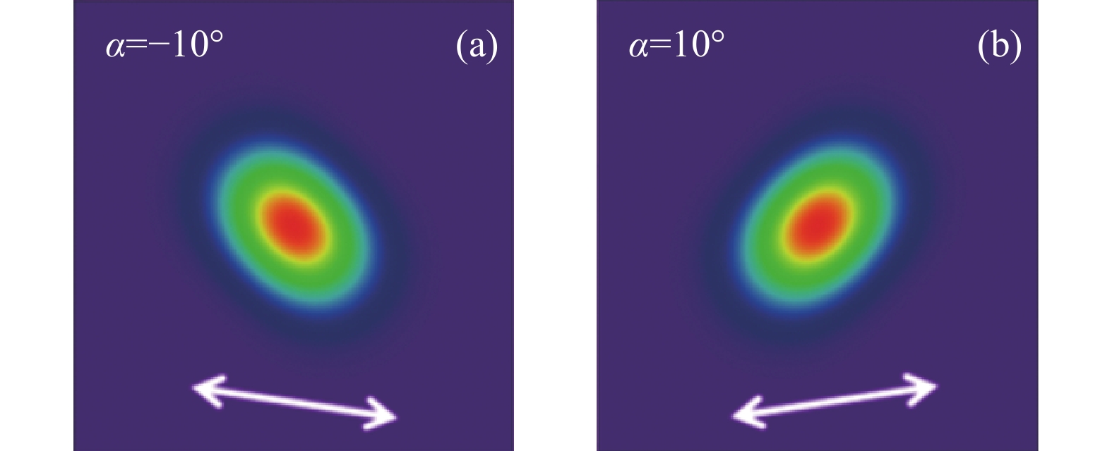
      当检偏器角度与线偏振光偏振方向相互垂直时,该偏振光几乎没有分量通过检偏器,定义此时检偏器角度为0°。即当检偏器的角度为0°时,通过检偏器的激光功率最小。改变检偏器角度,使其偏离功率最小位置±10°。输出线偏振态激光光斑的具体变化如图2所示。

      Figure 2.  Theoretical simulation results. (a) Simulated light spot when the polarizer angle is −10°; (b) Simulated light spot when the polarizer angle is 10° (Define the minimum power Glan-prism angle as 0°)

      可以看出,在功率最低位置的10˚处和−10˚处出现两个椭圆光斑,并且这两个光斑的长轴相互正交。为进一步探究输出耦合镜被倾斜不同程度对本征模式相干合成后的偏振光斑是否有影响,改变琼斯矩阵模型中的∆t用以表达不同程度的输出耦合镜倾斜量。重新探究不同检偏器角度的偏振光斑特性后,发现在检偏器角度为±10°时,偏振光斑并未出现明显改变,均呈现为两个椭圆光斑,并且这两个光斑的长轴相互正交。所以当两个本征模式相干合成后,两个长轴正交的椭圆光斑并不会随着输出耦合镜的微调发生改变或消失。这为各向同性晶体做增益介质的激光器直接输出线偏振光以及检验此线偏振光的产生原理均提供了相关理论依据。

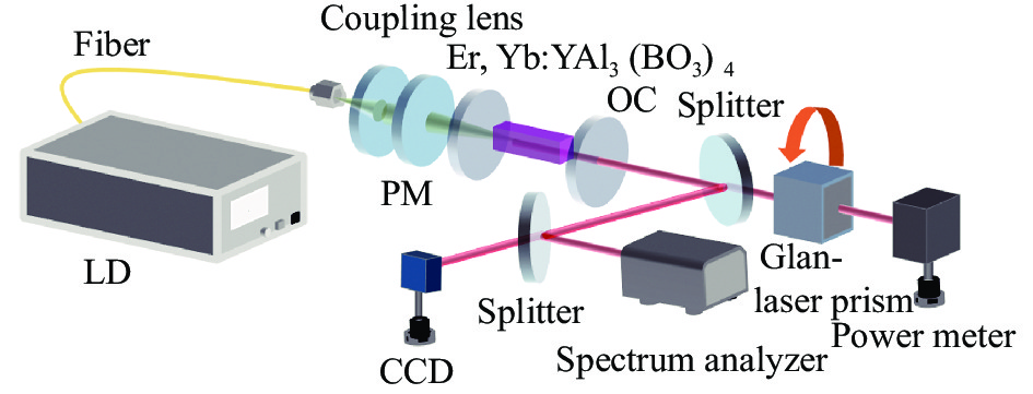
    • 文中的实验装置如图3所示,使用了一个c切Er, Yb: YAl3(BO3)4晶体作为激光增益介质,其中Er3+离子掺杂浓度为1.5 at.%, 作为敏化离子的Yb3+其掺杂浓度为12 at.%,晶体的尺寸大小为3 mm×3 mm×3 mm。采用的泵浦源为发射非偏振光的光纤耦合激光二极管(BWT Beijing Ltd),其输出功率最高为40 W,中心波长为940 nm,芯径为100 μm,数值孔径(NA)为0.22。通过一组耦合比为1∶1的准直系统将泵浦光准直后入射到增益介质的前端面。文中使用法布里泊罗腔作为激光的谐振腔,由一个平面泵浦镜和一个平面输出镜构成。其中,平面泵浦镜(PM)镀有对940 nm高透(T>97%@940 nm)以及对1 500~1 600 nm的高反的膜(R>99.8%@1 500~1 600 nm,平面输出耦合镜(Output Coupler, OC)在1 500~1 600 nm波段处镀有透过率为6%的部分反射膜。激光器的腔长约为32 mm,激光晶体被铟箔包裹,安装在286.5 K的水冷铜块上进行散热。输出激光通过一个分光镜(Splitter),将光路分成两路。在其中一路上,利用一个格兰棱镜(Glan-Laser Prism) 作为检偏器,使用激光功率计(Thorlabs, Inc, PM100D)测量通过检偏器后的激光功率,实现输出激光的偏振状态检测,其中格兰棱镜的透射波长范围为350~2300 nm。另一路的激光使用光束质量分析仪(DataRay, Inc, S-WCD-LCM-C-TEL)和激光光谱分析仪(Bristol Instruments, Inc, 821)探测不同偏振态输出激光相应的光束质量、光斑椭圆度以及激光发射波长。

      Figure 3.  Experimental device diagram

    • 文中输出激光的线偏振程度通过偏振消光比(PER)来量化。如公式(6)所示,偏振消光比定义为两个正交偏振方向上的光功率比,单位为dB。

      图4(a)所示,当谐振腔进行校准后,激光器拥有最大输出功率时(在自由运行状态下),通过使用格兰激光棱镜记录不同角度的激光输出功率(将水平方向定义为0°,垂直方向为90°),可以看出输出光束没有表现出明显的偏振特性,其PER仅有2 dB,为部分偏振光。定义光束传播方向为z轴,与光束传播方向相垂直的平面为x-y平面。当重新对准输出耦合镜的角度,使得输出耦合镜与x-y平面呈现极小倾角,可以使激光器获得稳定的线偏振态输出。如图4(b)所示,实现了两个不同方向的线偏振光。通过格兰棱镜作为检偏器,验证了这两个线偏振光的偏振方向分别为40°和130°,相互正交,且其PER均为21 dB。

      Figure 4.  Normalized transmission power as a function of polarizer angle for (a) free running operation and (b) linear polarization operation

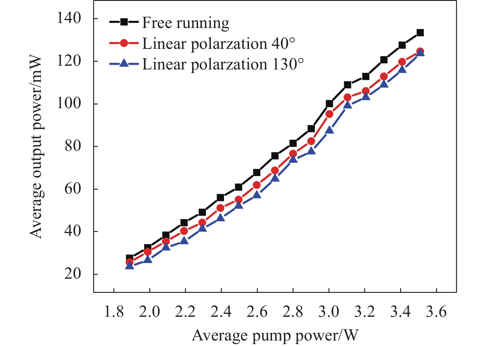
      图5显示了当输出耦合镜的透过率为6%时,去掉格兰棱镜后,法布里珀罗谐振腔中自由运转和线偏振操作的激光性能。在占空比为10%,重复频率为100 Hz的准连续泵浦的条件下,当泵浦的平均功率为1.9 W时激光器输出趋于稳定。通过使用准连续泵浦有效降低的激光器热效应,平均输出功率随着泵浦功率呈线性增加。从图5可以看出,激光器自由运转时输出的部分偏振激光在泵浦平均功率为3.5 W时,其功率为135 mW。而对于通过微调腔镜所产生的40°和130°线偏振激光,在同样的泵浦功率下,其输出功率分别为127 mW和125 mW。对于两种不同的线偏振状态,最大输出功率分别是自由运转状态下最佳功率的93.3%和92.5%,说明腔镜调节引入的损耗很小。

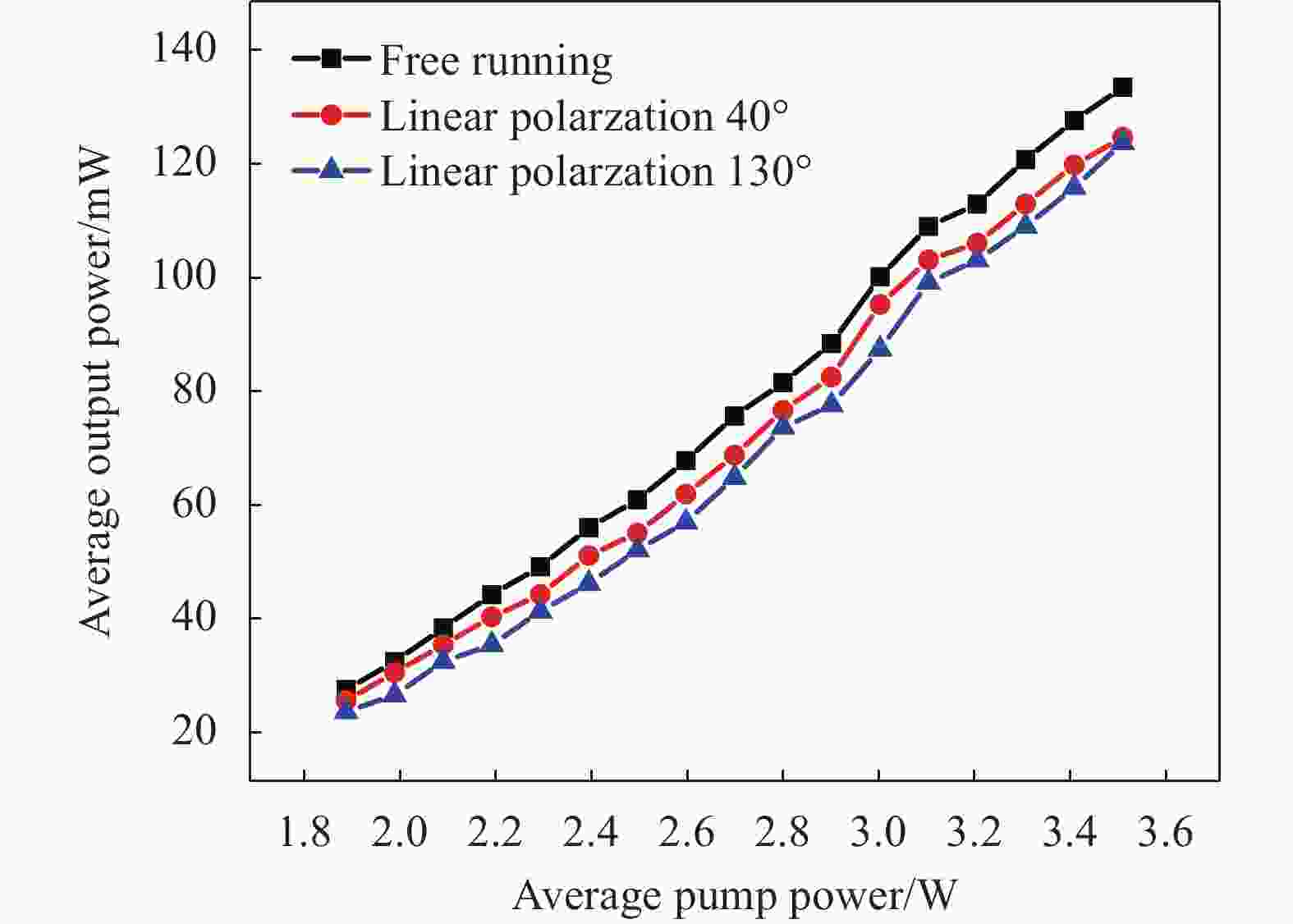
      Figure 5.  Relation between output power and pump power for free operation and linear polarization operation

      由于Er, Yb: YAl3 (BO3)4具有多个发射波段,并且输出耦合镜为宽带镀膜,其在1531 nm、1550 nm和1602 nm等波段处的透过率均非常接近。在输出耦合镜略微倾斜的过程中,不同波长的透过率略有变化。所以文中使用了一台激光光谱分析仪,对自由运转状态和线偏振状态的输出激光分别进行了发射光谱的测量。如图6所示,通过腔镜的微调使得输出激光的偏振态发生变化时,测得两种不同偏振态的中心波长分别为1601.8 nm和1602.4 nm,保持在1602 nm左右,其最大波动范围在1 nm以内。实验证明,不同偏振态下输出激光的中心波长变化很小。所以通过腔镜微调所引起的对不同波段透过率的变动不会导致输出激光波长发生改变。

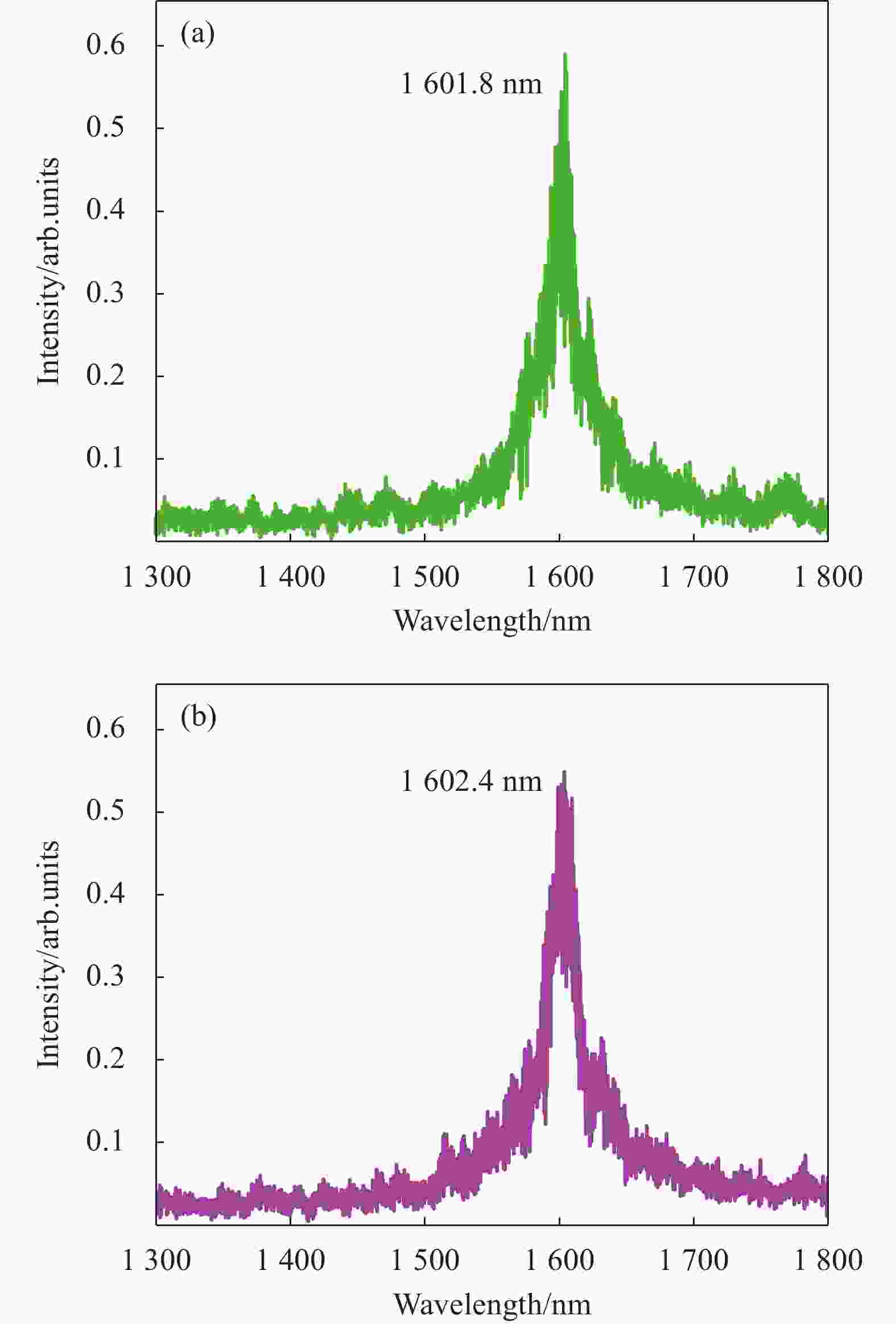
      Figure 6.  (a) Spectrum in free-running operation; (b) Spectrum of linearly polarized

      笔者使用Dataray的光束质量分析仪记录输出激光的光束轮廓。首先通过检偏器后对激光光斑进行检测。当格兰棱镜的角度为0°时,通过格兰棱镜的激光功率最小。而将其转动偏移±10°时,如图7所示,此时线偏振光通过格兰棱镜后光斑呈现椭圆状分布。并且当格兰棱镜偏移量相等但方向相反时,可以观察到类椭圆状的光斑,并且其长轴相互正交。同时在激光器达到阈值条件下,持续微调输出耦合镜的倾斜,当格兰棱镜偏移±10°时,其光斑保持为两个长轴正交的椭圆形状,这与理论模拟结果相吻合。所以在c切Er, Yb: YAl3(BO3)4激光器中,仅通过调节输出耦合镜的倾斜可以实现线偏振光的直接输出。其本质为两个正交的本征模式发生了相干叠加,从而产生线偏振光输出。

      Figure 7.  Laser spot at different angles of the Glan-prism. (a) Glan-prism angle is −10°; (b) Glan-prism angle is 10° (Define the minimum power Glan-prism angle as 0°)

      最后,在不使用检偏器的情况下,对不同偏振态的输出激光进行光束质量的检测。从图8(a)~(c)可以看出,在x轴和y轴两个方向上,激光器自由运转时输出的部分偏振激光和两个不同偏振方向的线偏振激光的光束质量因子M2均保持在2.00左右,未见明显差异且在激光器输出线偏振激光时,无光束质量退化。这表明激光器在部分偏振和线偏振两种偏振态分别输出时,其光束质量保持一致。并且在三种不同情况的激光光束光腰位置,分别测量其光斑椭圆度($ {E}_{p} $),定义椭圆度公式如下:

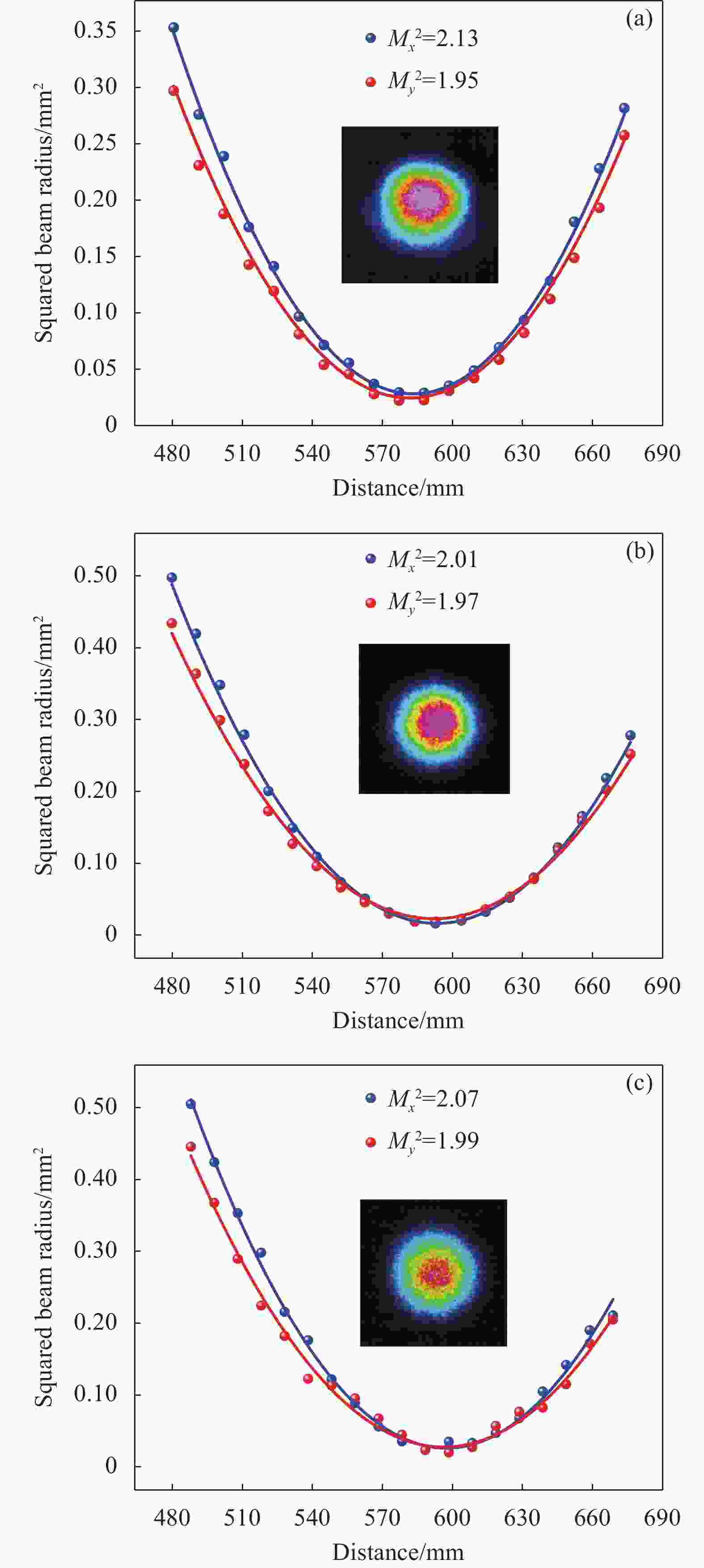
      Figure 8.  (a) Beam quality in free running operation; (b) Beam quality of 40° linear polarization; (c) Beam quality of 130° linear polarization

      式中:$ {d}_{s} $为椭圆的短轴长度;$ {d}_{l} $为椭圆的长轴长度。根据上述公式可得,激光器自由运转时光束的光斑椭圆度为0.08,而两个不同偏振方向的线偏振光束的光斑椭圆度均为0.04。由此可以看出,通过调整腔镜得到的线偏振光,其激光光束椭圆度更接近于0,光斑形状更接近于圆形。实验证明,通过腔镜微调所得到不同偏振态的输出激光,光束质量并未受到谐振腔的调整而有所损失。

    • 文中通过构建谐振腔模型进行理论计算,模拟了在本征模式相干合成后的光斑轮廓奇异特征。并且实验验证了在1.6 μm工作的准连续泵浦c切Er, Yb: YAl3(BO3)4激光器中,通过调整输出耦合镜的倾斜程度,可以将输出激光的偏振态由部分偏振态切换至稳定的线偏振态,偏振度消光比达到21 dB,可切换的线偏振方向为一对正交方向。在调整输出耦合镜角度过程中并不会改变输出光的波段,且产生线偏振光束输出功率的损失均在7%左右,同时不同偏振态的光束质量也未发生明显变化。通过光斑对比,验证了激光器线偏振光的直接输出是通过两个正交本征模式的相干合成实现的。该方法为c切Er, Yb:YAl3(BO3)4等同类型激光器线偏振的直接输出与调控提供了可靠的方案。

Reference (28)

Catalog

    /

    DownLoad:  Full-Size Img  PowerPoint
    Return
    Return